When launching Putty, you should have 'Session' tab selected on the left side, then under connection type, select Serial (the serial radio button) change the speed to 115200. Find the necessary COM, to do this, go to device manager to find it. I believe it's COM3. Click the Terminal tab and select Blinking Text. Click on Terminal->Keyboard (on Left) Select the VT100+ Radial button. Go back to the Session Tab and name the session and save it. you can use it later. When loading a session, you can load settings and then change as you please. So to get a logging, you need to load your saved settings. then go to 'Logging' under the 'Session' tab change the session logging to 'printable output' select the file to save the output to under log file name. Click 'Open' to launch the logged session.
Read Mastering STM32, Read 6.2.2 GPIO Alternate Function and 6.3 Driving a GPIO and deinitialize a GPIO.
Mastering STM32 by Carmine Noviello, Read 6.2 GPIOs Configuration section and the section 6.2.1 GPIO Mode.
From Mastering STM and consulting a colleague, acquired a usable working definition of a struct. Essentially it's a marshal of Data that's specifically categorized for certain uses.
Read Mastering STM32 by Carmine Noviello, Read from chapter 6 GPIO Management 6.1 STM32 Peripherals Mapping and HAL Handlers. Specifically read about the section of Exposure of bus architecture of an stm32F072 microcontroller.
From Mastering STM32 book by Carmine Noviello Read a formal introduction to STM32 Microcontrollers which topics include Advantes of the STM32 Portfolio and Drawbacks, STM32 subfamilies and their Hardware Details.
Read the Mastering STM32 book by Carmine Noviello. Briefly learned about concepts like Thumb-2 and Memory Alignment STM32 Pipeline, STM32 Interrupts and Exceptions Handling, SysTimer, Power Modes, and CMSIS.
From the Mastering STM32 book by Carmine Noviello, learned about the importance of bit banding. Which is using bit masking to save memory. Bit banding is mapping each bit of a "given area of memory" to a whole word in the aliased bit-banding memory regions.
From Mastering STM32 A step-by-step guide to the most complete ARM cortex-M platform by Carmine Noviello, read the overview of Cortex and Cortex-M Based Processors. And re familiarized myself with Cortex-M Registers and how assembly code moves information to the registers.
Wrote the Readme page on the MS project repository. This contains a short description of MM1 Minute Hand and the challenges faced when developing the project. The description of the MCU program is attached to the Readme as well.
Wrote the Readme page on the MS project repository. This contains a short description explaining the aim of 03003. Also the description of the MCU program for this project was also added to the Readme.
Contributed to the MP09 Wiki. Added a list of the commonly used footprints for reference.
Contributed to MP09 Wiki. Wrote and Posted the PCB Design Process page.
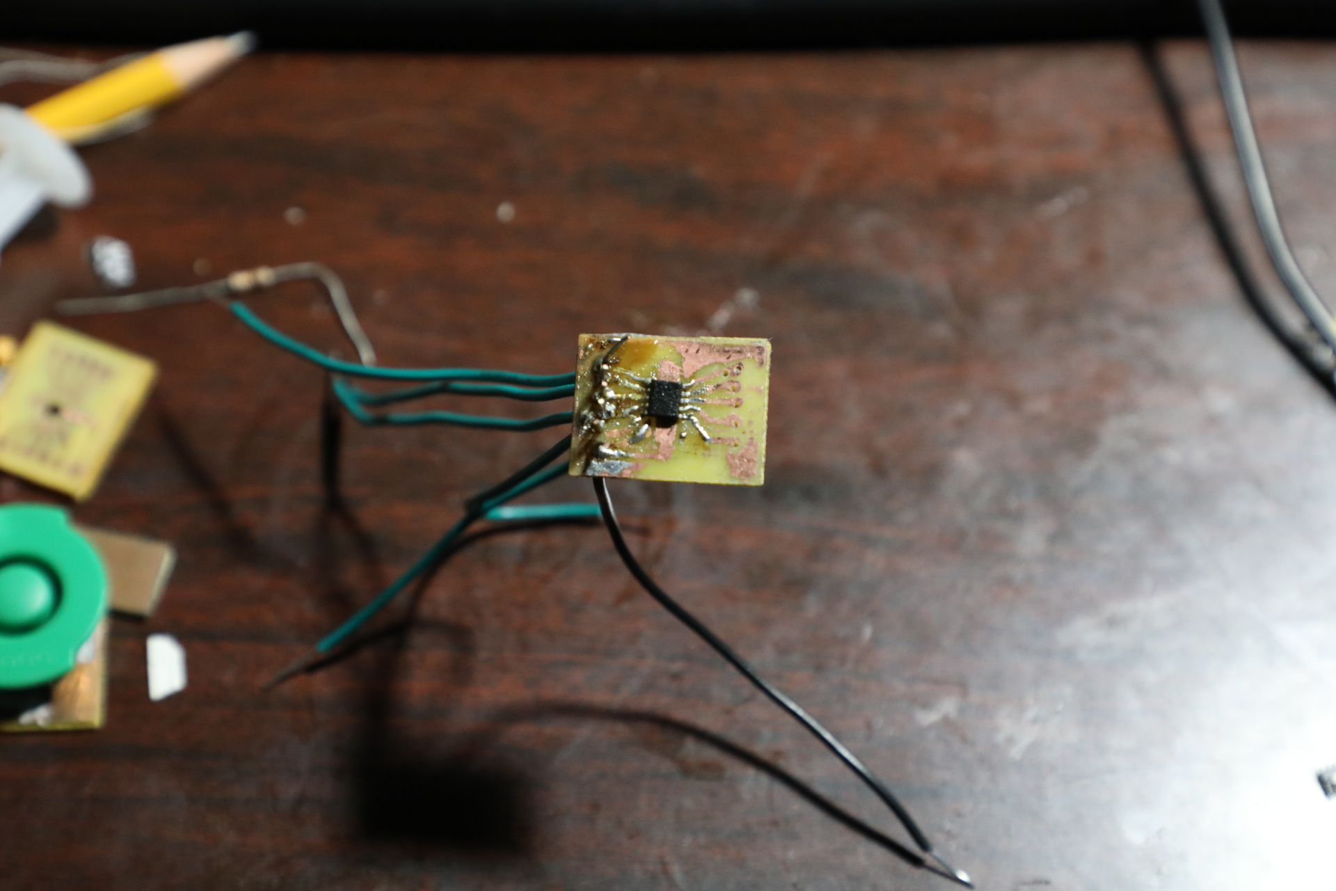
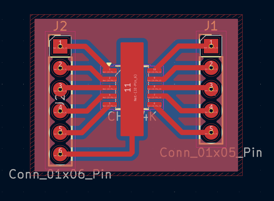
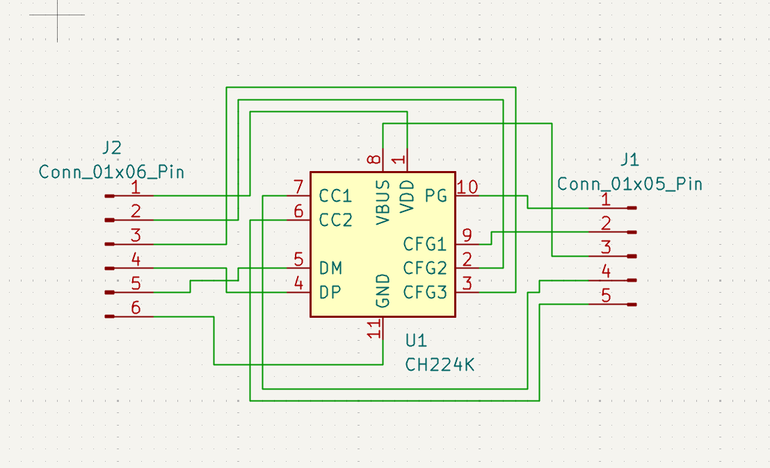
Manufactured the CH224K Breakout. It's mostly finished. The connections have been tested with a multimeter and are sound. The PCB was etched with ferric chloride and then drilled. The CH224K was then soldered to the Board.
The rightmost breadboard was replaced and all of the components were replaced into another breadboard. The encoder section of the circuit (leftmost breadboard) had 10k resistors removed and the signals from the encoder had more fidelity. The encoder signals were routed to the 74LS00 (which acts as an isolation to the MCU and an inversion) and the output of those are connected to the Atmega328P. The Code was then updated and we have a visible reading from the seven segment displays. But not everything is working. The Segment displays do not output a live reading from the enocder very well. 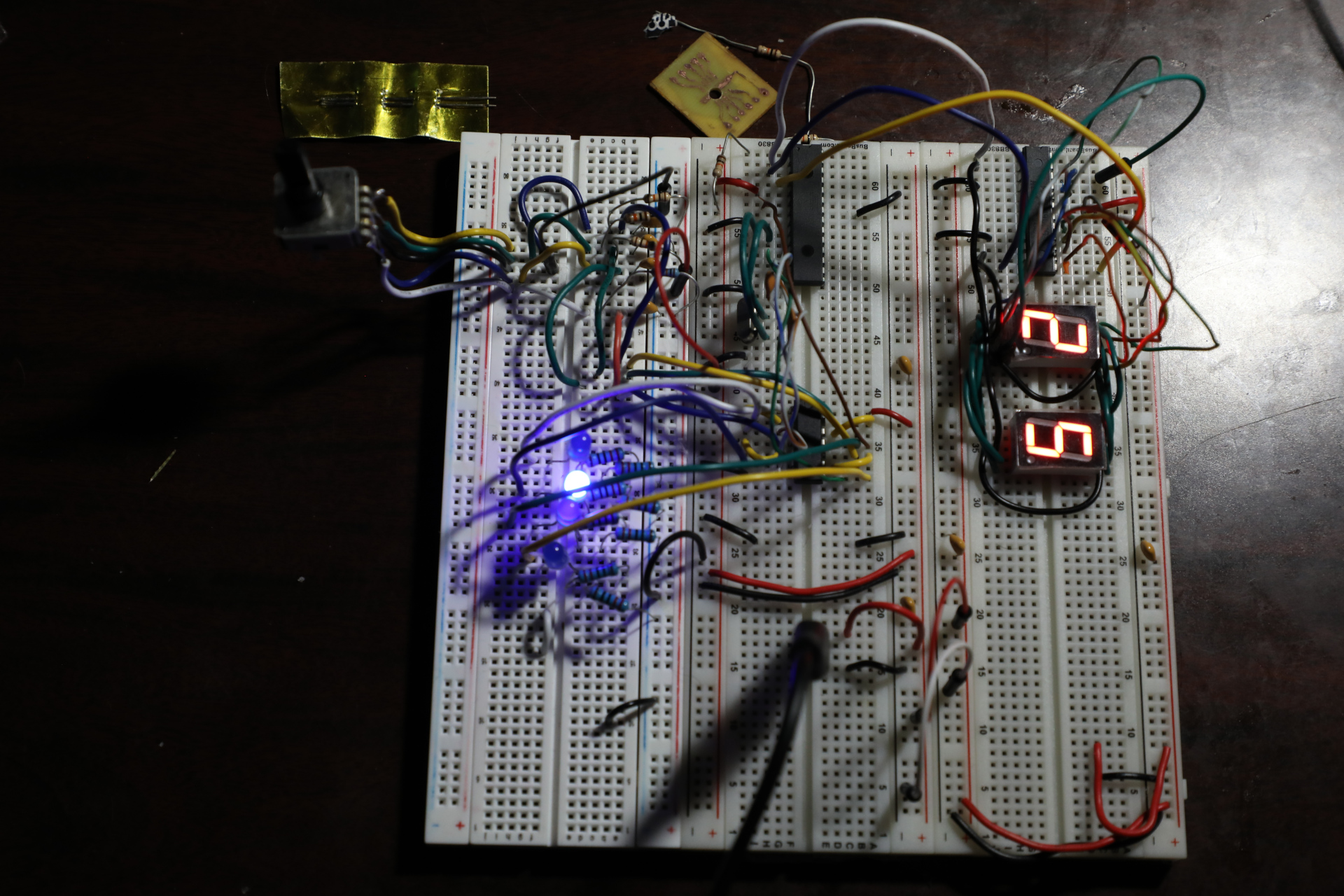
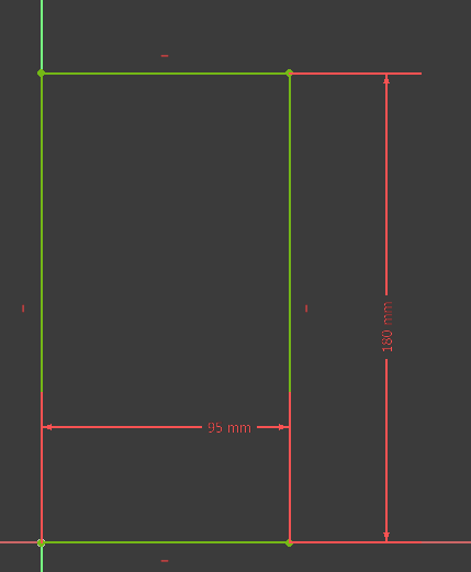
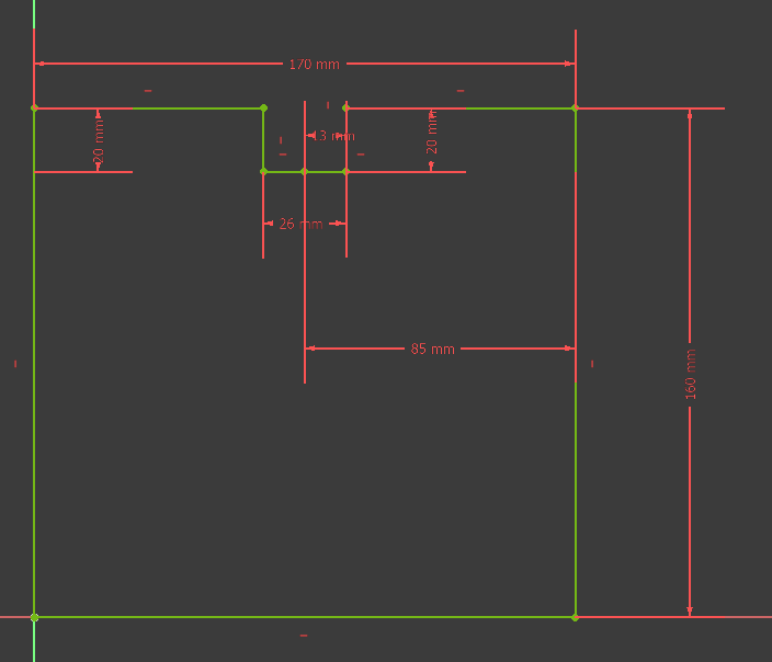
Designed a stackable case to contain various electronics for prototyping. The idea is that these small containers can be stacked on top of eachother on a desk, or shelf. 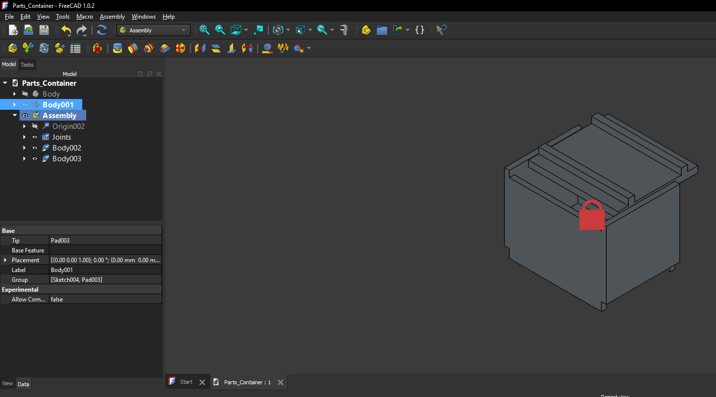
Designed a Resistor Holder for convenience when prototyping on a breadboard. It's easier than opening a plastic bag to get the resistors. 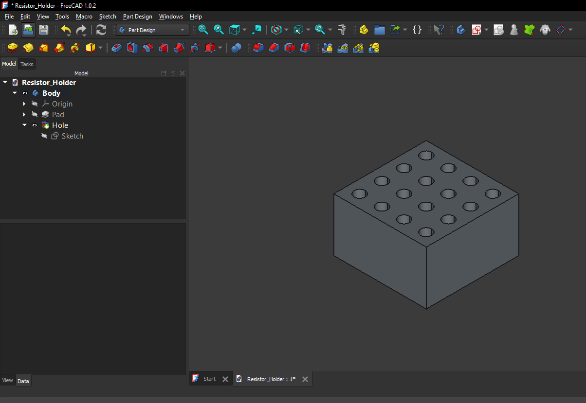
Took a AI generated Company quiz on the Max7219 Datasheet found here: https://www.analog.com/media/en/technical-documentation/data-sheets/max7219-max7221.pd
Read 62 pages of Computer Organization and Design 5th Edition by Patterson and Hennessy. And Read 38 pages of Microwave and RF Design Radio Systems volume I 3rd Edition by Michael Steer.
Made progress on the ch224k breakout pcb. 1 was successful and 2 failed. I believe the first succeeded because it was allowed to cool off before submerged in water. 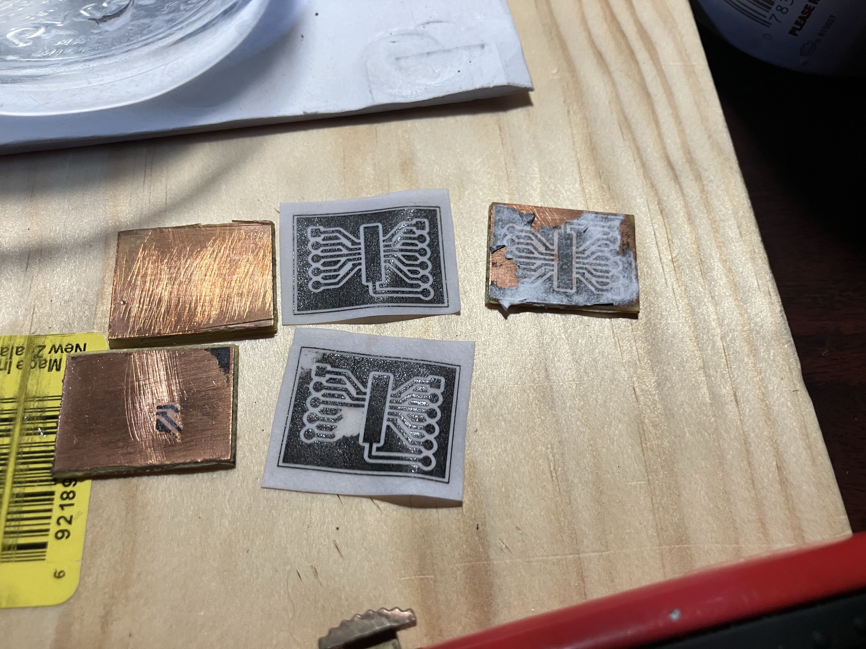
Designed breakout for ESSOP-10 IC. This is designated for testing purposes on a breadboard. 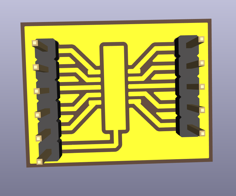
Today I updated the 02004-001 PCB.
Last week I made a parts List that's necessary for the manufacture of the 02004.
Yesterday, a PCB of the Firewire PD was designed. This design is designated for prototyping and isn't considered final. Surface mount components will be used for this project and thus the copper for this will be on the top (front) as opposed to earlier designs where the back was reserved for the copper. There is one rear copper connecter that will be implemented via a jumper.
The DIP Firewire (Keystone makes a version called 930) was ordered and the 4 pin Firewire was ordered. The DIP Firewire ordered from here and the footprint was modeled from here (the 930 from Keystone Electronics). There wasn't a footprint model provided from the retailer, so one was taken elsewhere. The 4 pin Firewire ordered from here had a footprint provided and my custom footprint was modeled from that.
A couple of days ago, I was tasked to create a PCB that essentially converts power from a USB-C to a firewire socket. A rough schematic was made and a custom footprint was created for the anticipated firewire female port. Yesterday, the Schematic was updated from a reference workflow doesn't have a footprint for the IEEE1394 (firewire) female port. So a suitable part was researched for this project and one was found on mouser here and Digikey as well, here . This is the 929 by Keystone Electronics. This datasheet schematic was used to make a custom footprint for the 929. Here's the custom footprint.
Yesterday, I burned a bootloader on the atmega328P chip, which is now removed from the board shown below. 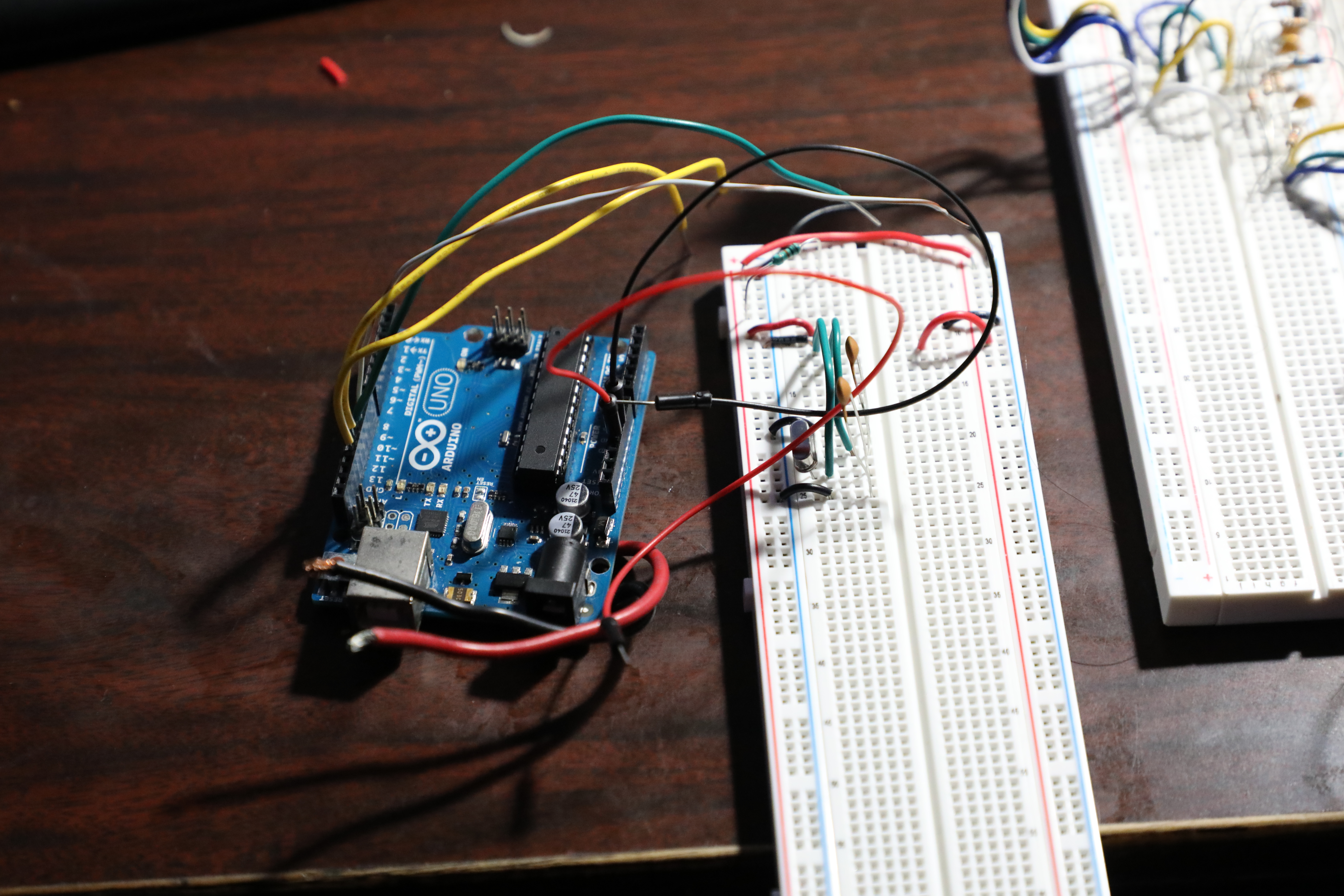
Yesterday, I programmed another stm32 bluepill and I added a Logic Leveler from 3.3V to 5V.
Yesterday, When the Mounted seven segment displays arrived, I realized I has a little problem. This is a front that was designed by myself for MM1 Minute hand.
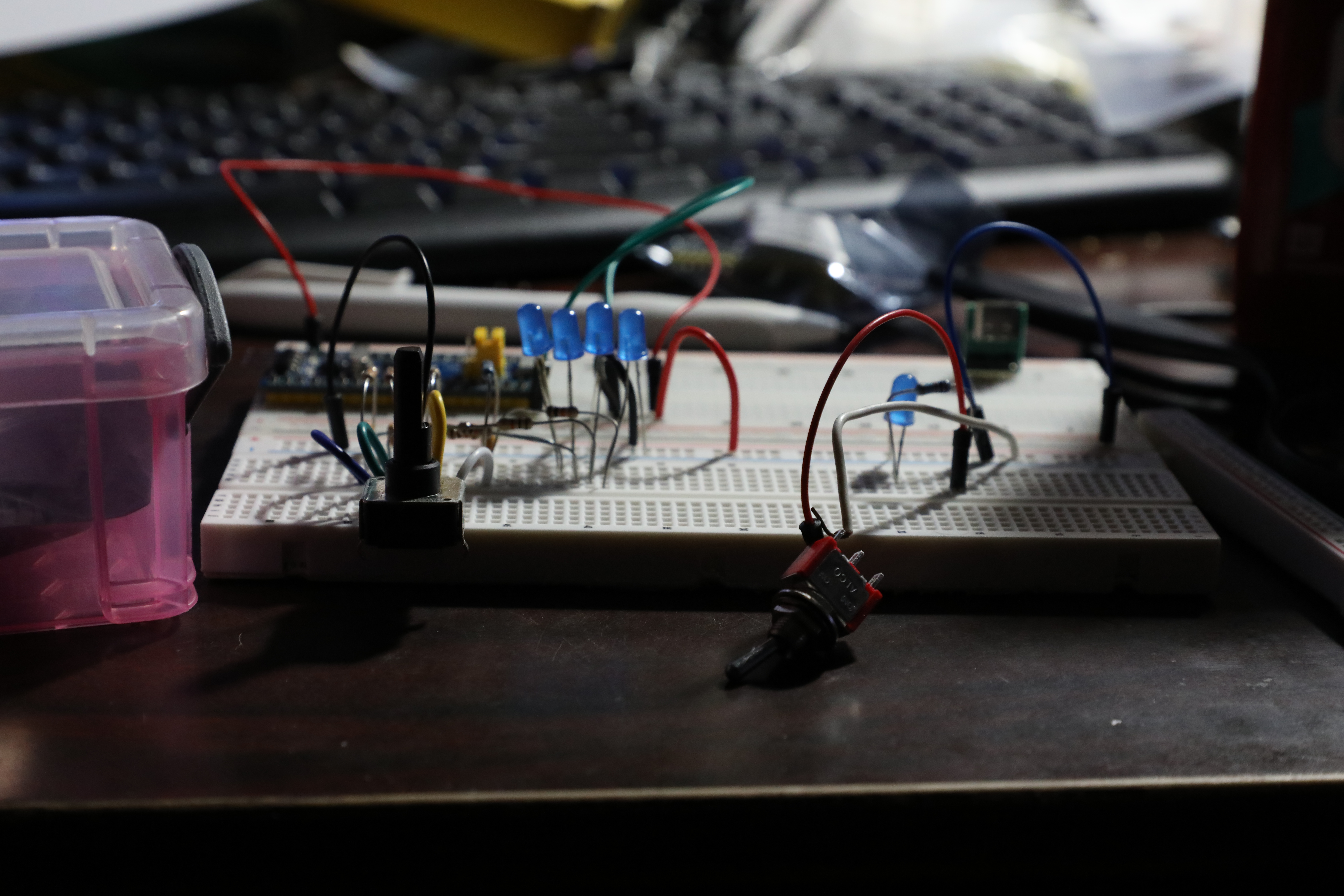
A few days ago, there was a lot of work done. The circuit was constructed on a breadboard. 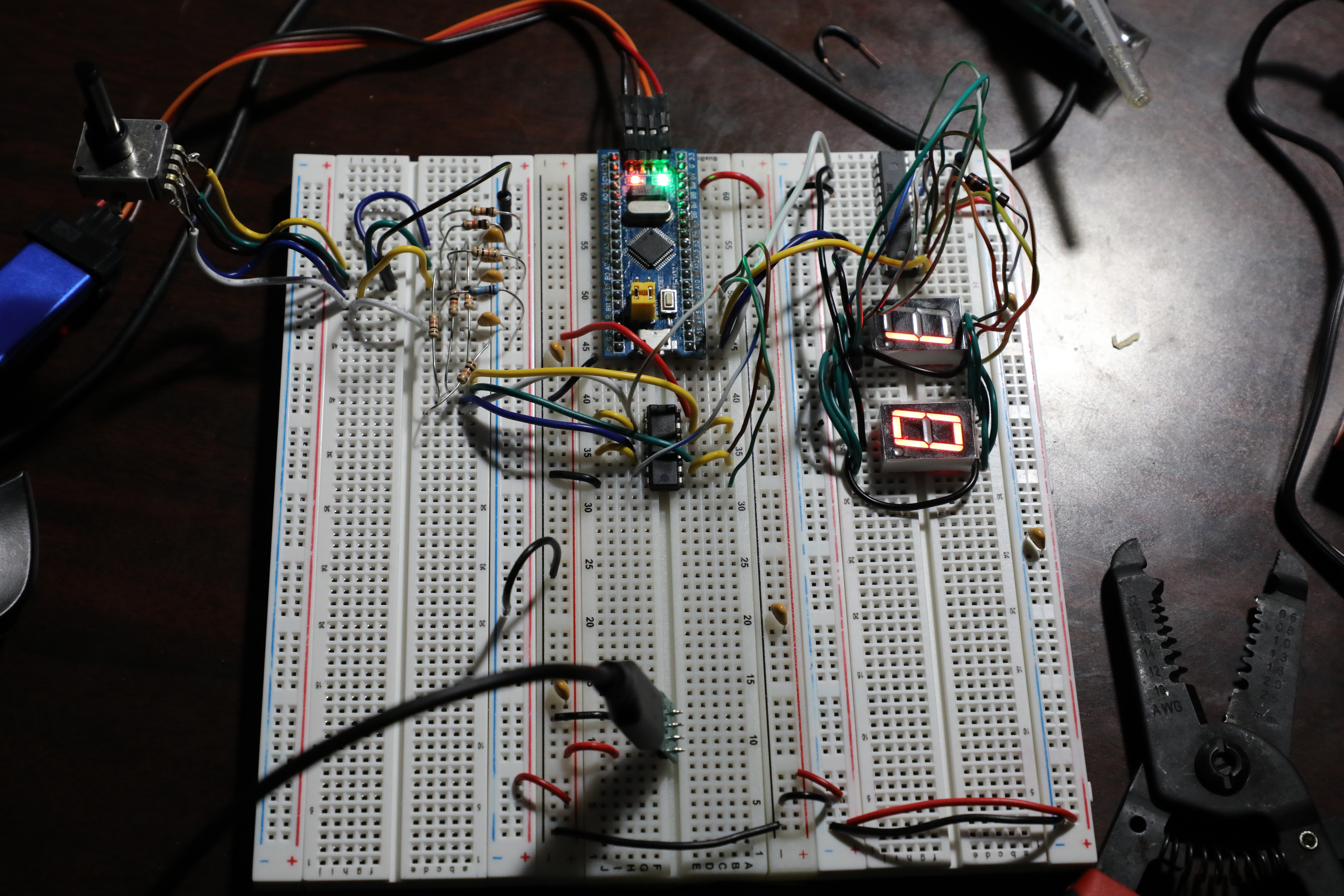
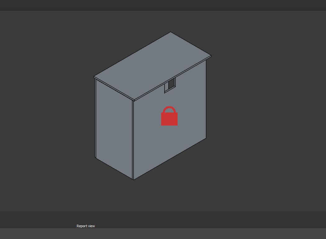
Here is an isometric view of 03009 MM1 Minute Hand with a 'cutoff' from the front panel.
Over the past several days, there was a major effort to complete the CAD for the MM1 Minute hand gears.
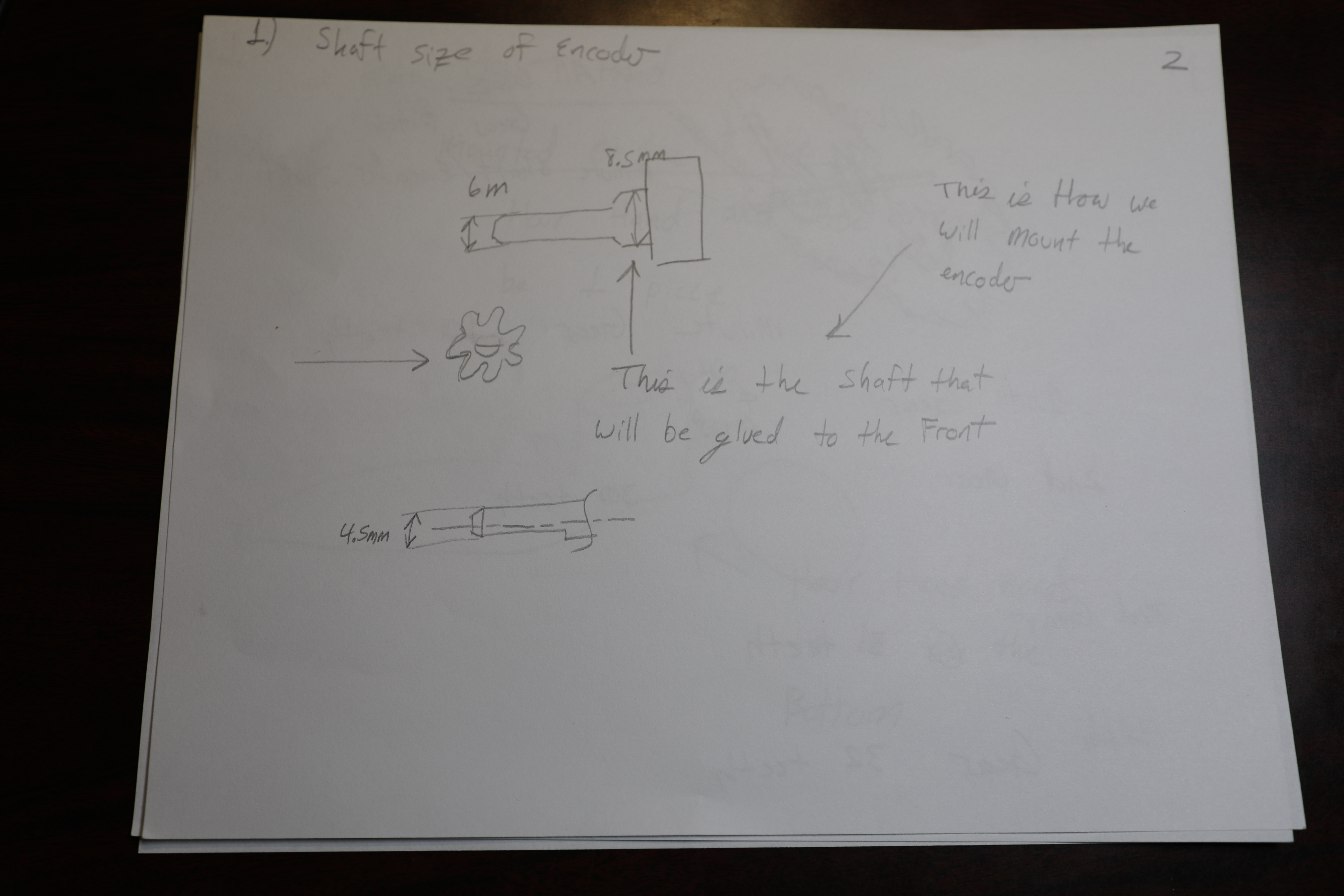
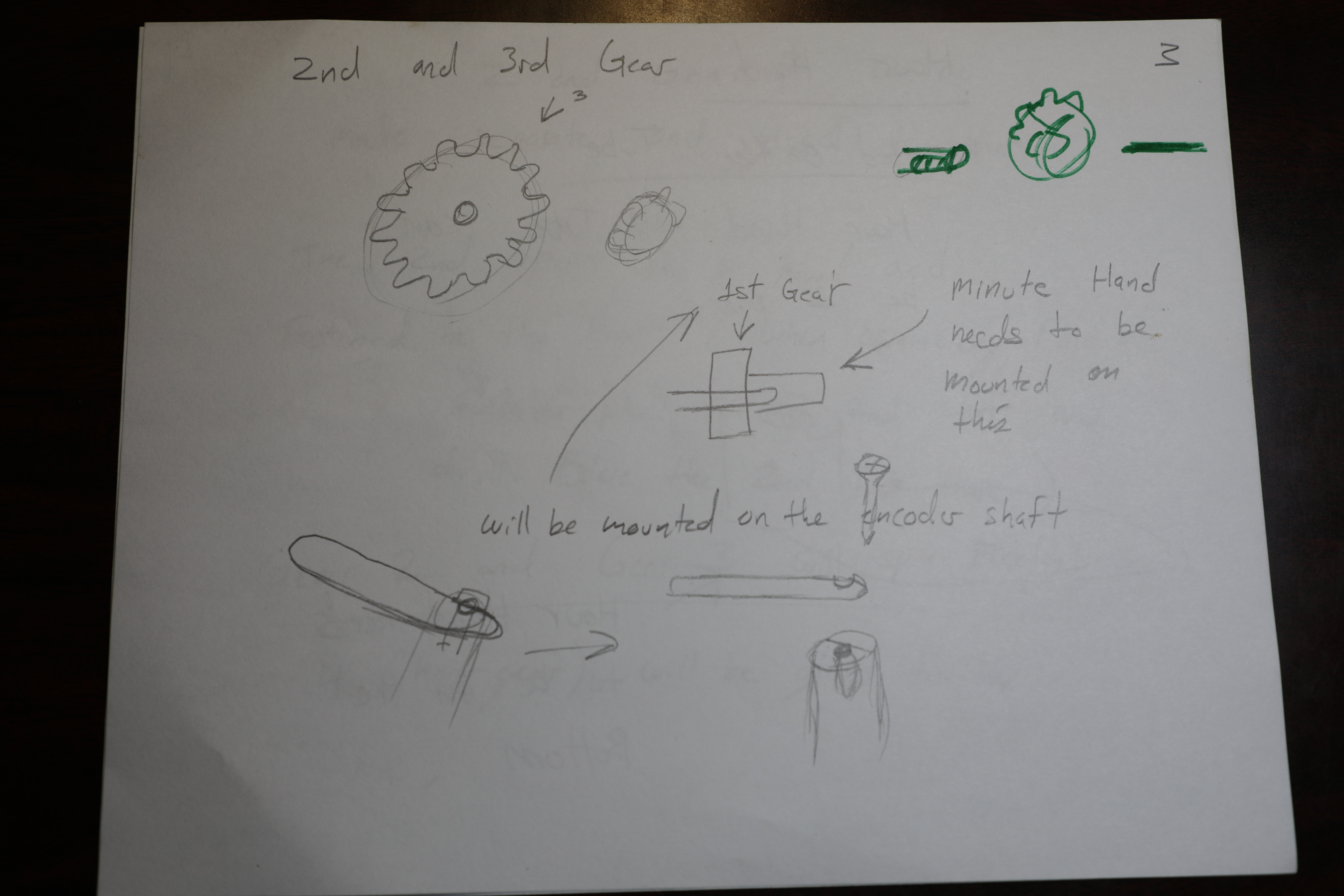
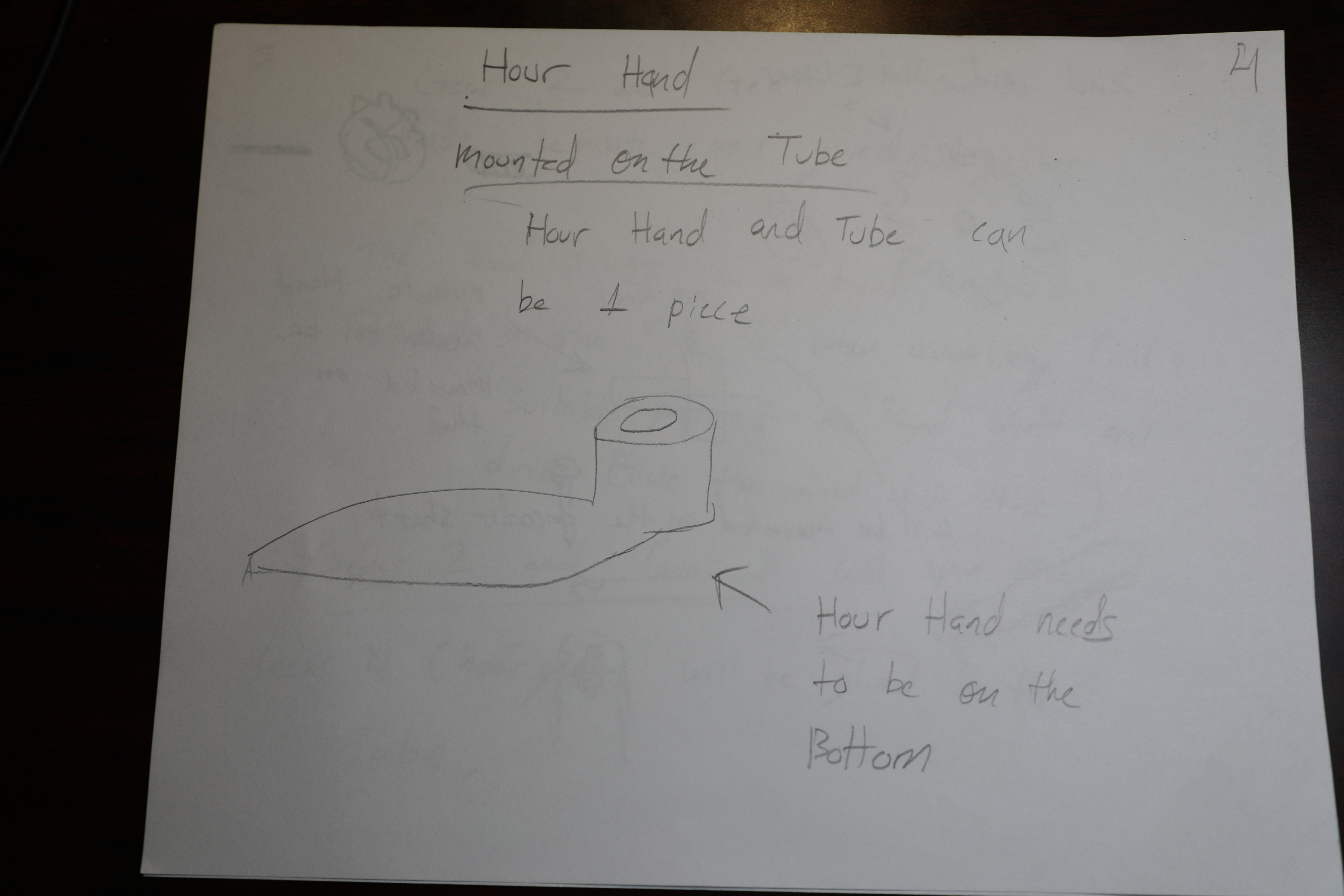
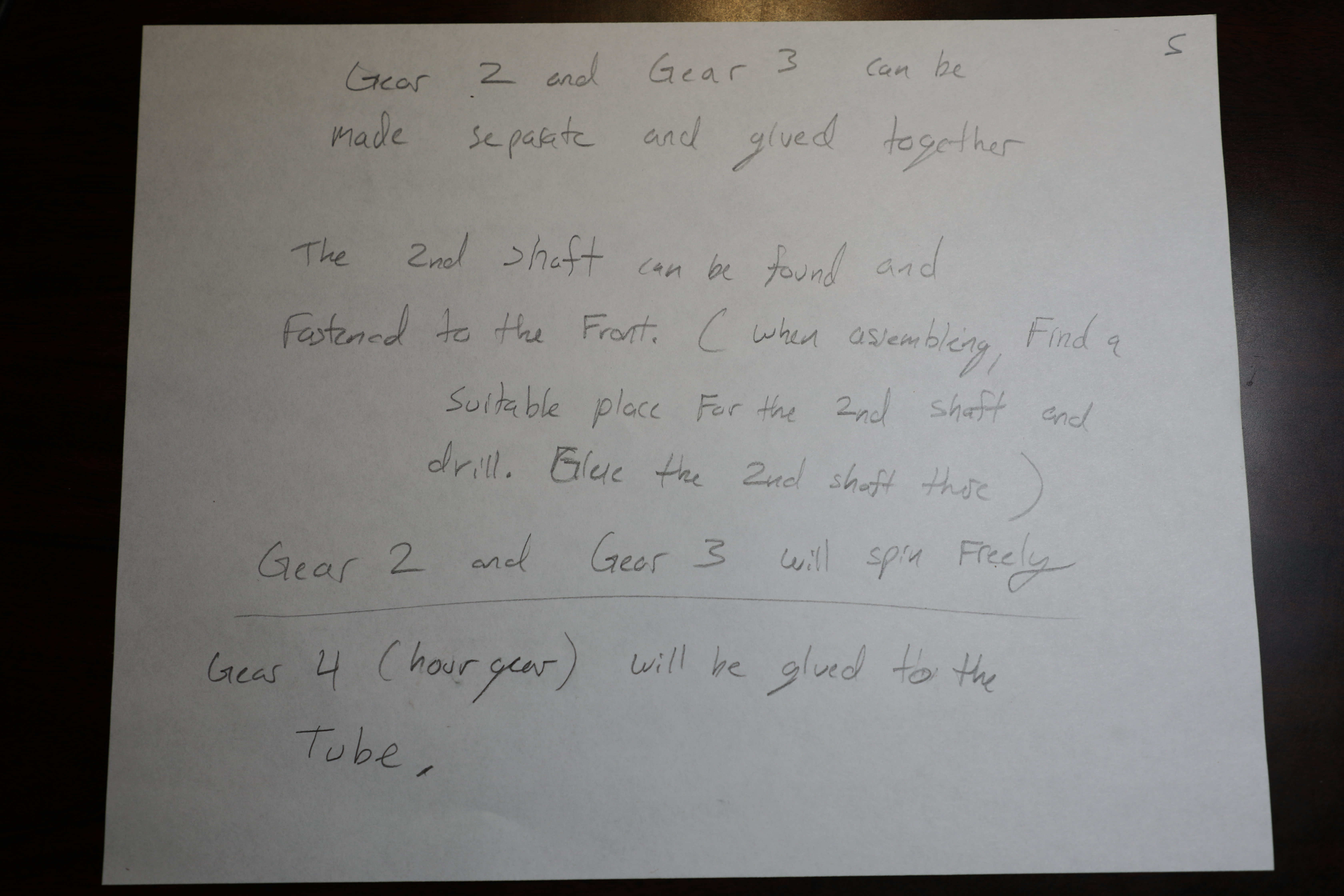
Yesterday, Plans were sketched out for the Design of the Minute hand and the hour hand and the corresponding gears. Such plans are pictured below, 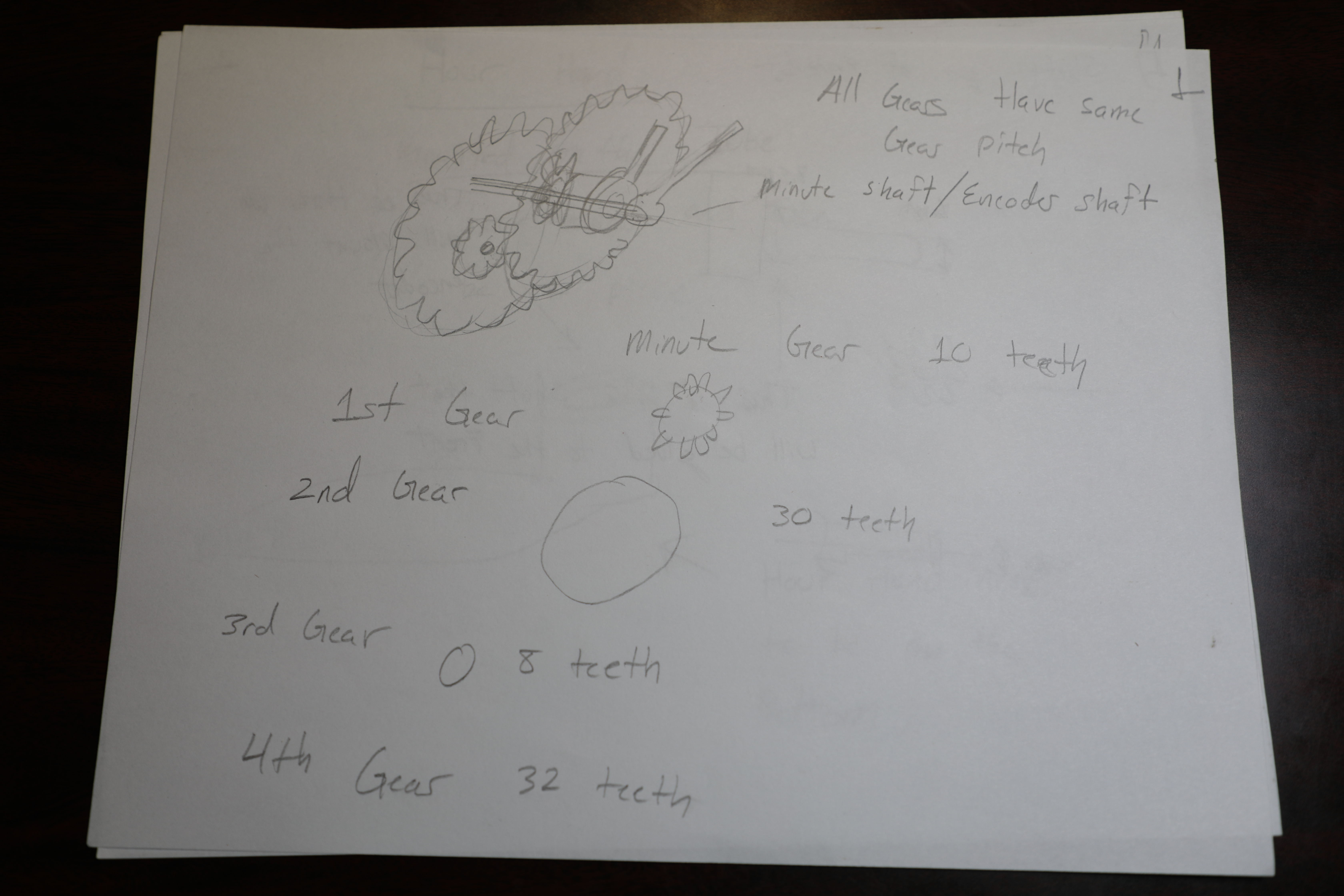
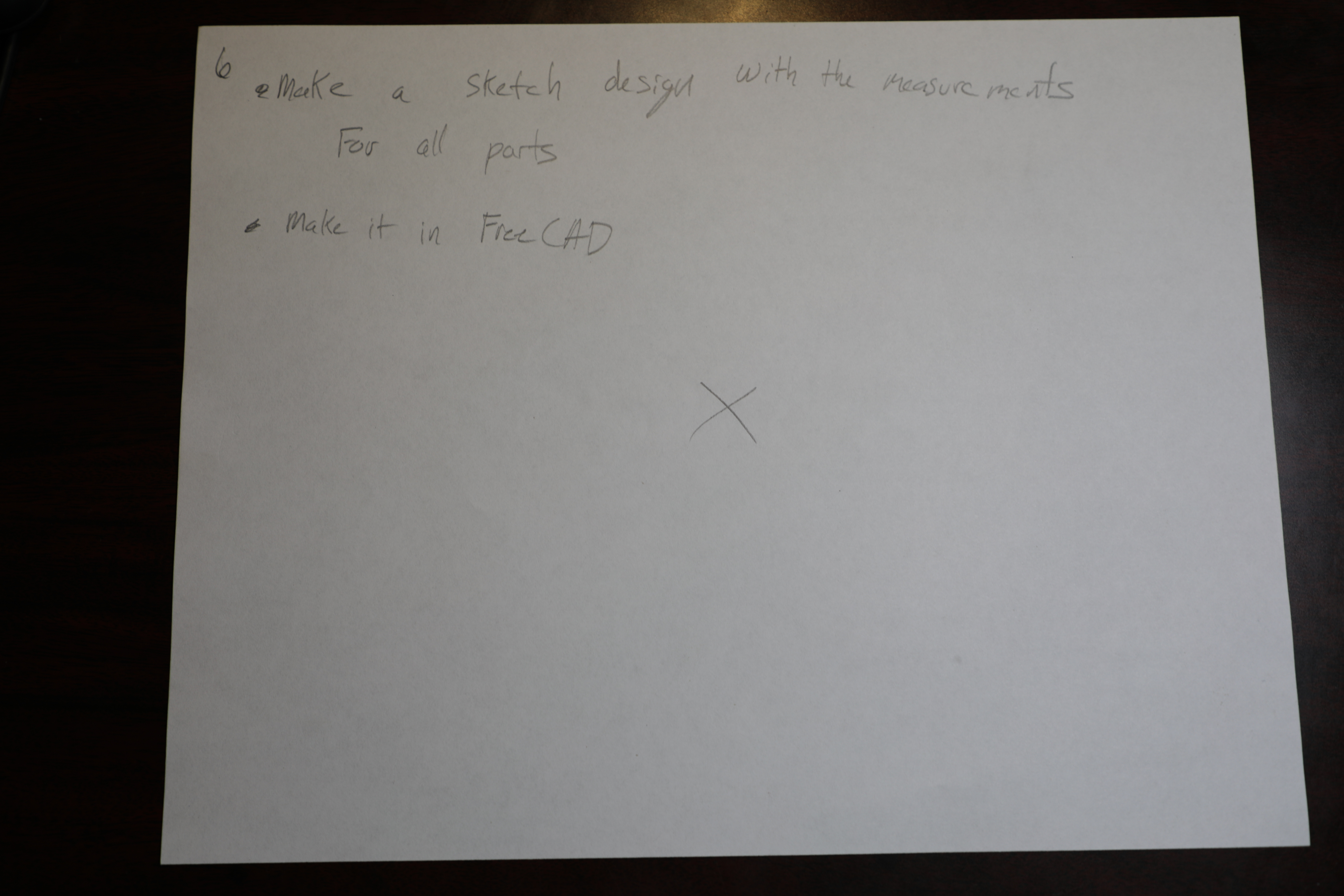
Made a rough sketch of the planning for the electronics encasement of MM1 Minute hand. 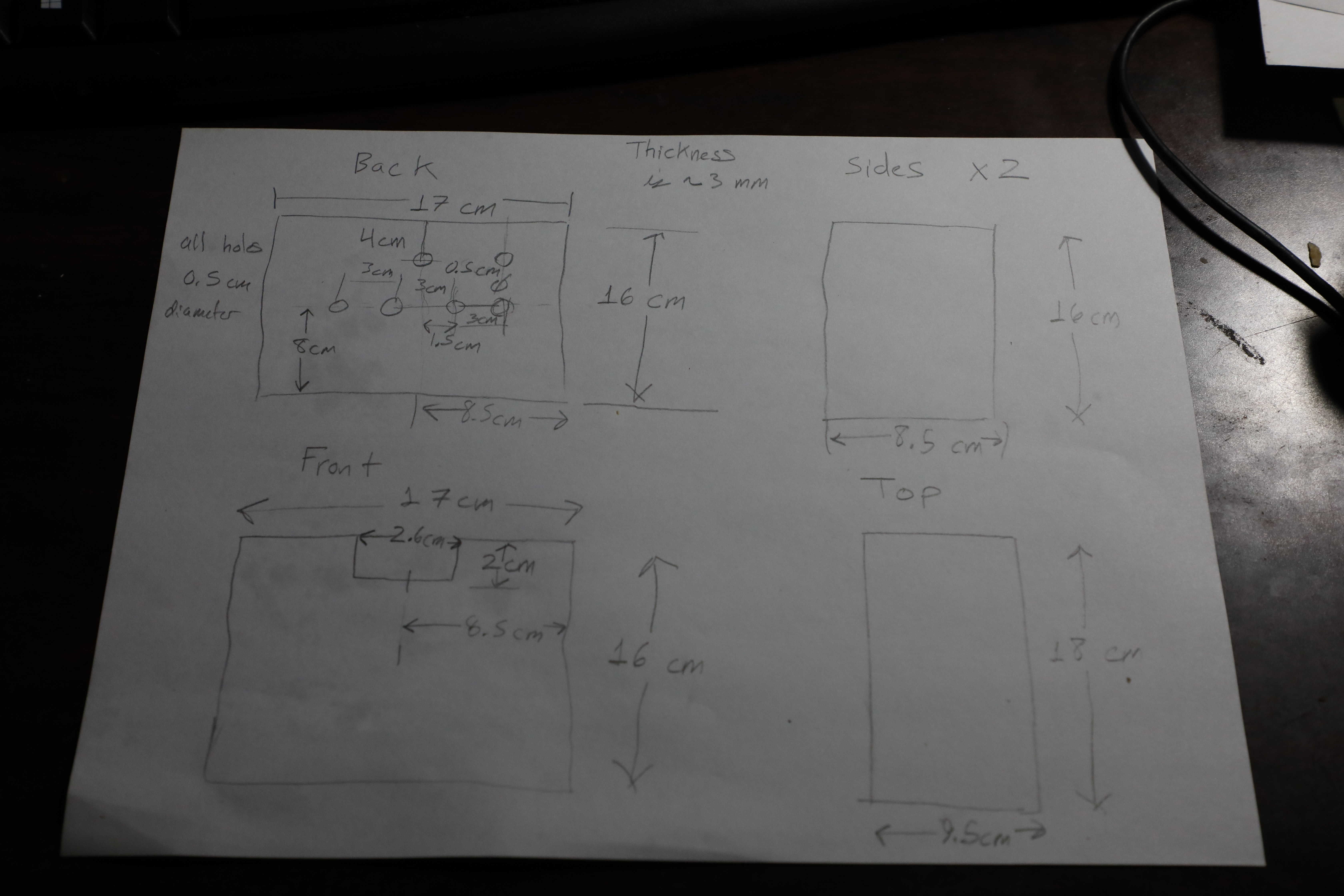
Received Packages yesterday for Testing and construction of the project. 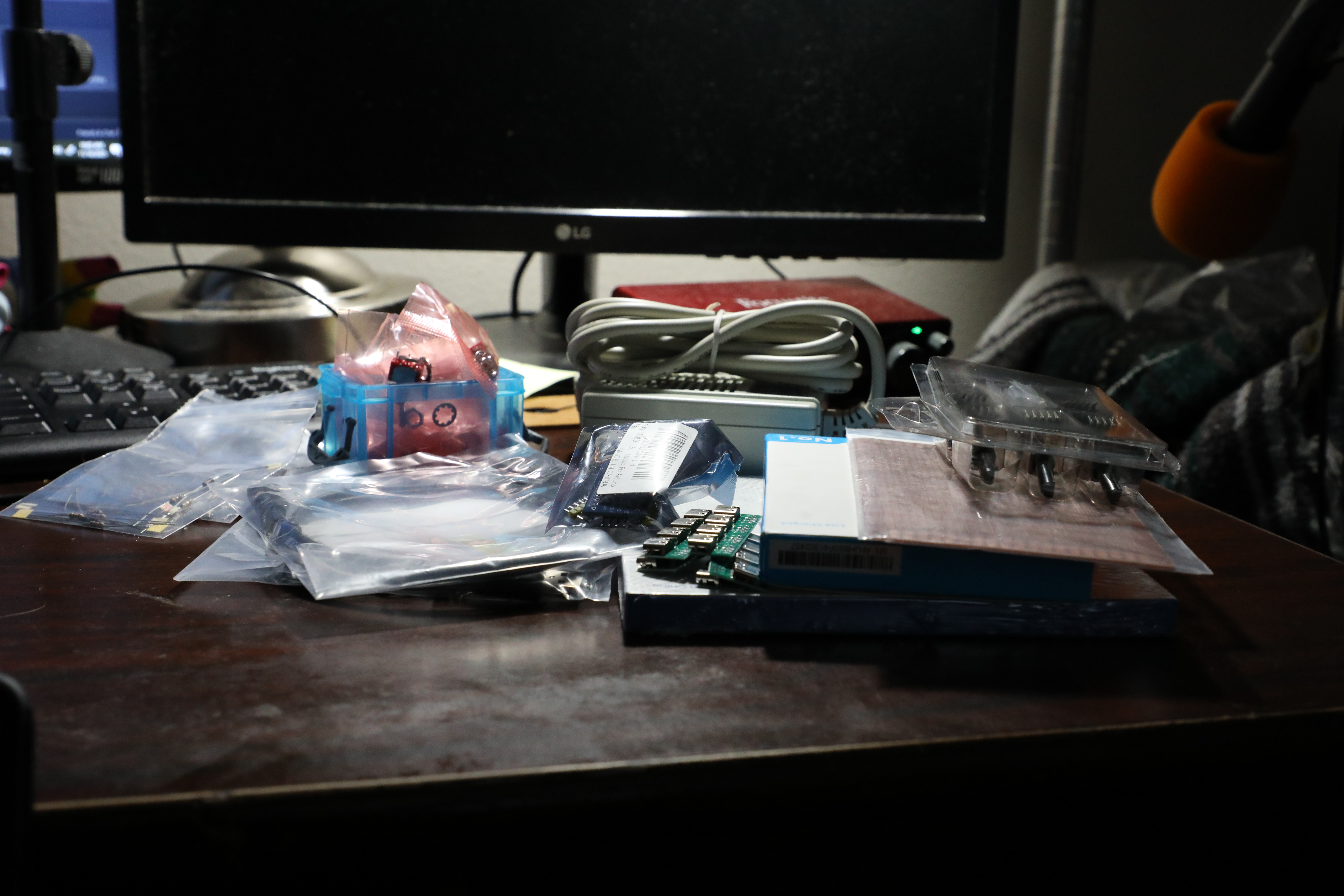
The Electrical Parts were accumulated in a list to order from Amazon and Mouser. The order was placed today November 13.
Researched More items for MM1 Minute Hand which include a portable power bank from Amazon. In addition Orders for a microcontroller and breadboards were also Researched.
researched Parts to order including: USB C cables, female USB C receiver, encoders, SPDT switches, Rechargeable Lead Acid Batteries, LiPo batteries.
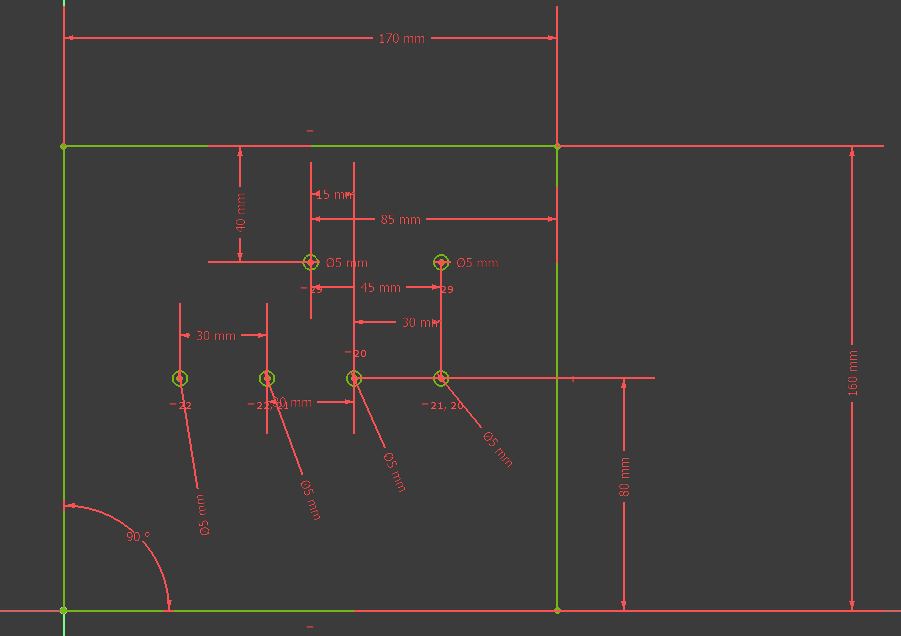
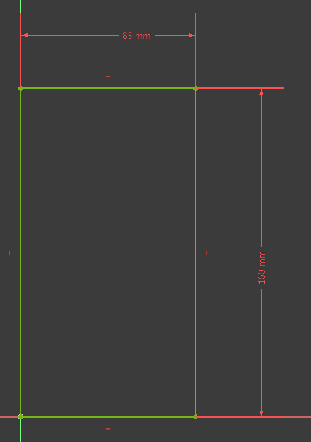
Learned the basics of FreeCAD to design parts for Minute Hand.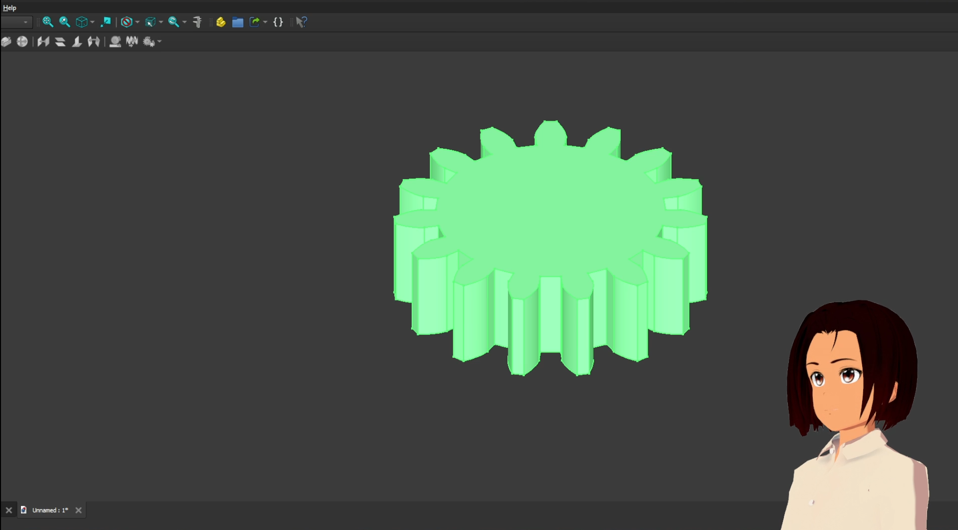
Bought Perf Board, resistors, and a Power Supply for the Main circuit.