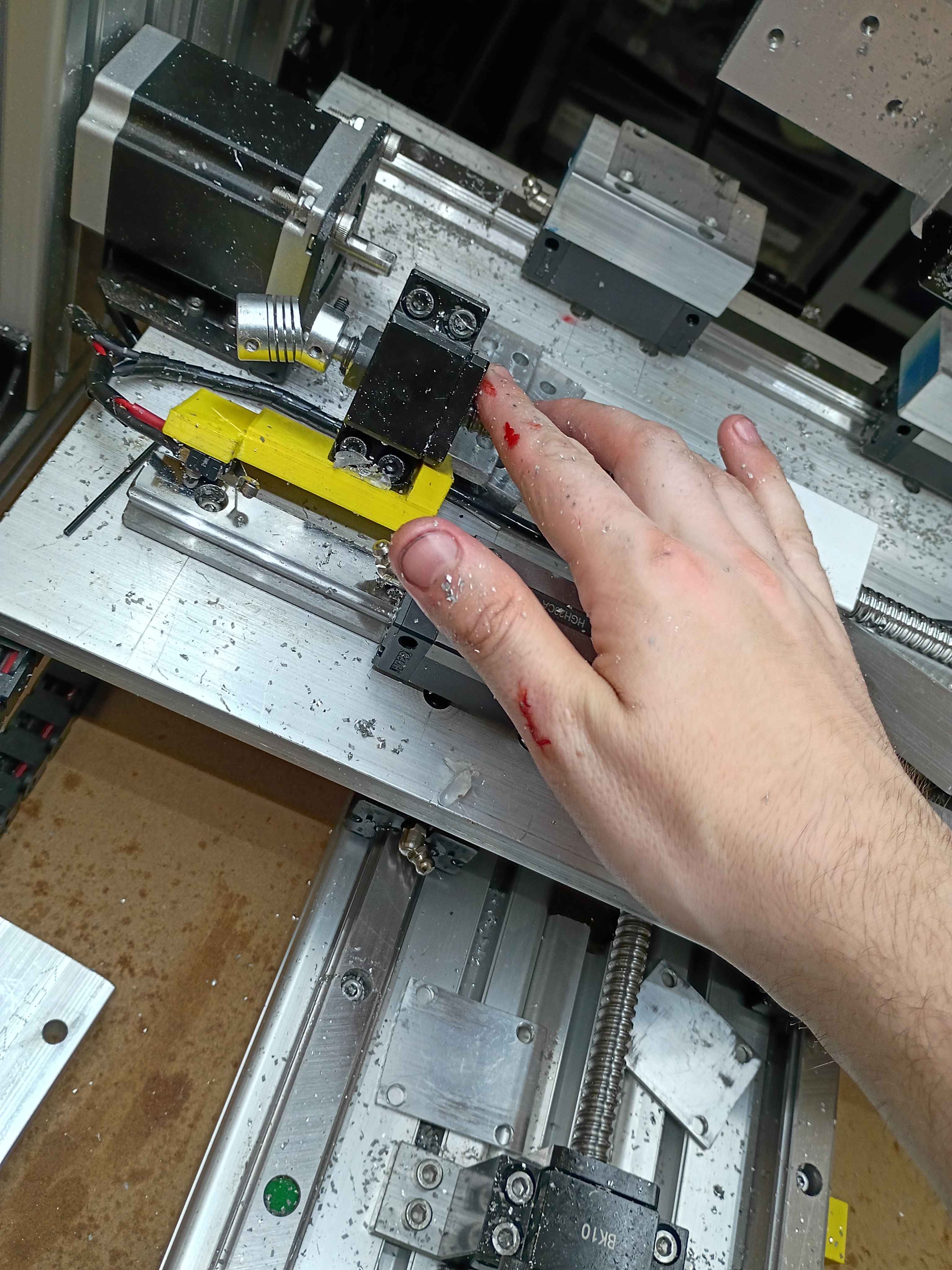
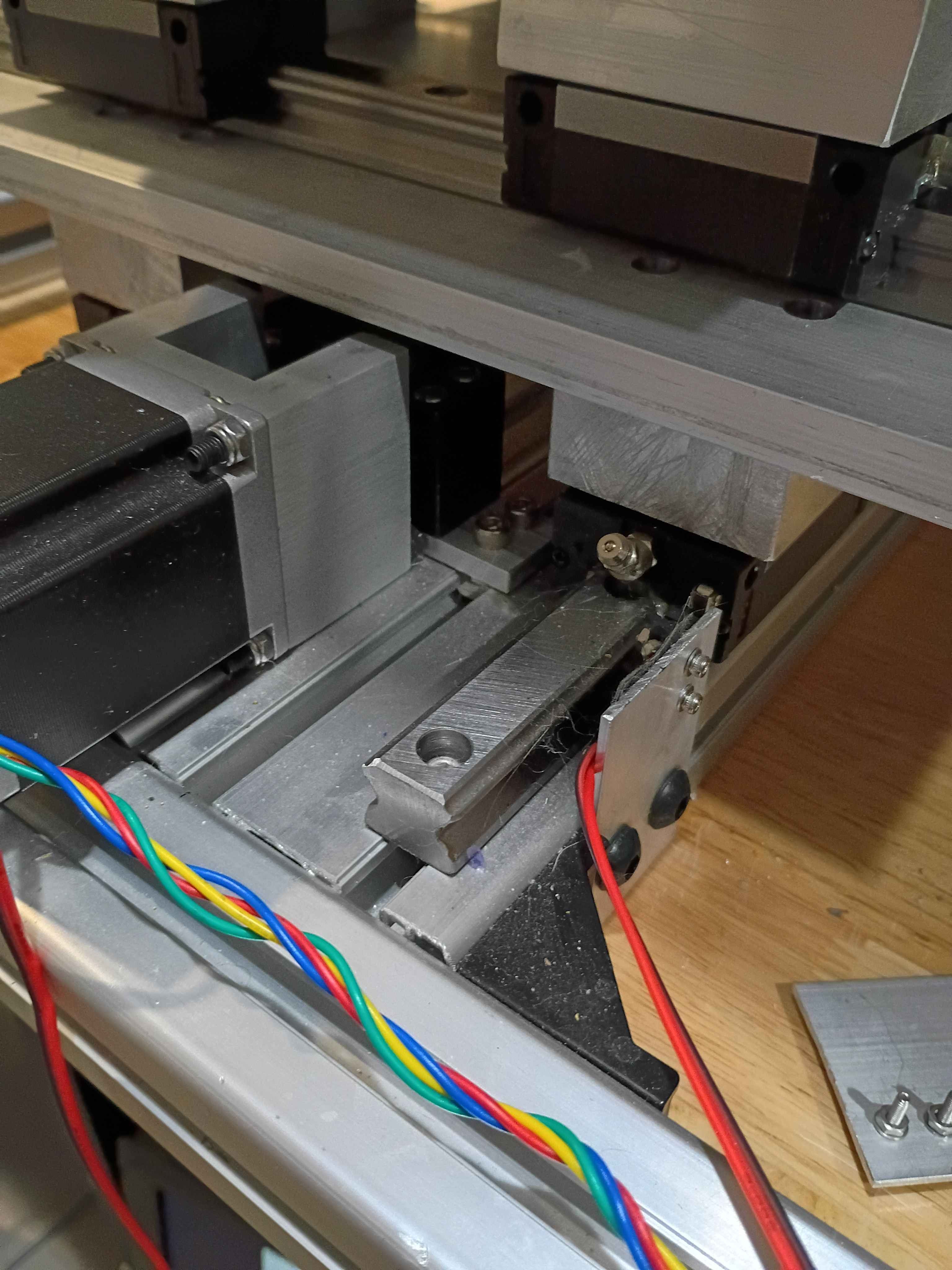
Had to disassemble, repair, and reconstruct the x-axis since the terrible octagonal garbage nut was terrible. Successfully tested afterwards.
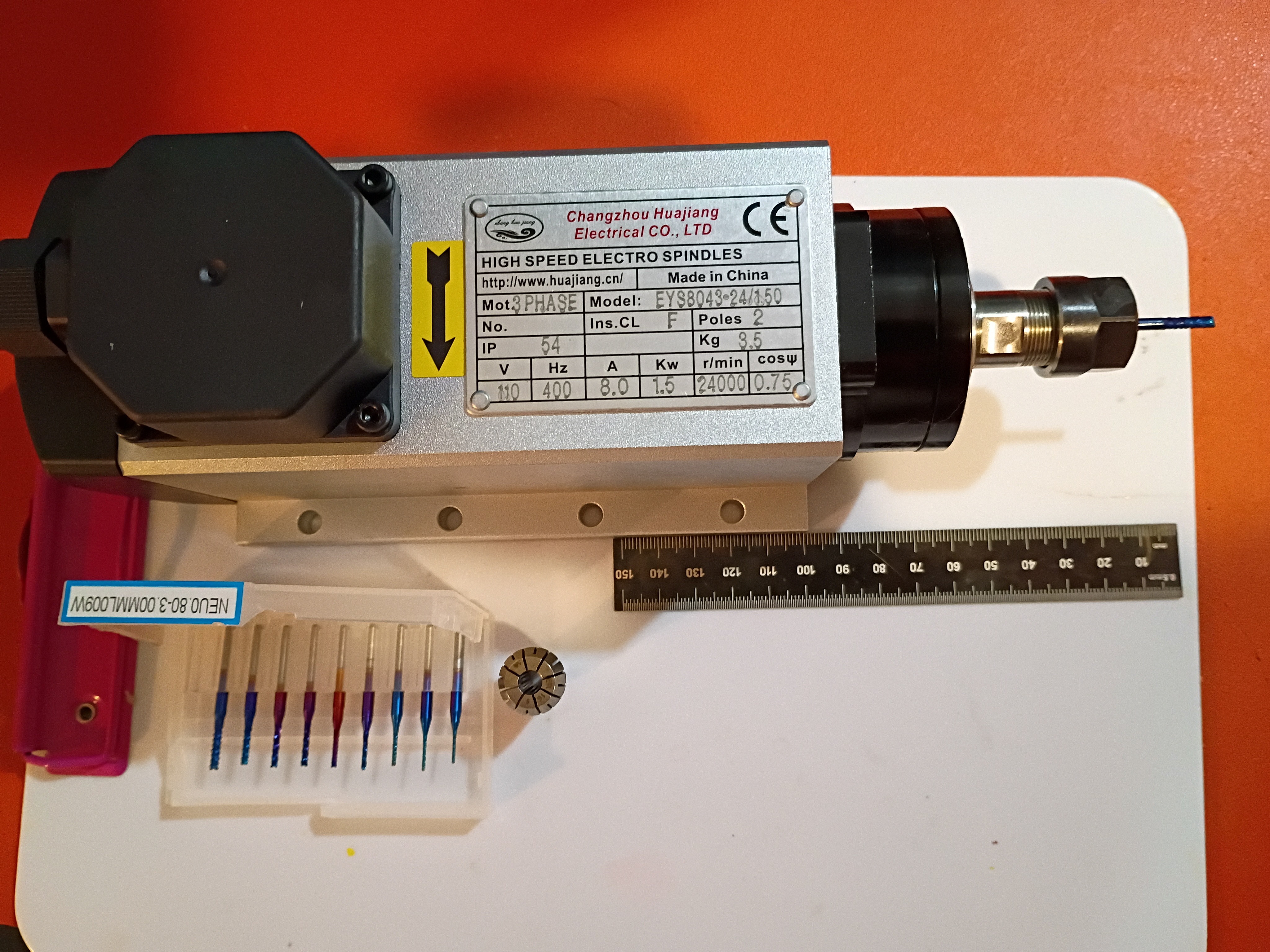
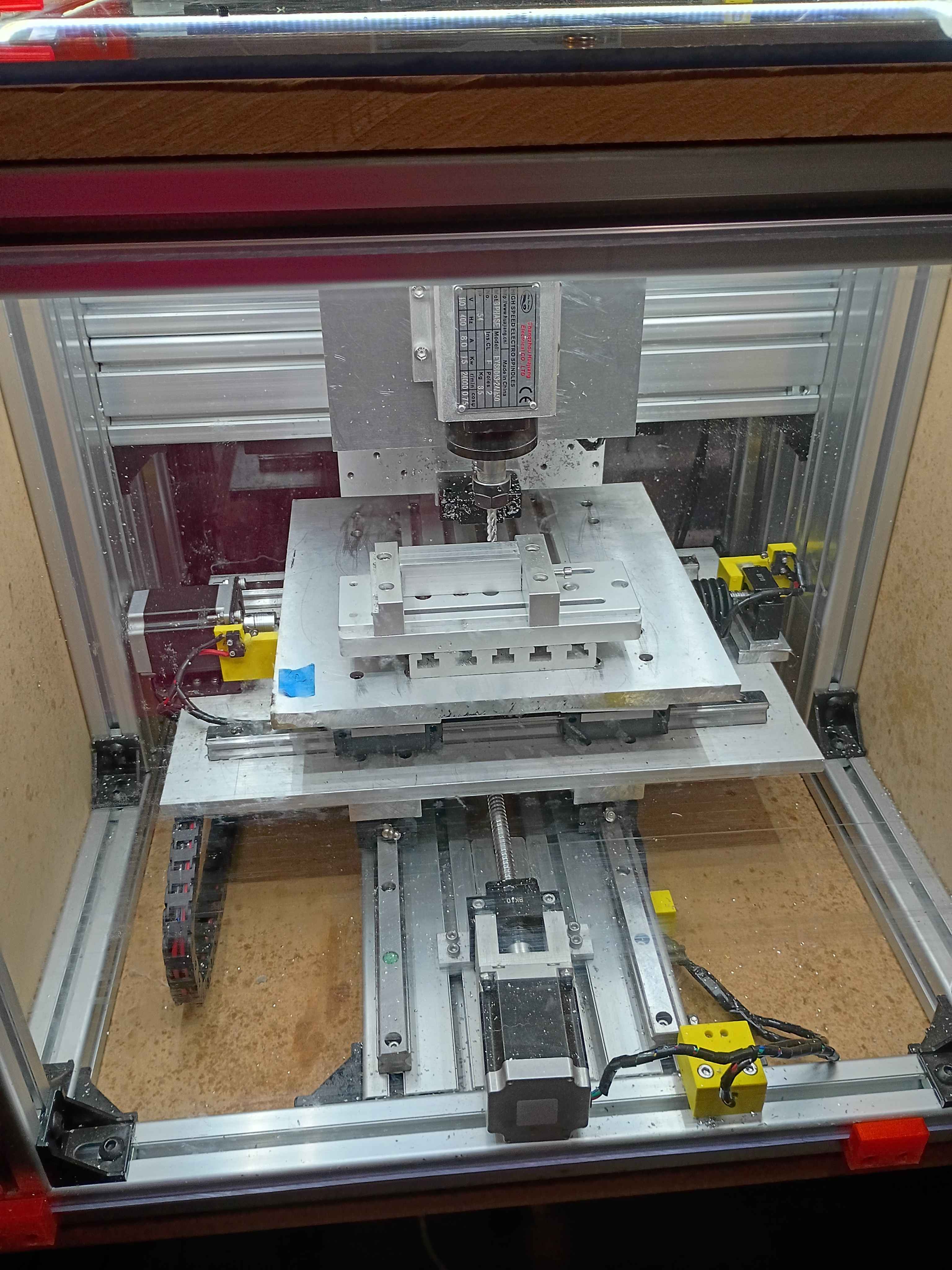
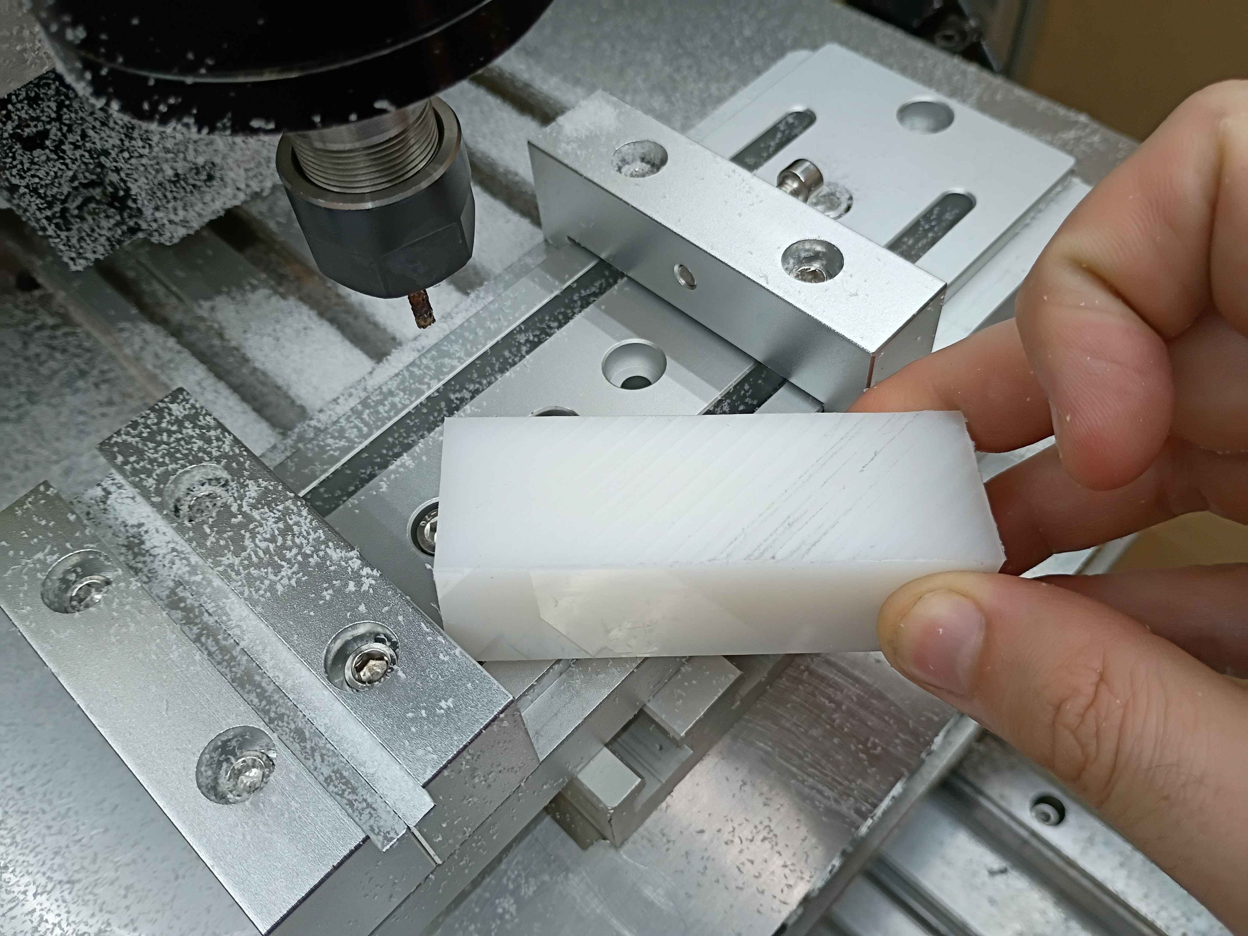
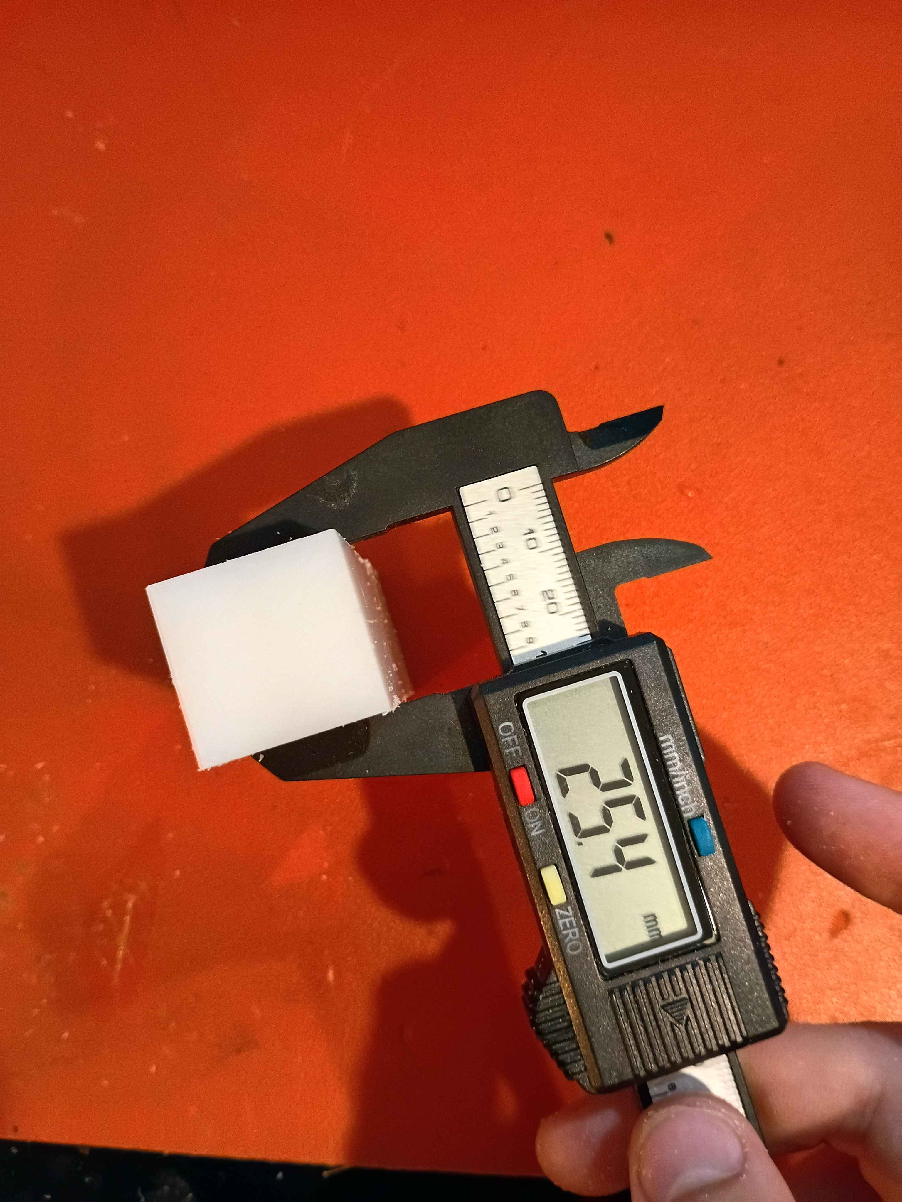
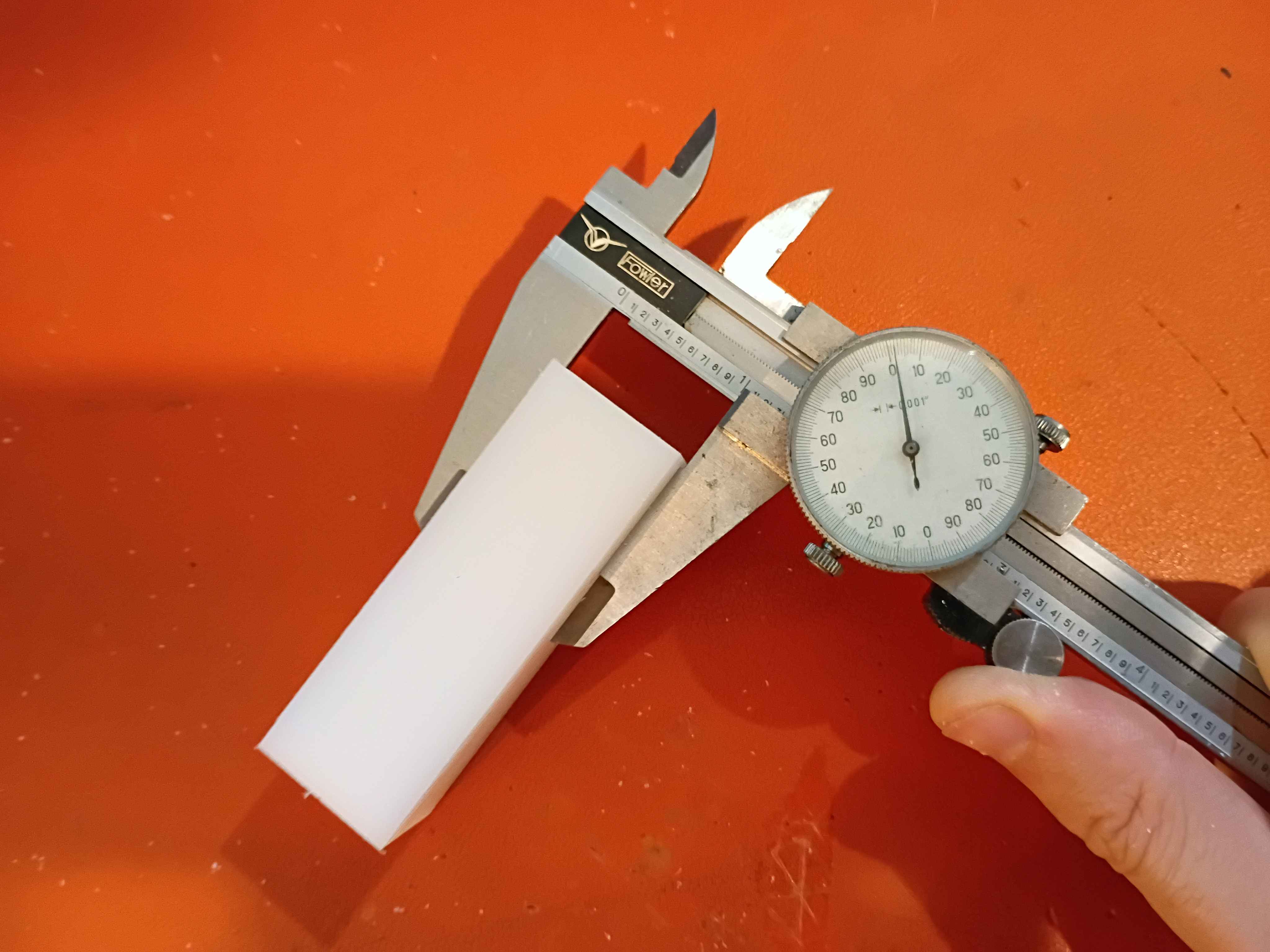
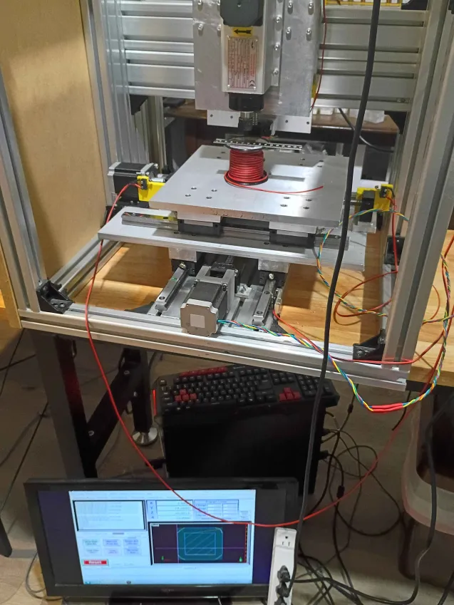
Realized that there is a fundamental flaw in the setup that completely disqualifies a large portion of the y-axis (long axis). There are a couple bandaid fix options for it, and the best are to just drop the vice onto the gantry plate, reduce the Z axis ballscrew length, or just avoid large swaths of the milling volume. Was able to face the top of a 1x1x3" piece of HDPE within .001 (although that's more a measure of how well I was able to guestimate Z-zero position of the top of the material. The total variation across the part was .000 to .002. It cut well but produced a lot of HDPE dust because I was using a PCB drill instead of an endmill for fear of breaking something more valuable on the first real milling attempt. I was cutting a 30 mm/min and 100 Hz with a 1/8" PCB drill, which corresponds to around 5000RPM. I learned a lot about how to use the MachCNC software. See video. 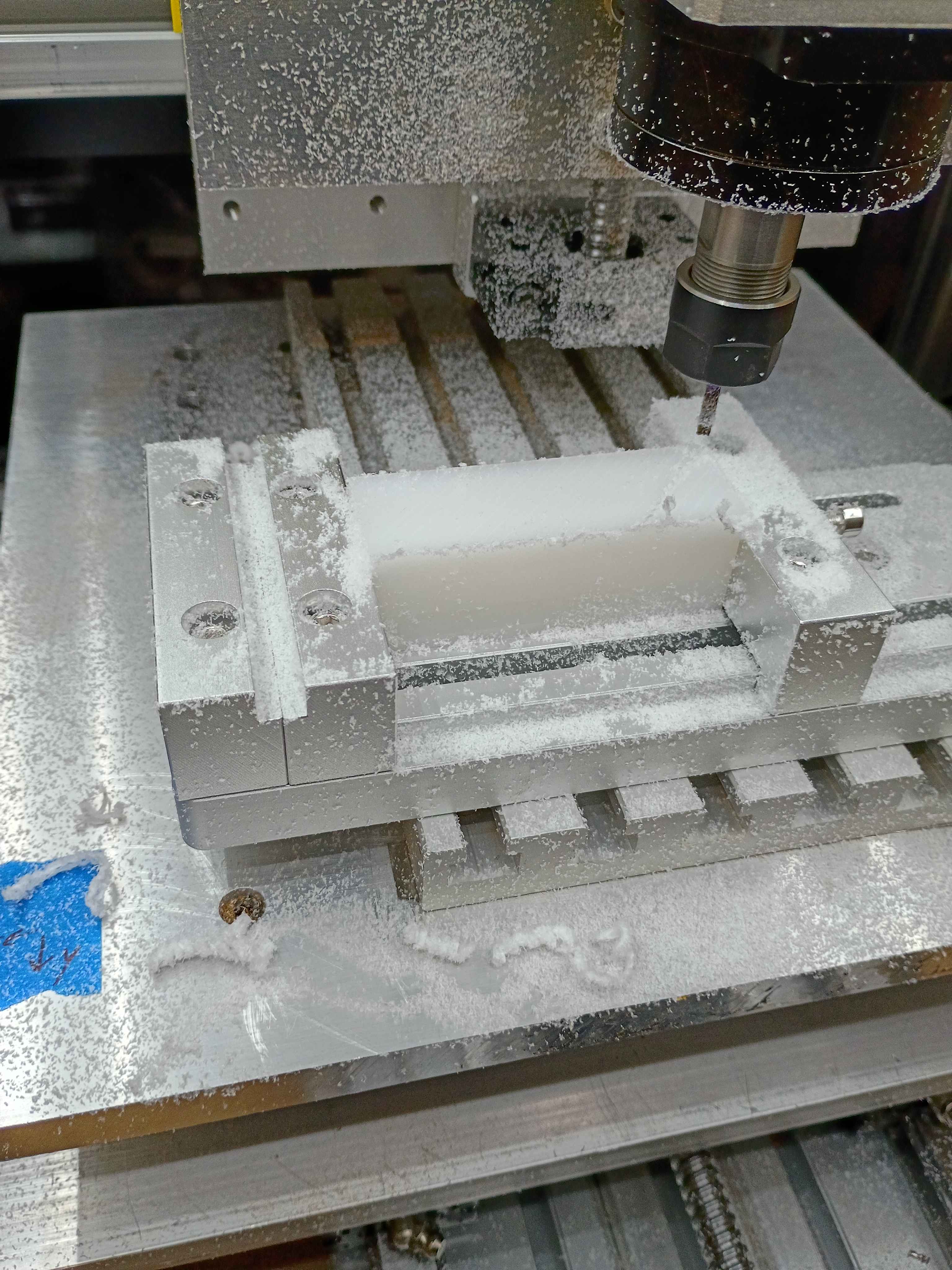
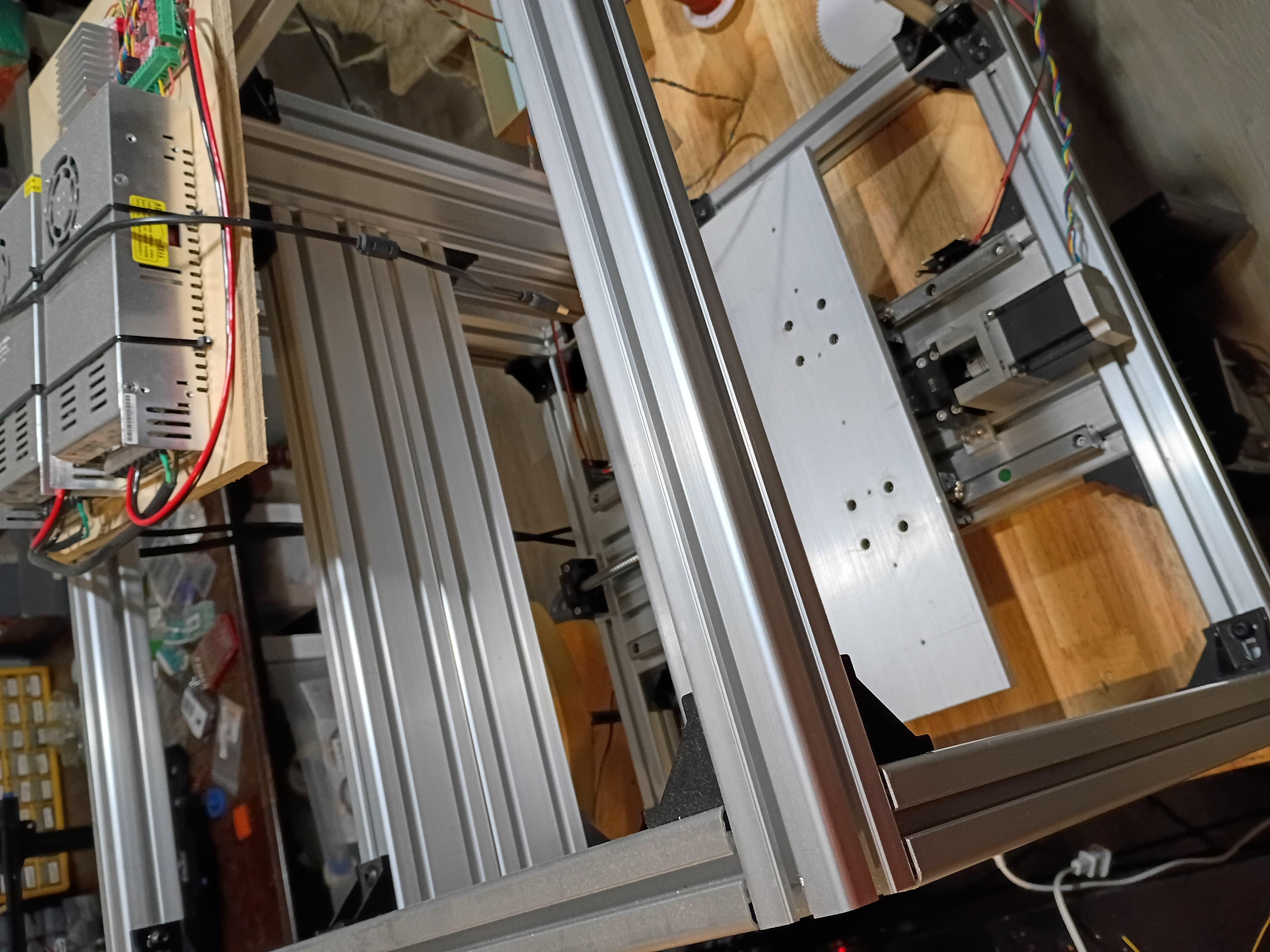
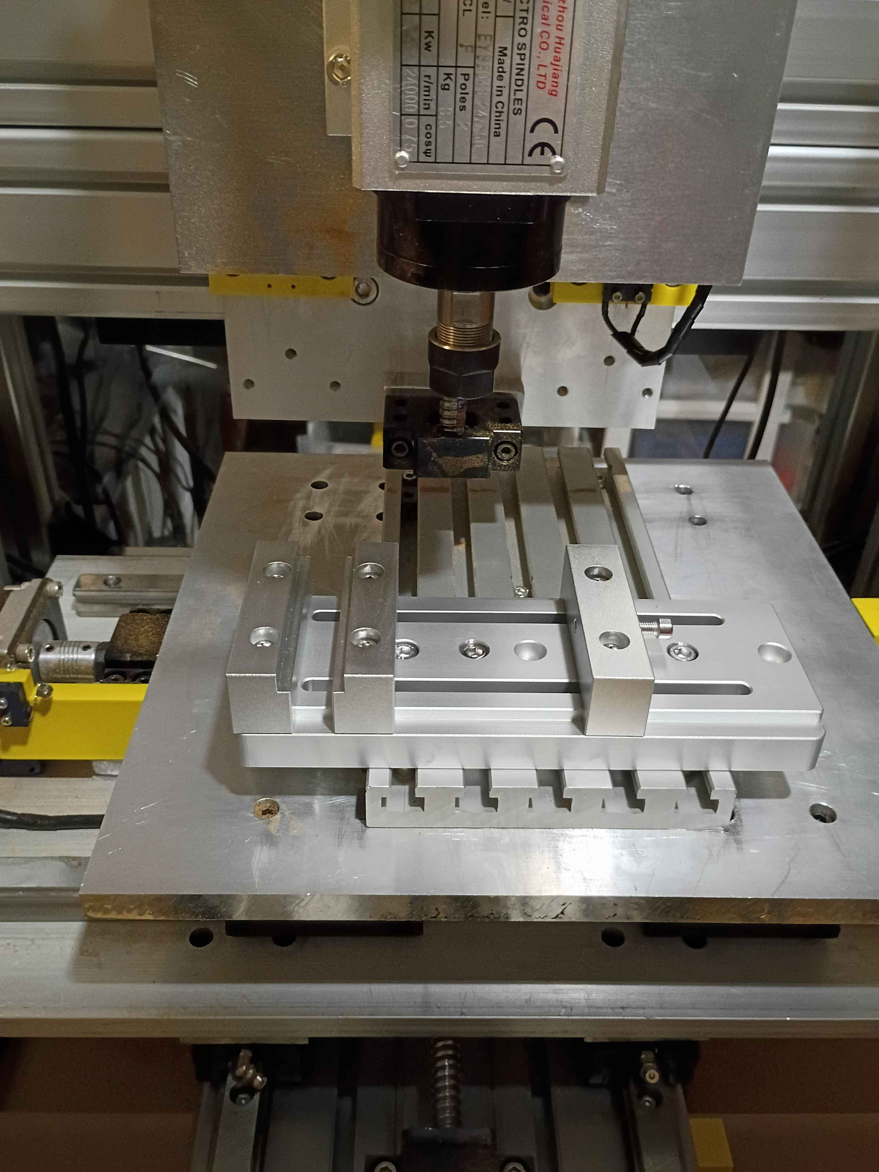
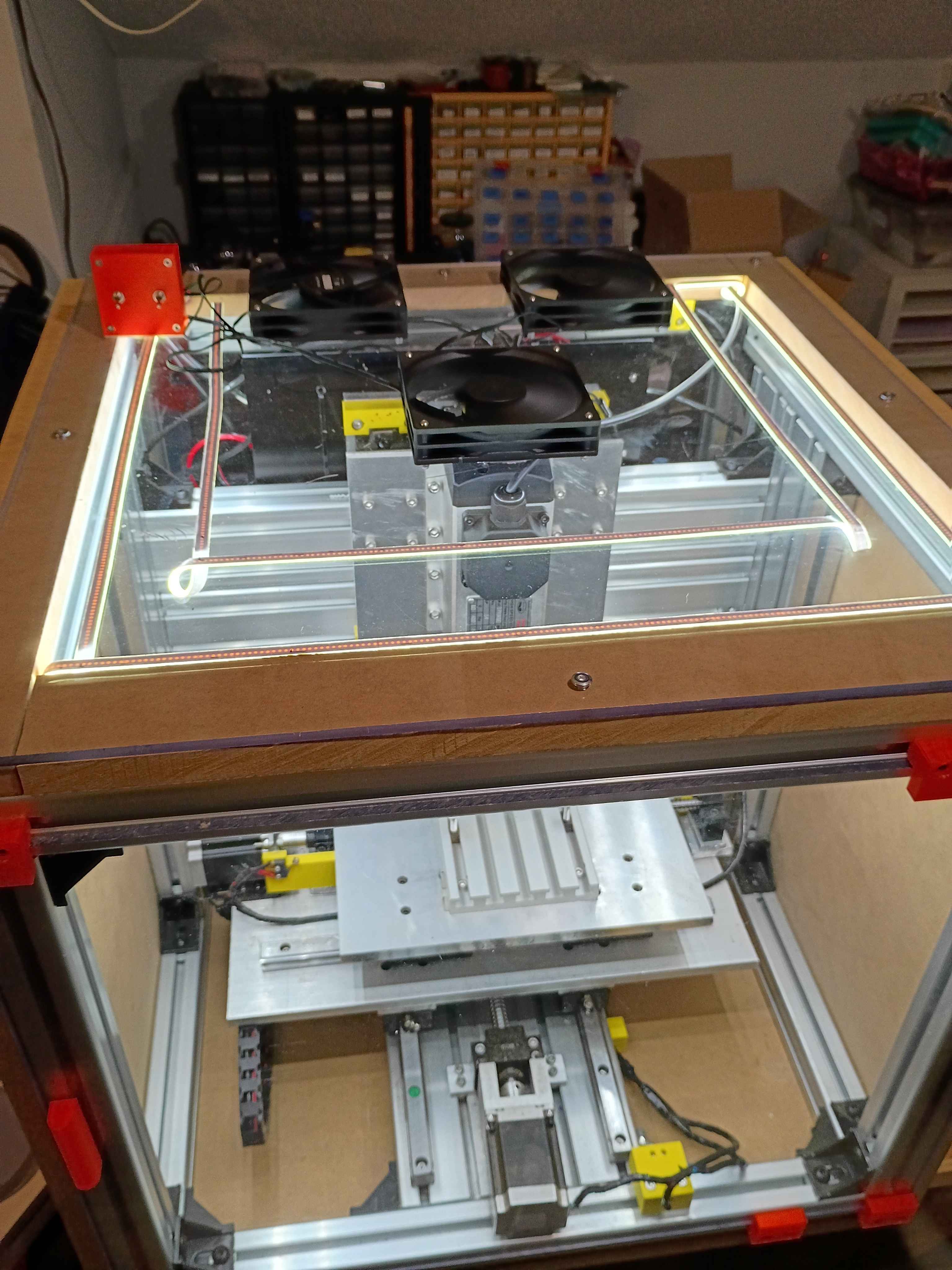
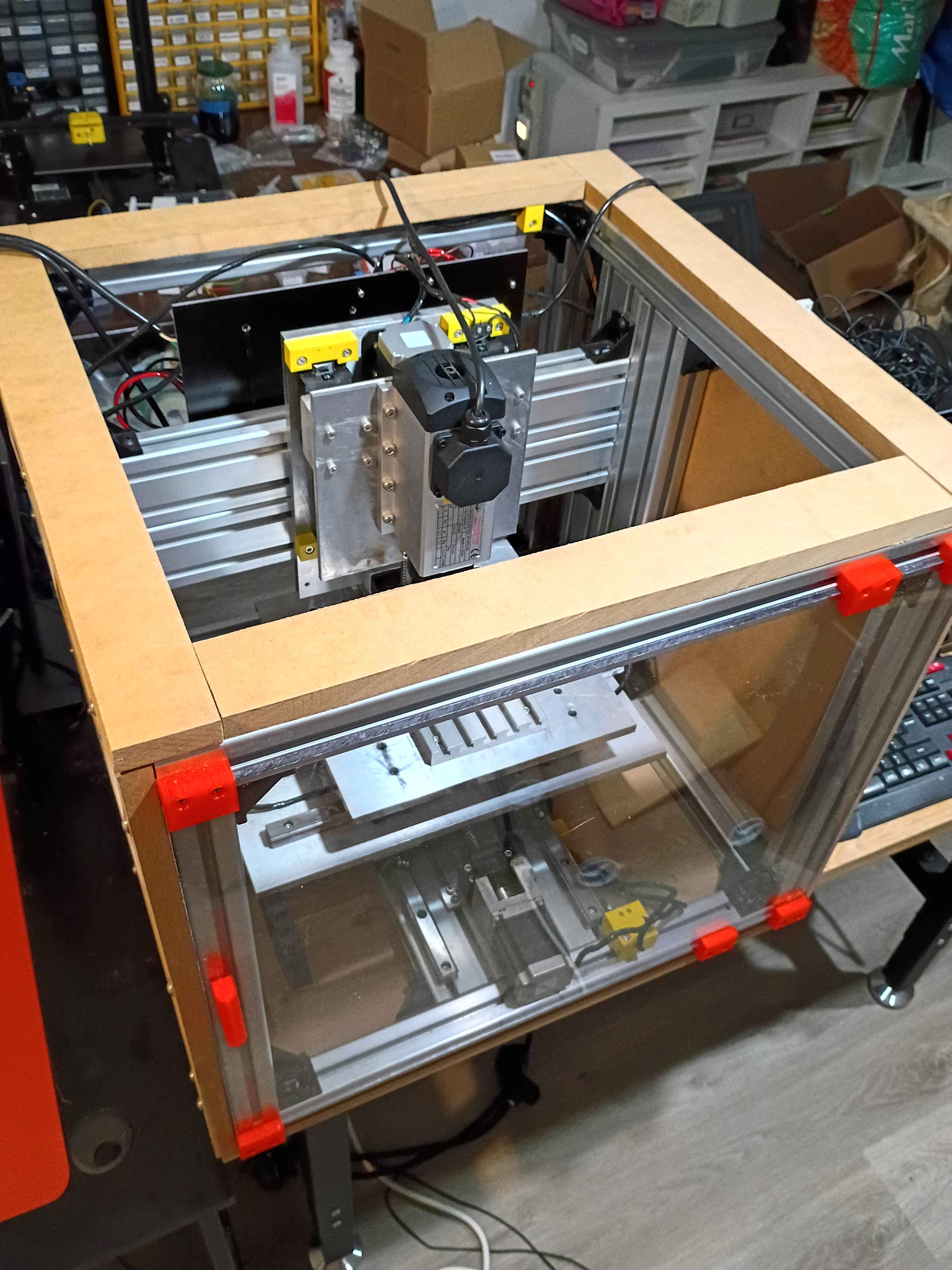
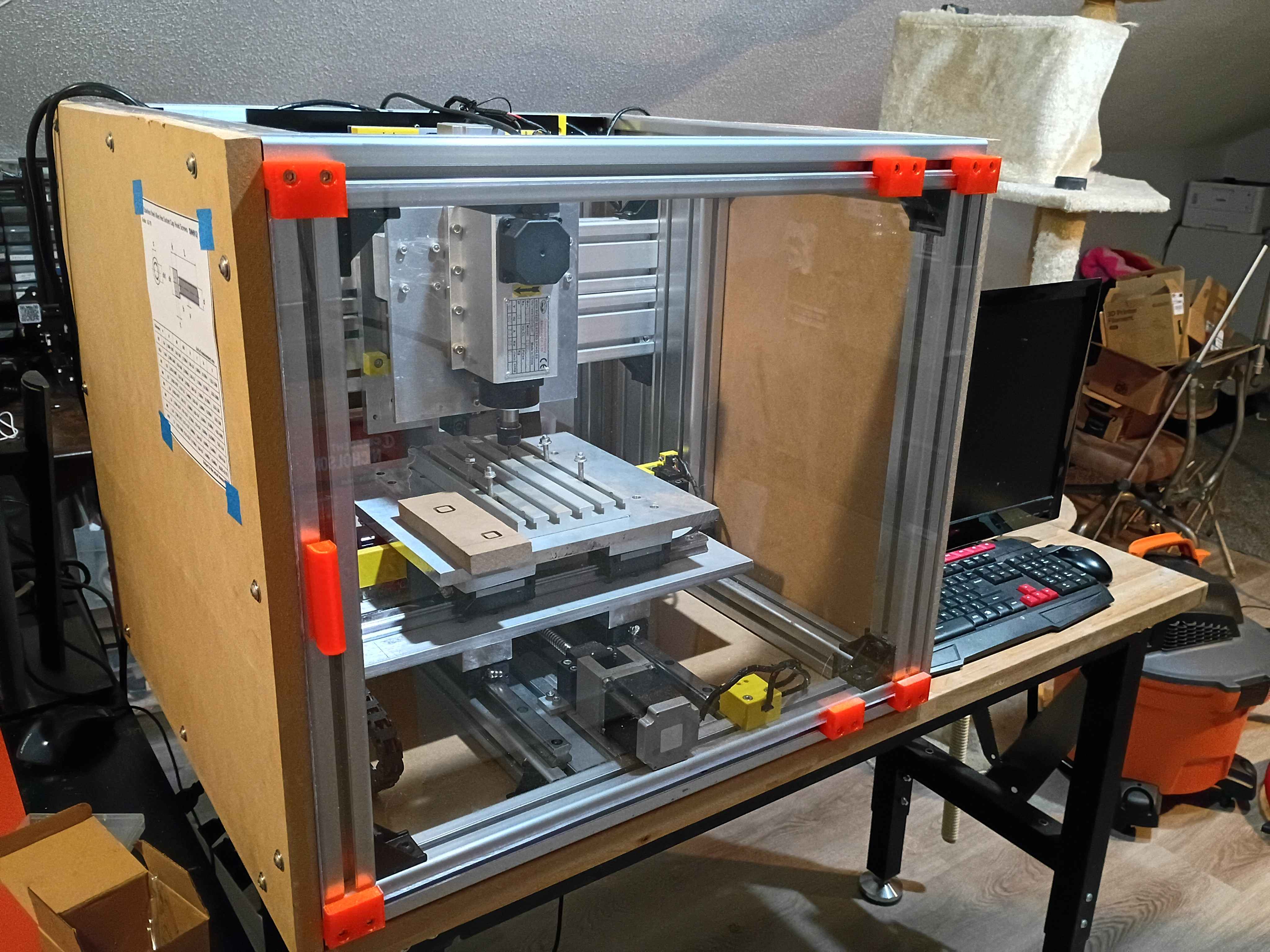
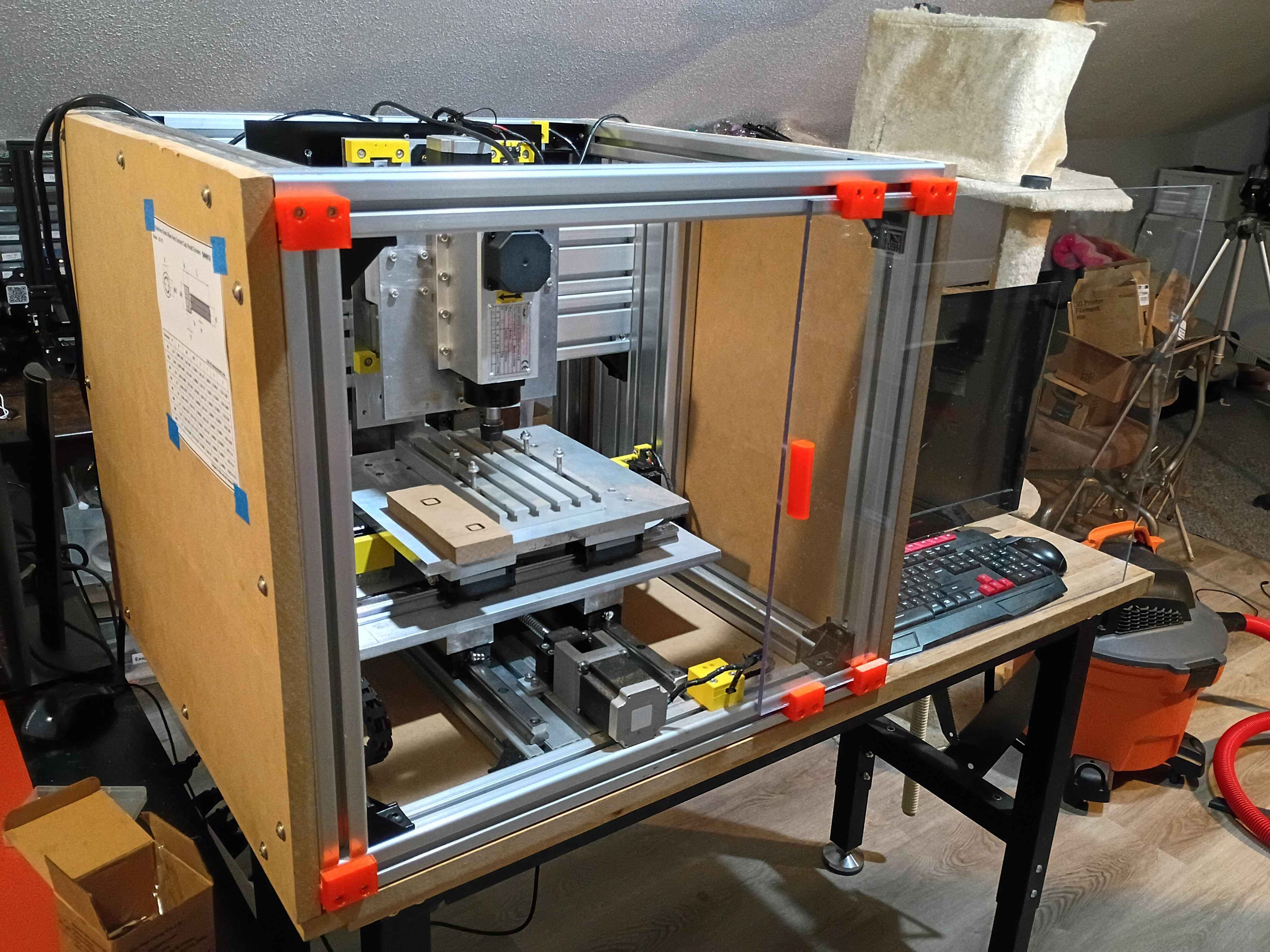
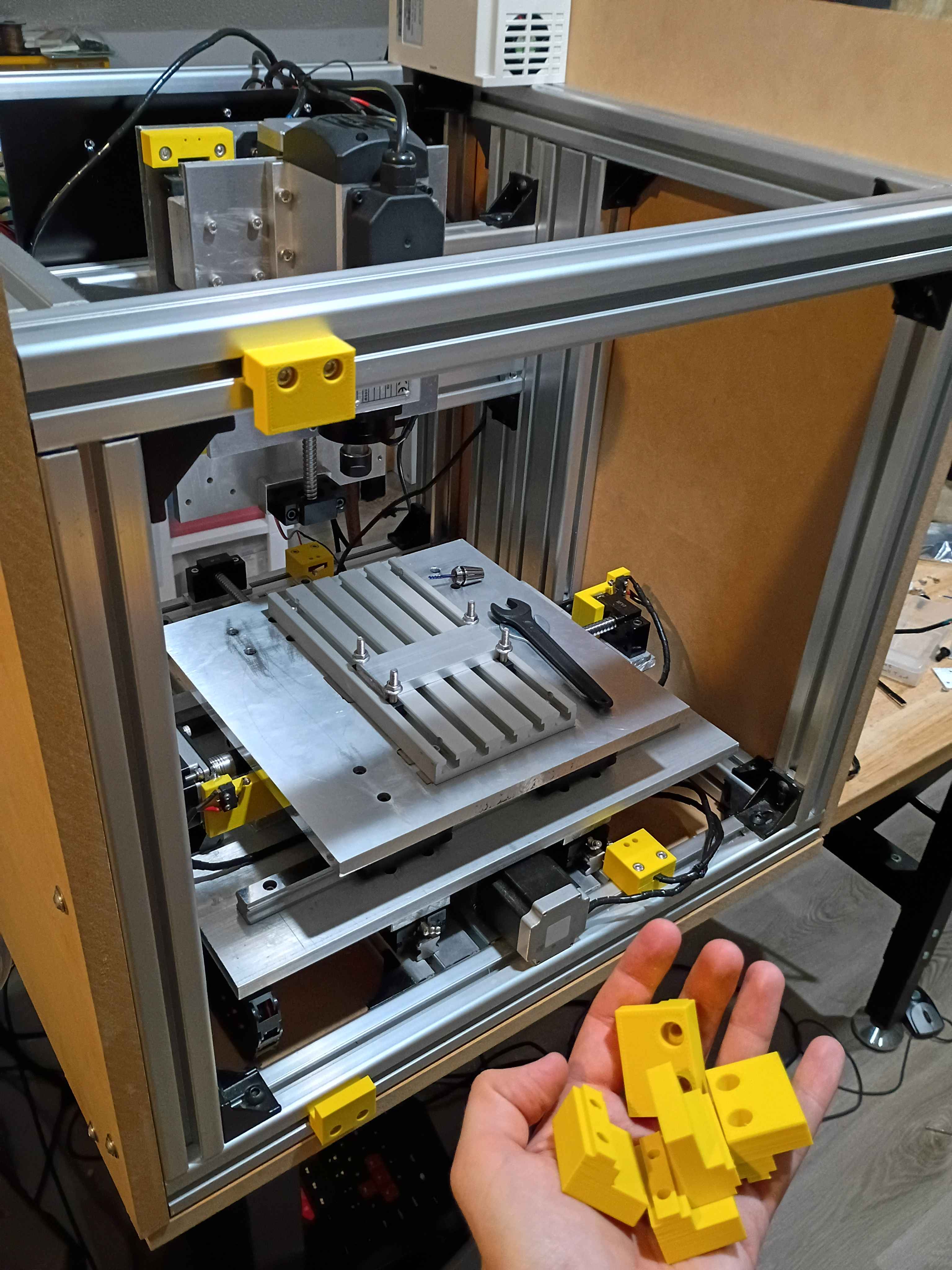
Received and mounted new 8A 12V power supply for the lights, which makes them way brighter, not overheat the power supply, not flicker out occasionally, and not dim the lights when turning on the fans. Also received the new machining vice and drilled (and counterbored) 3 new holes with a 1" spacing. Mounted up everything successfully, and ready for a test run tomorrow. The only caveat is that technically the vice is able to run into some of the z-axis components if the user is not careful, so that is a design flaw in the entire z axis setup. 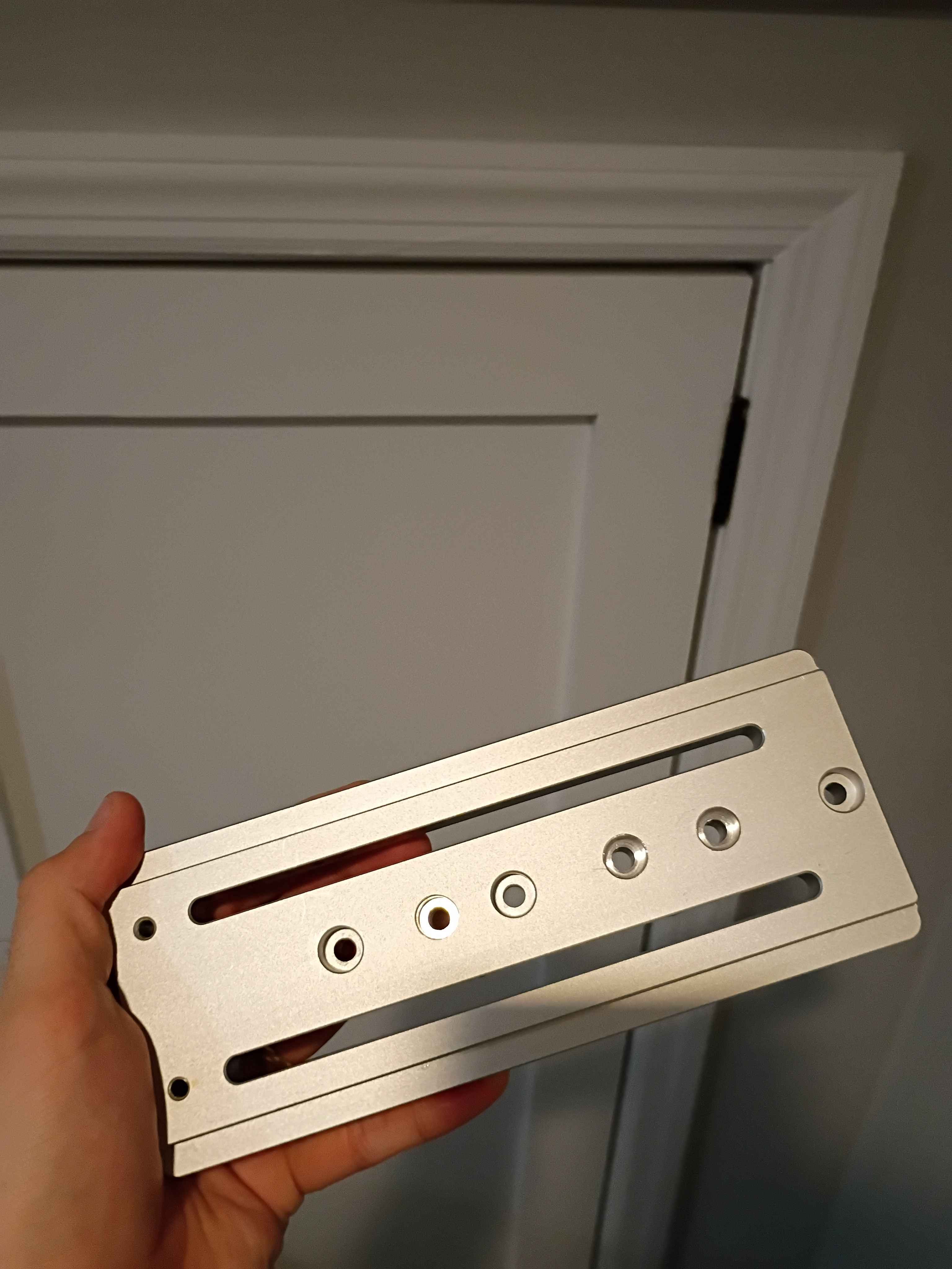
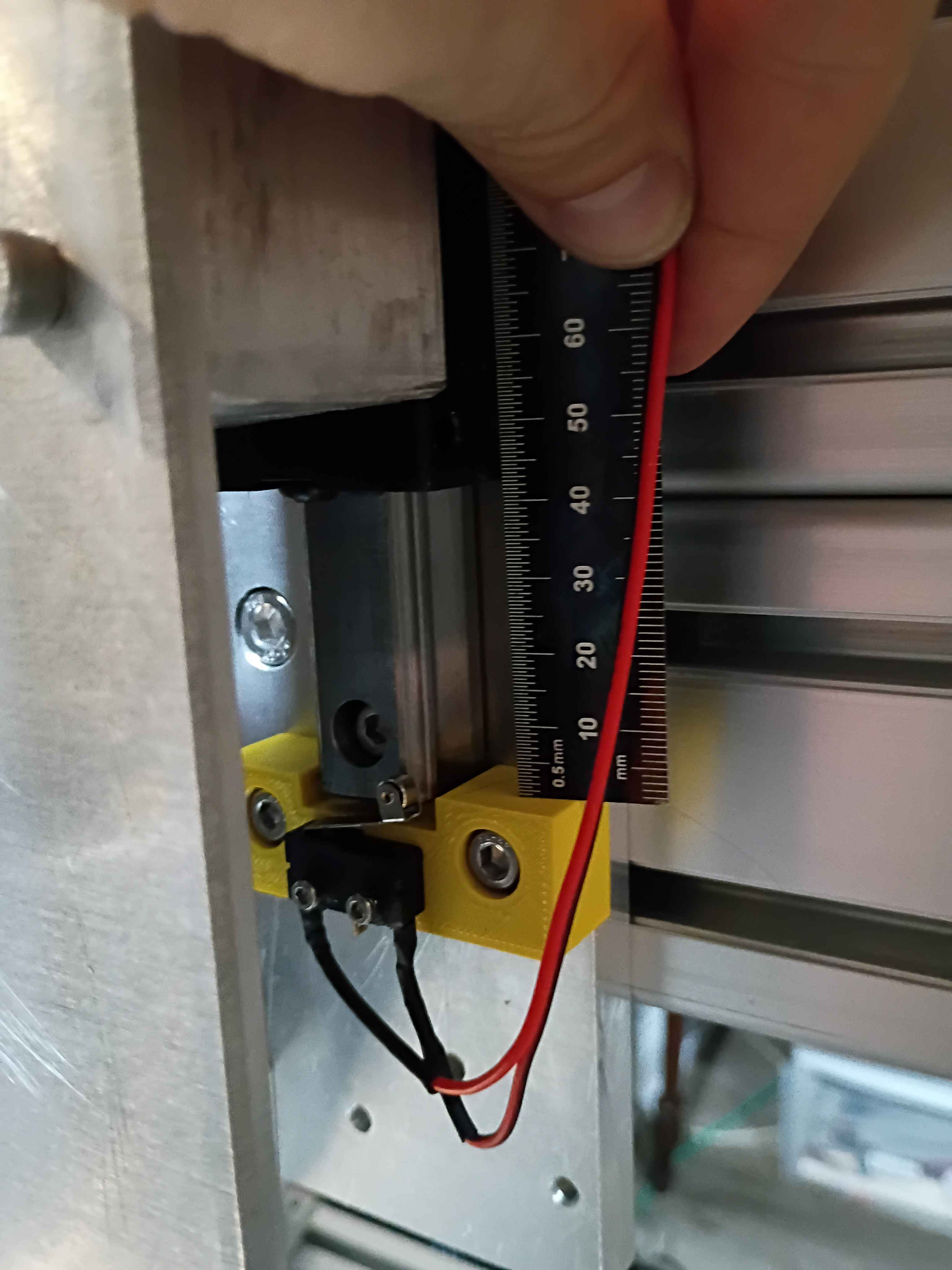
Determined Z-axis range of motion and purchased a clamp that allows for most of the use of the range, though it will require some extra mounting holes drilled into it. Also purchased some bellows to protect the ballscrews. 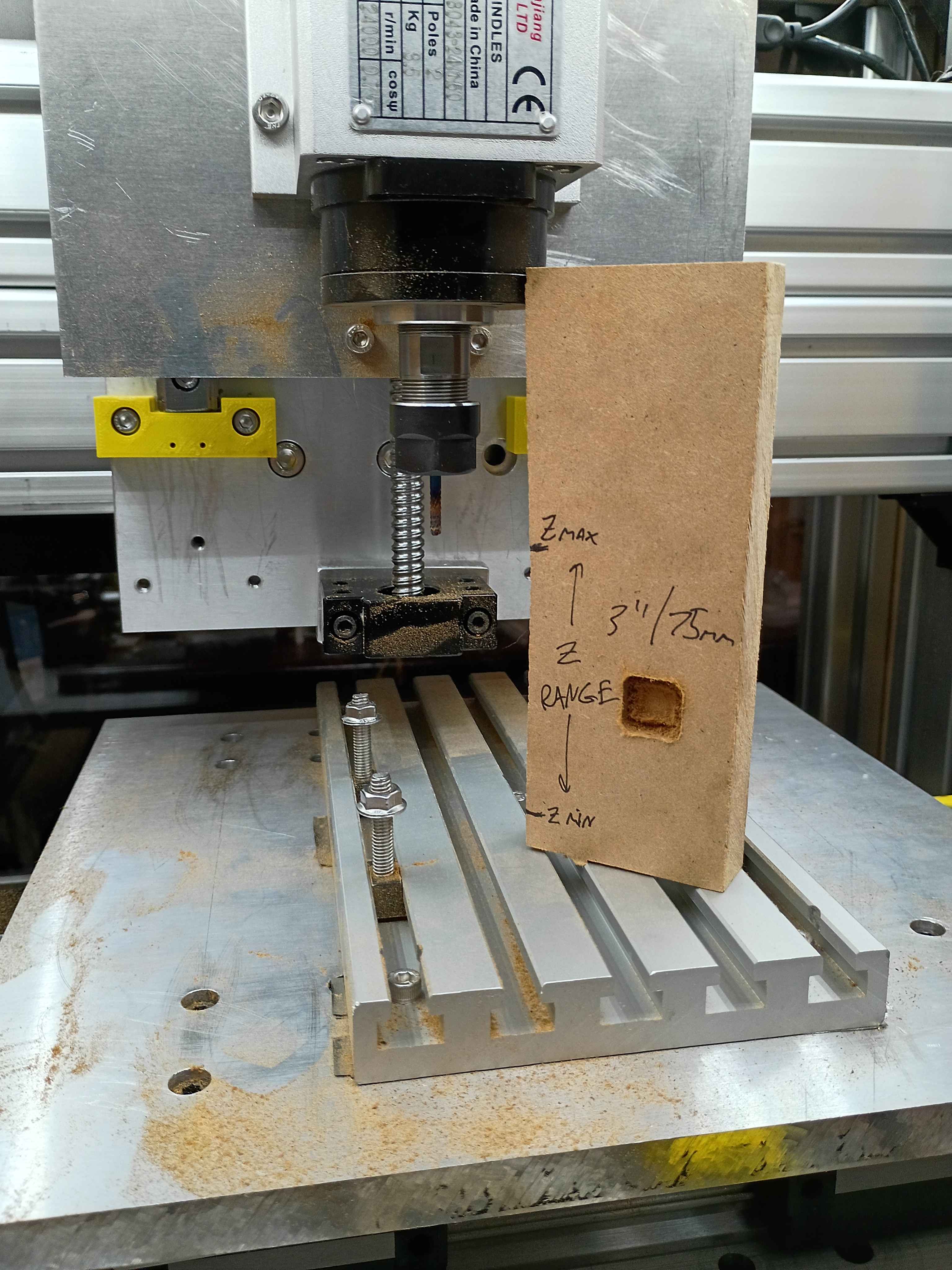
Conducted more tests on the CNC. Depth does seem to work properly, except that I run out of travel downwards in some situations. Can possibly be resolved with different fixturing setup. Also realized the 12V power supply I had on hand does not provide enough amps for 3 fans and the lighting in parallel. Ordered a more powerful replacement. 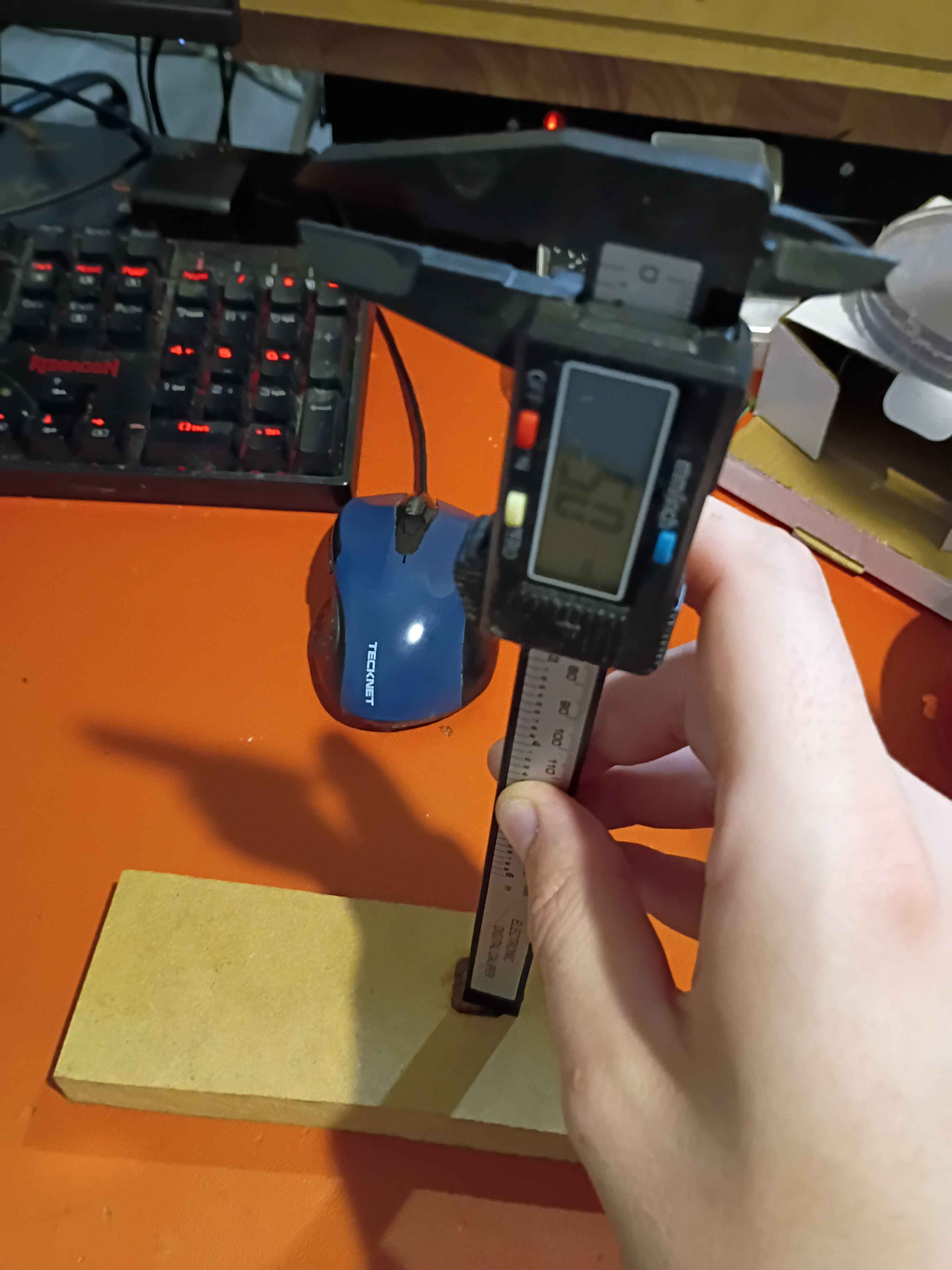
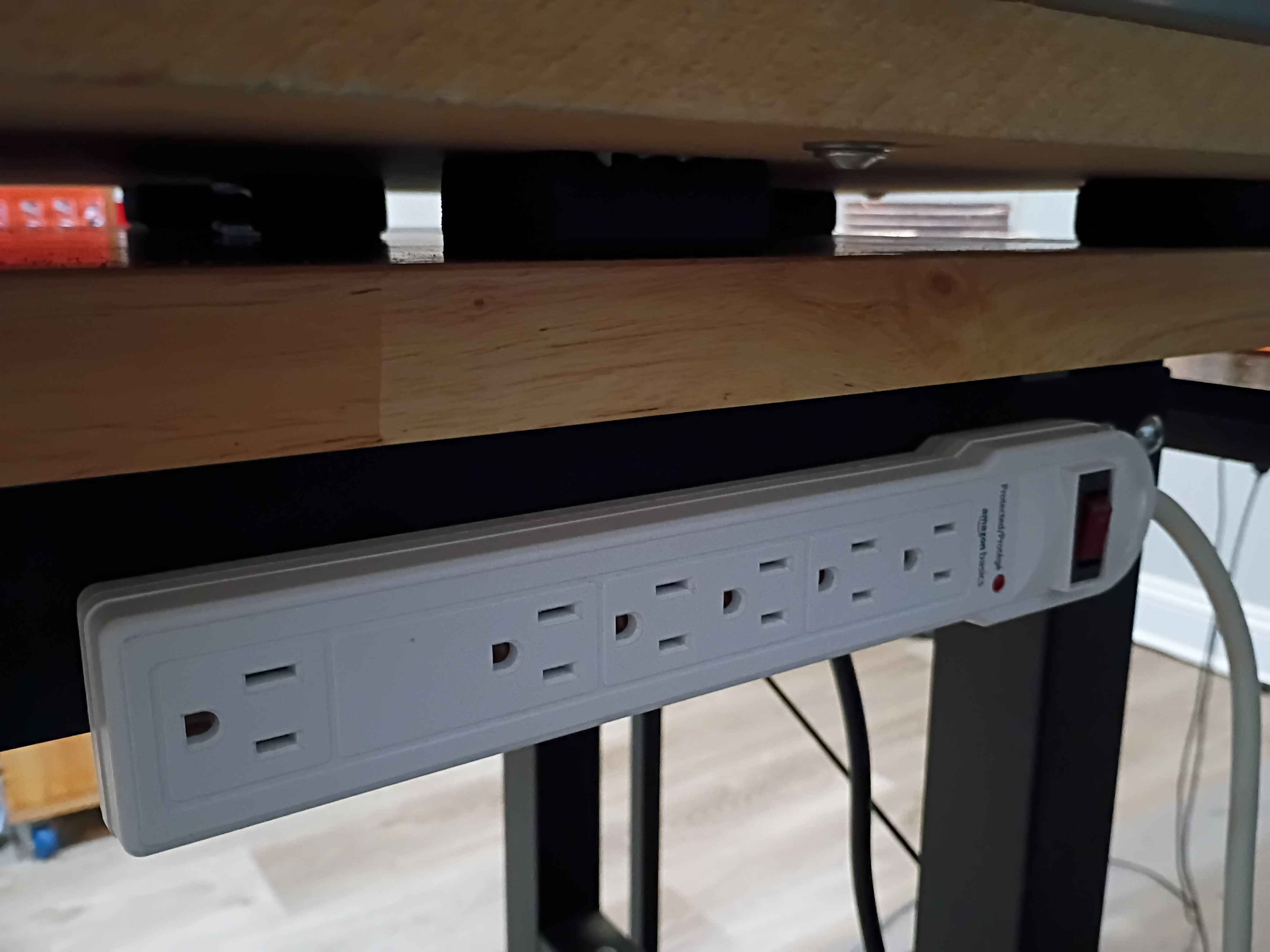
Affixed lights to the top panel, soldered their connection to the control box, and attached the entire top panel to the rest of the frame assembly. Drilled and bolted a power strip to the side of the workbench to power all the CNC subsystems, including the panel lights and ventilation. Did a test and was quite impressed with the lighting. There are no shadows. I wrapped the LED strips in loops at the right angles to avoid soldering, which worked well. 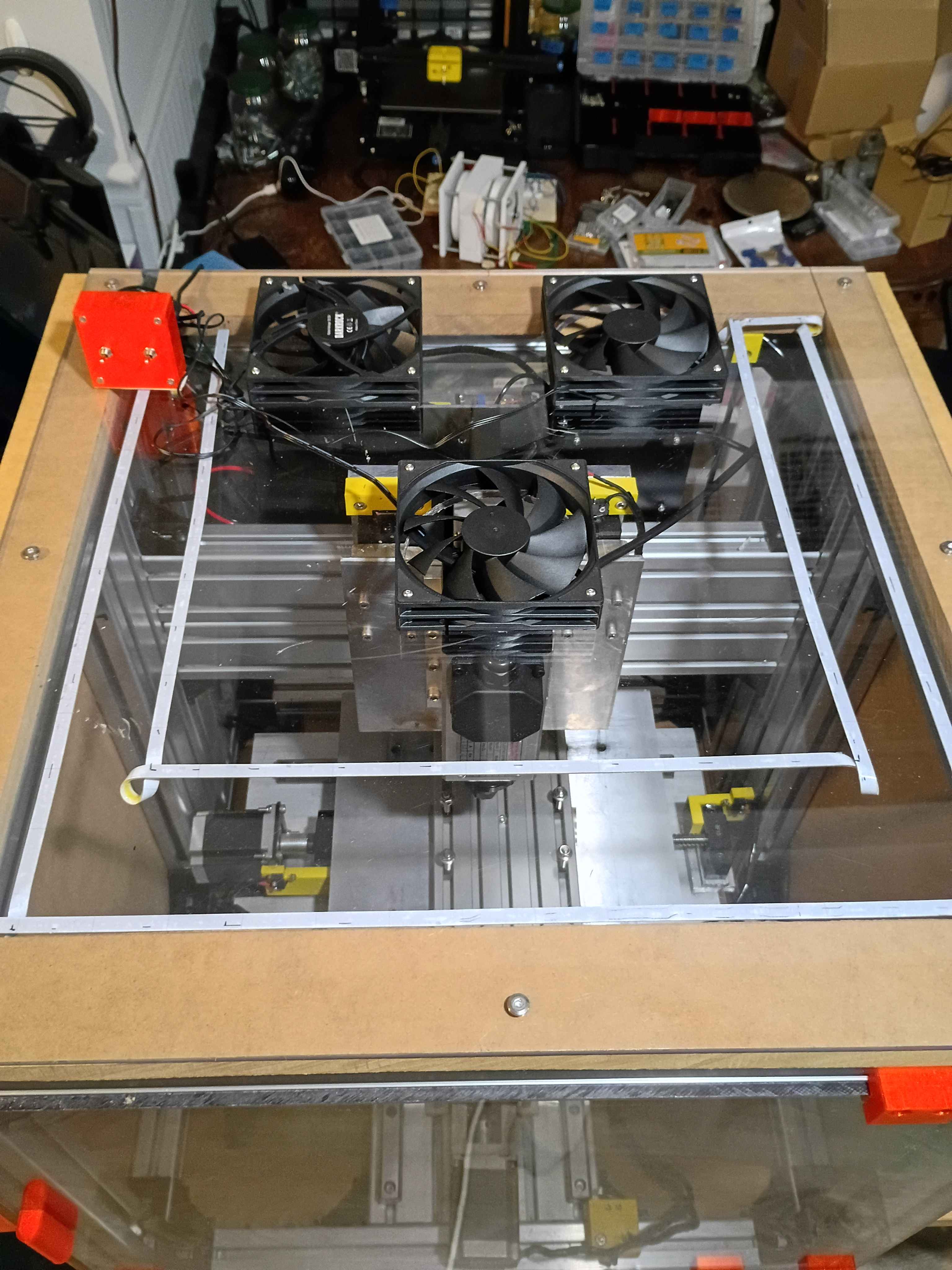
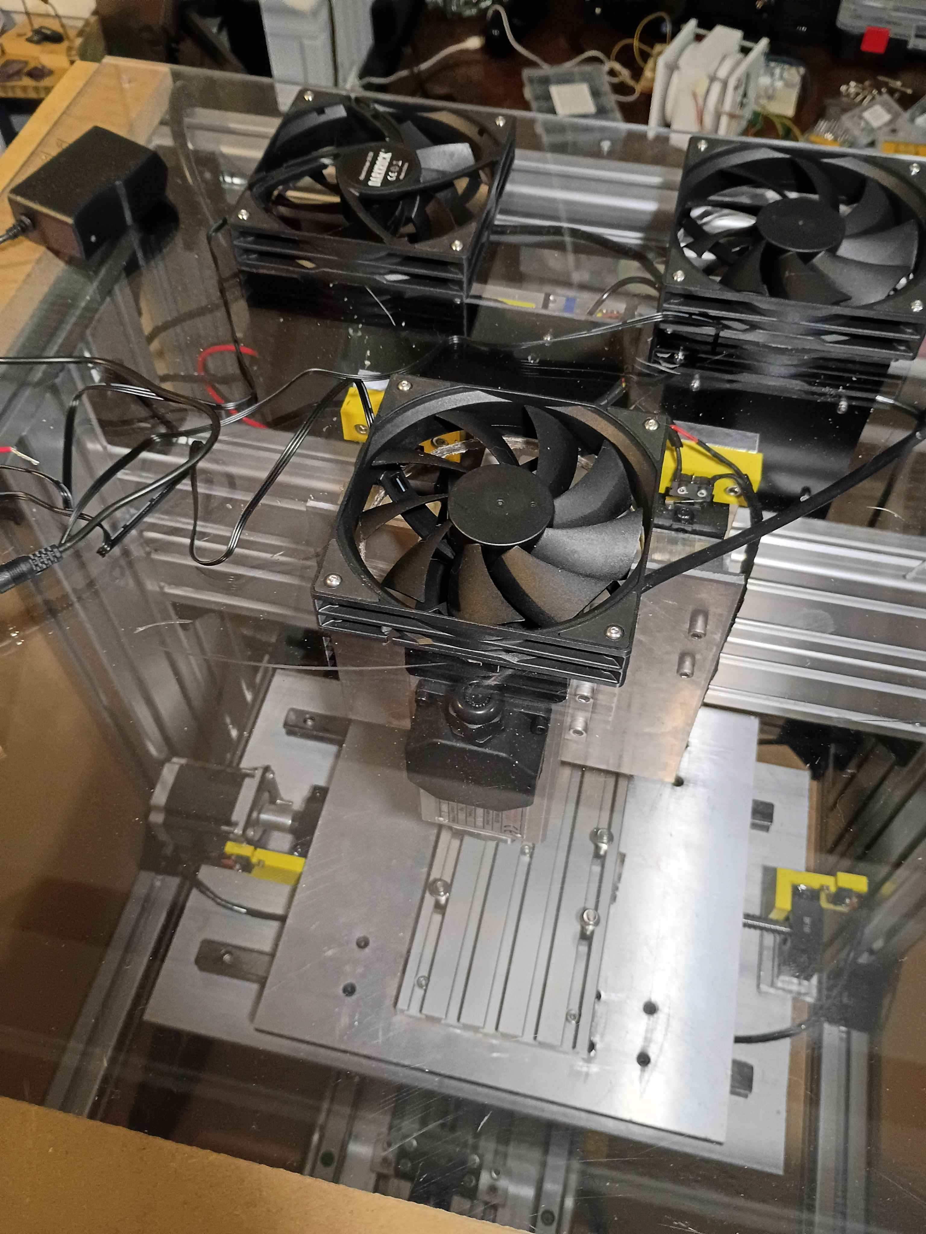
Cut 3x ventilation holes in top panel using hole saw (very hard, I blame the saw). Installed the 3x vent fans with ME screws and tested them. 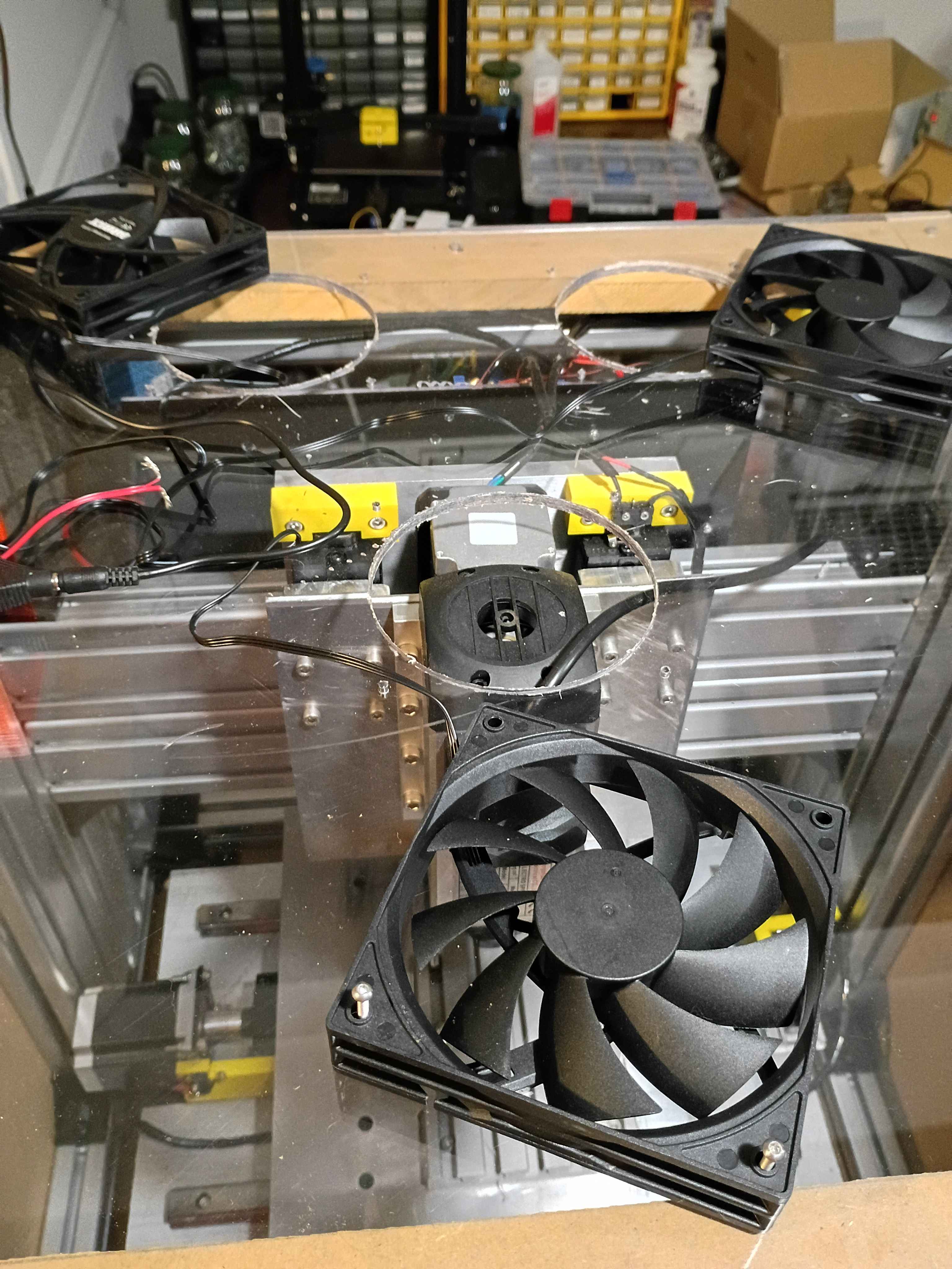
Laid out and drilled holes into upper enclosure panel and MDF spacers. Cut slots for the cables to leave the enclosure. Need a 4.5" hole saw to cut the ventilation holes before I can install everything. 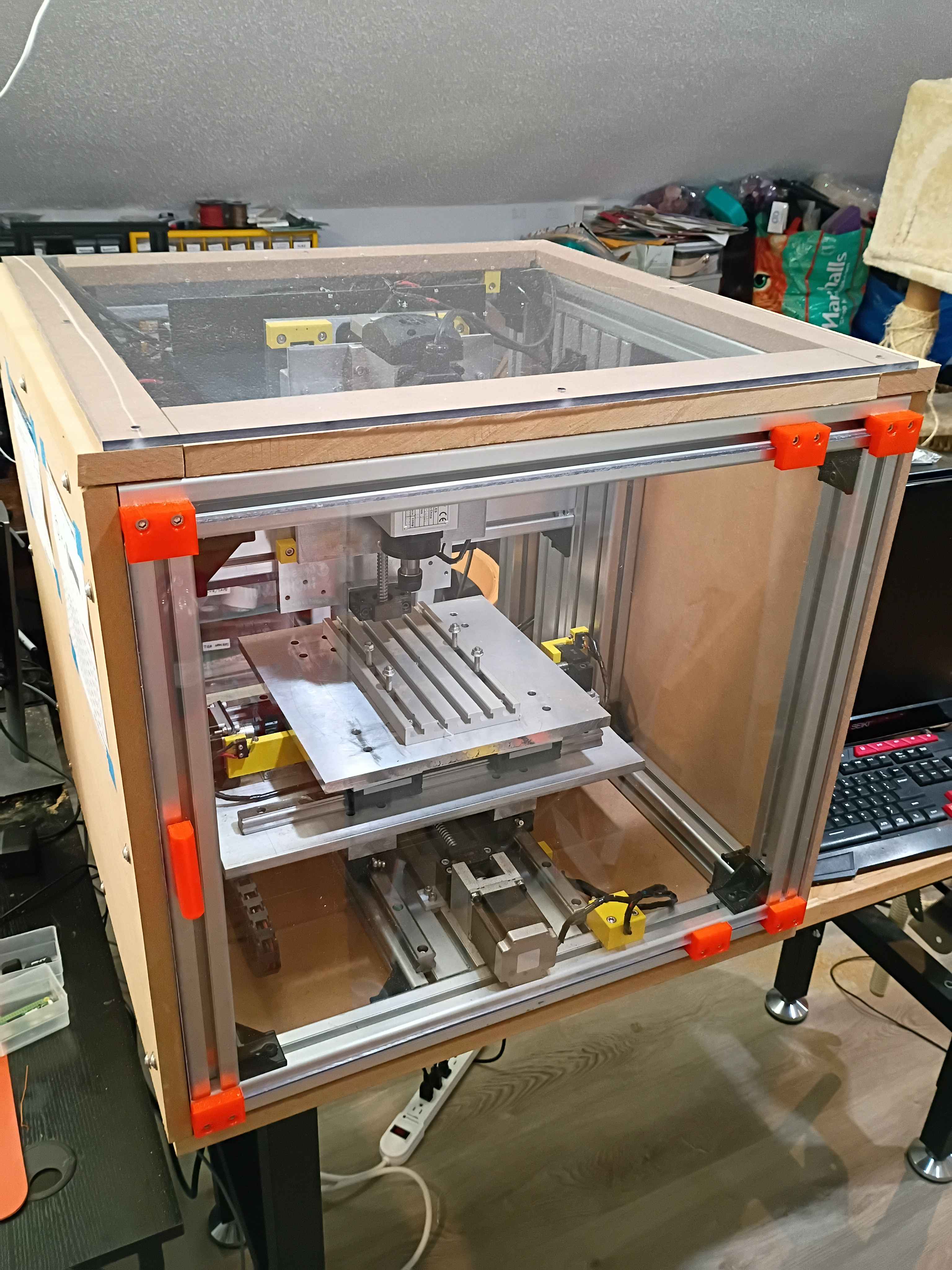
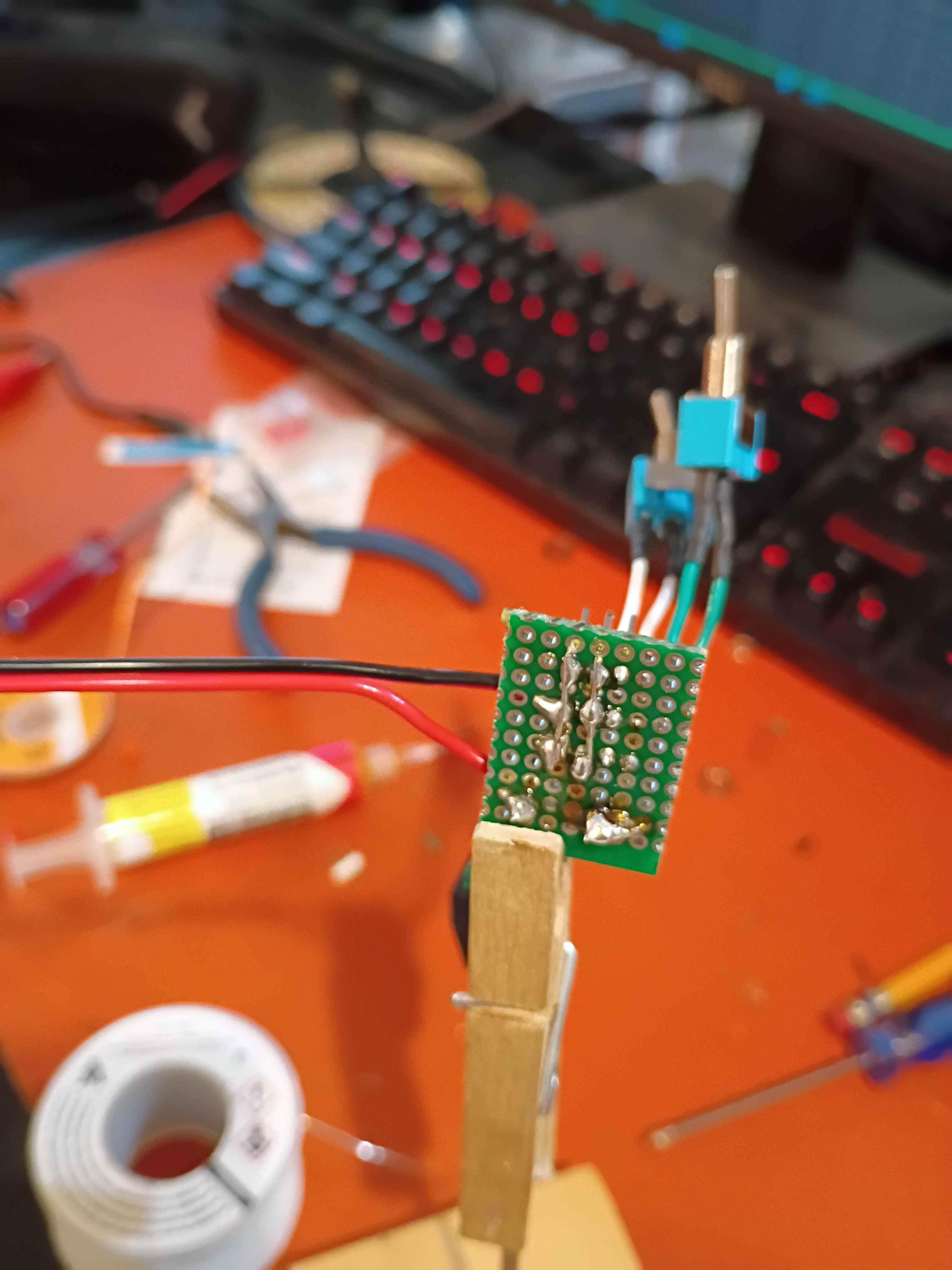
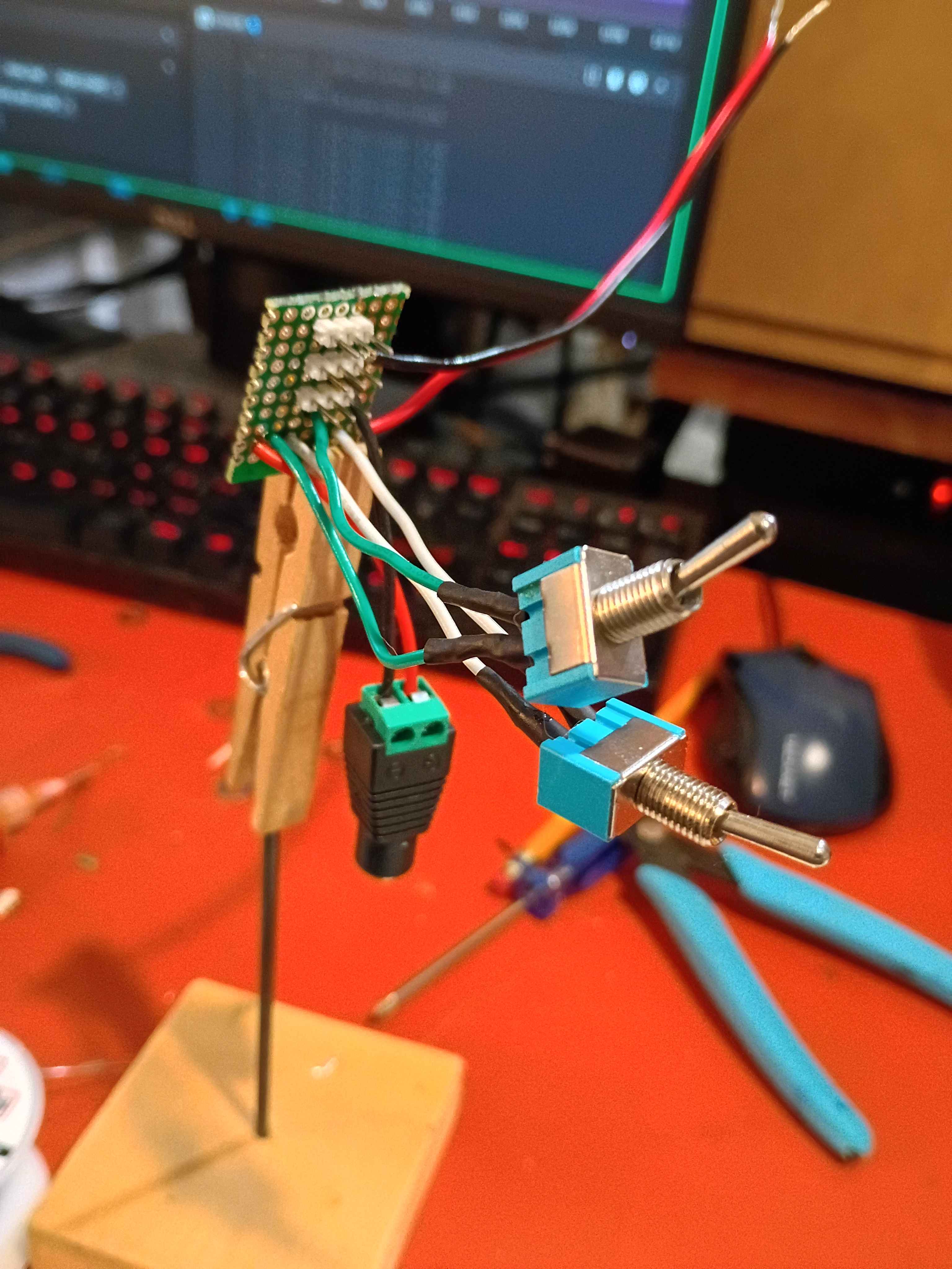
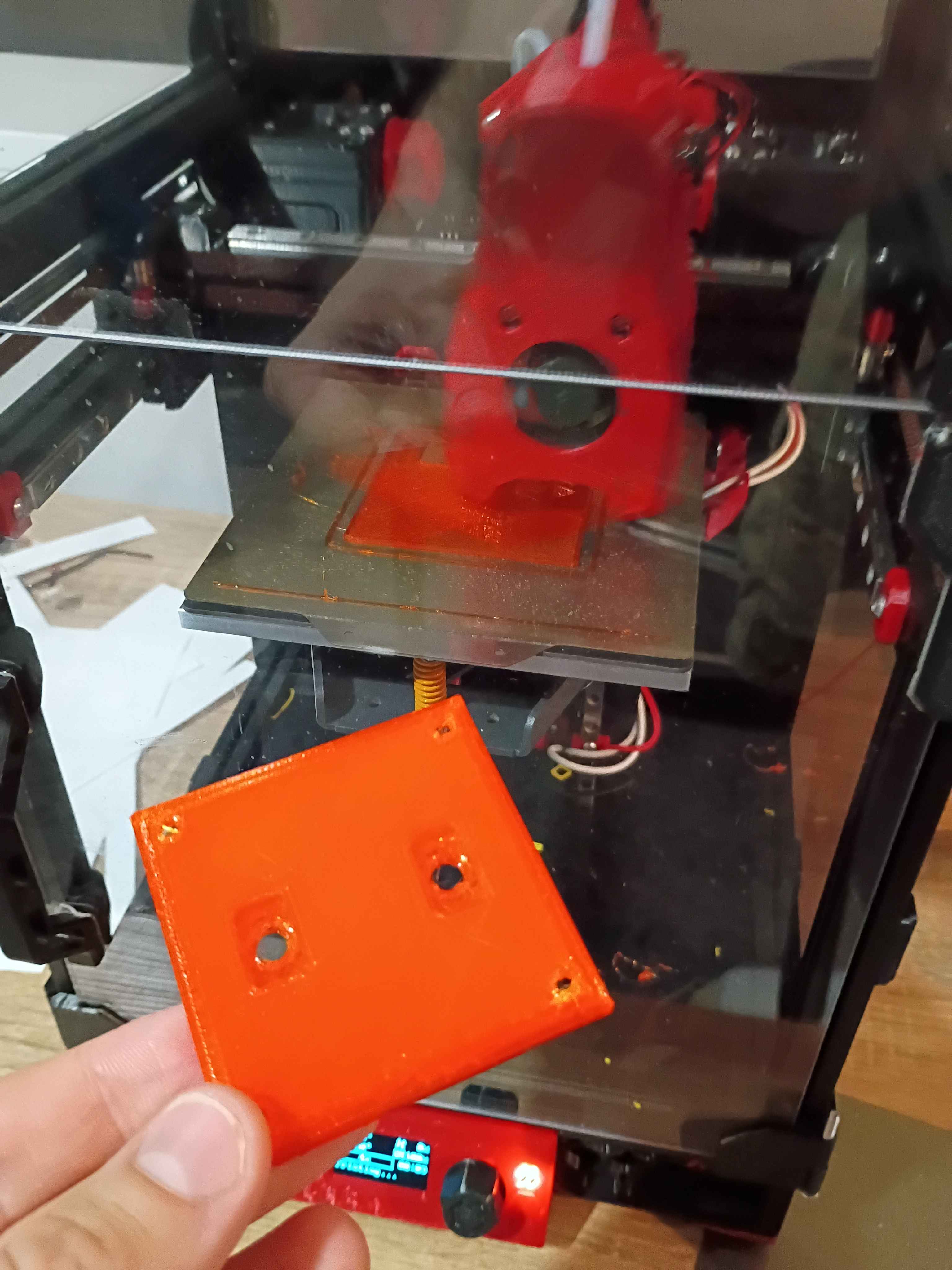
Began working on the circuitry and control box for the lighting and ventilation. Soldered up the circuit. Designed 00001-020 and -021 control box parts and began printing. One will print overnight. 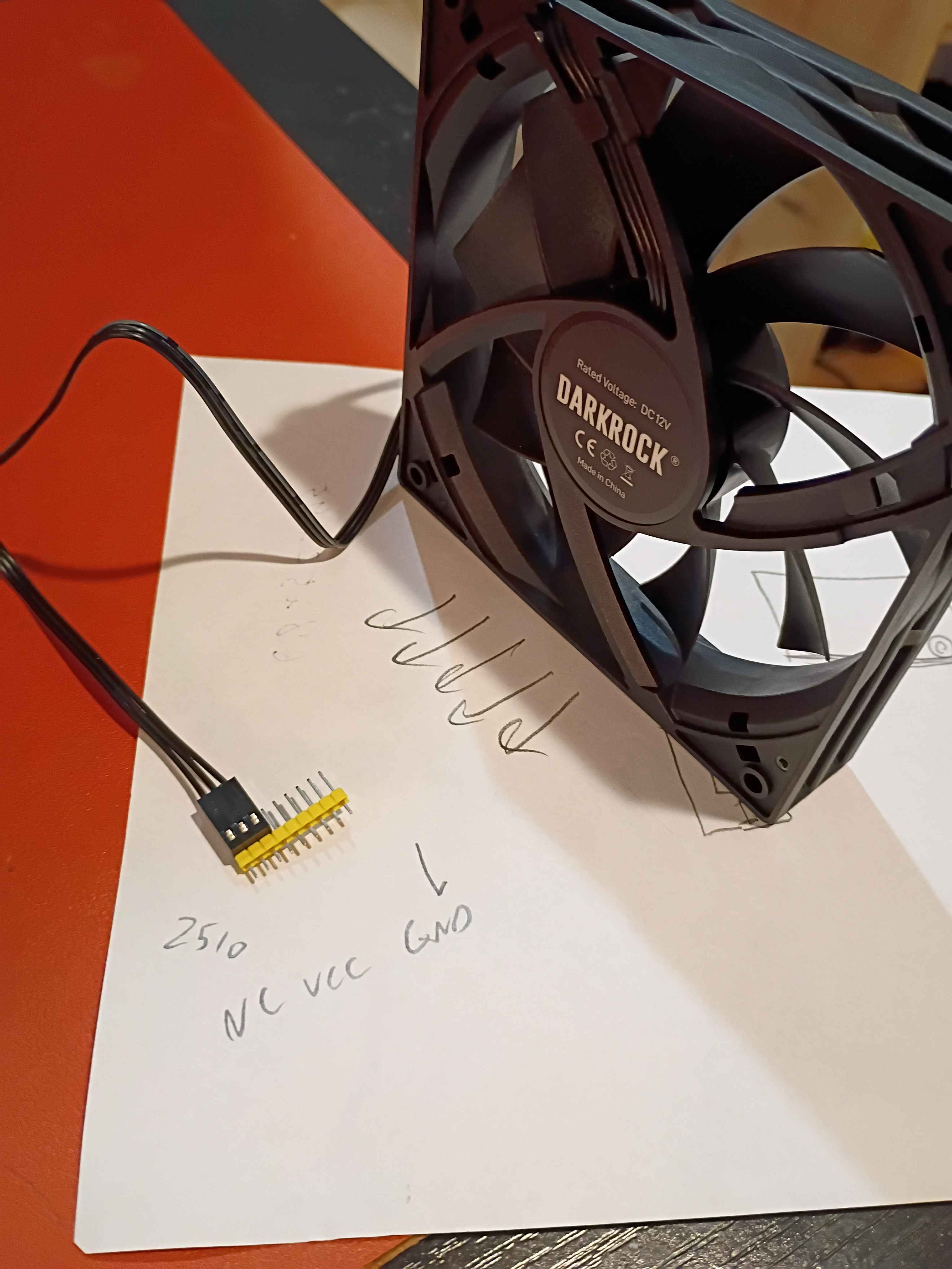
Added chamfers to the handle side of the front sliding door and also sanded the other sharp edges smooth for safety. That really helped the door slide in a lot more easily. Also cut 4 strips of 3/4" MDF to raise up the eventual top polycarbonate panel enough to clear the top of the spindle air intake in the highest z-axis position. 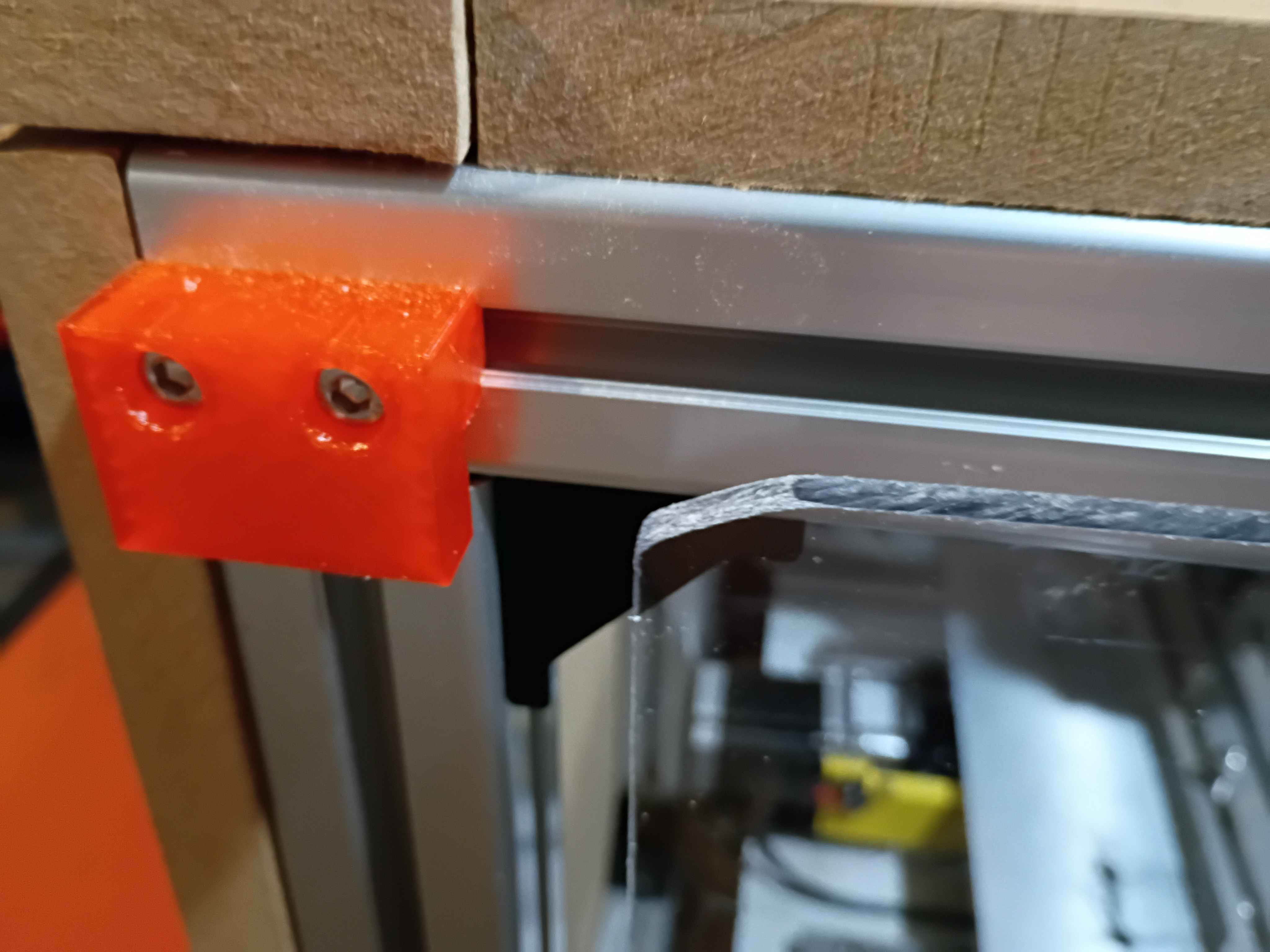
Designed and printed 00001-019 handle for front panel. Did not need any support material for the small overhangs. Melted M3x4x5 heat set inserts into the back. Cut the front polycarbonate panel to size, and drilled and countersunk holes for the M3x12 flat head screws to sit flush. Installed the sliding front panel door using 6x 00001-018 brackets, with the middle two biased toward the side opposite the handle, to keep supporting the panel while it is open. It is a bit dangerous on the free end when the door is open, and it's kind of a pain on the handle end to line it up when closing the door, so I might add a chamfer to all 4 corners. Also cleaned up some of the electronics yesterday, but forgot to record that. 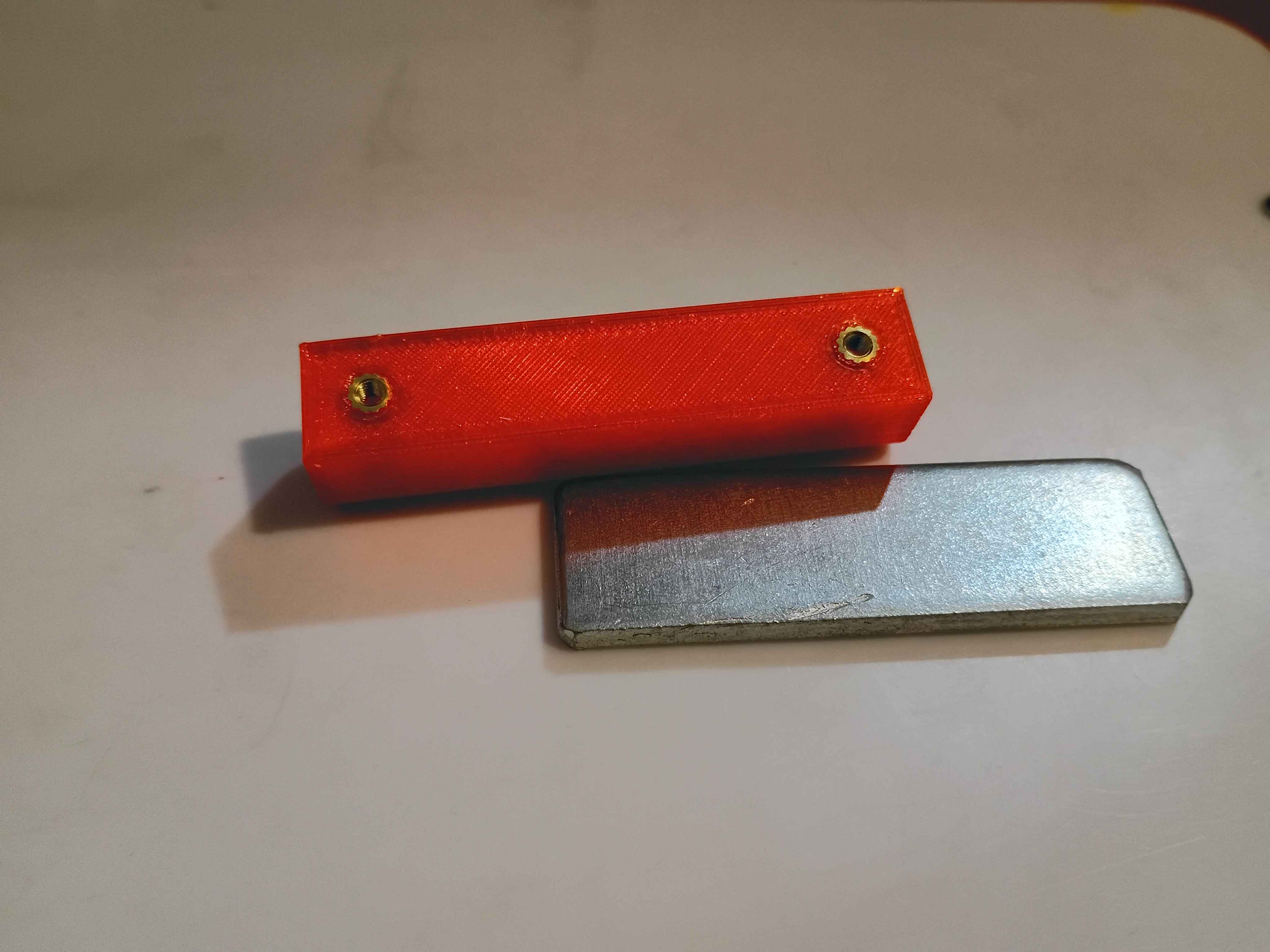
First chips on CNC. Cut 10mm cube into MDF at 300 Hz or 18000 RPM using 3.00mm endmill. Something about the depth seems off, but the x/y are spot on. Need to think a bit about how the x/y directions are oriented. See video. 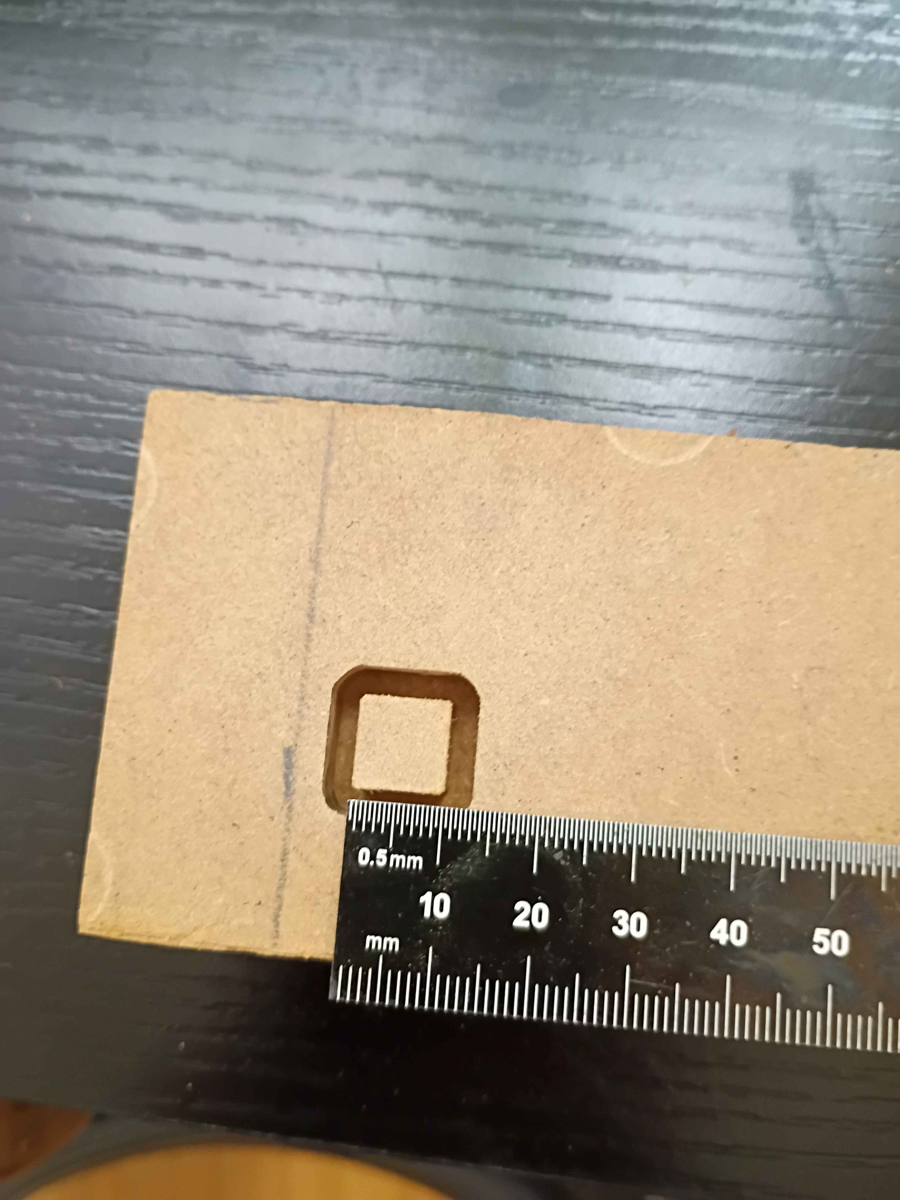
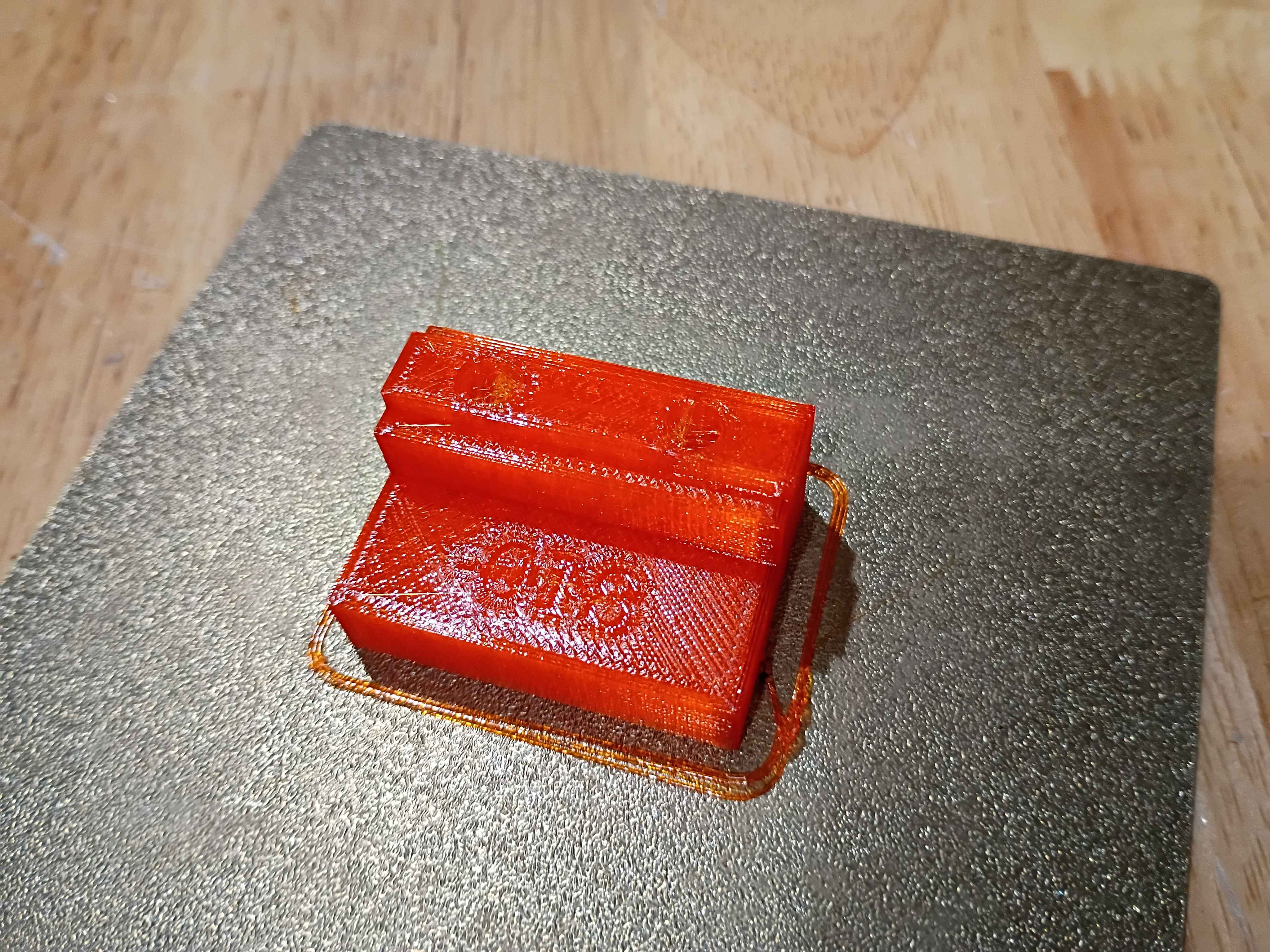
Cut polycarbonate back panel and installed it with all the necessary brackets, including some old repurposed ones. Routed the wires in the back area using some 00001-017 brackets. Cut the side MDF panels to size with a flush cut saw. Designed and printed a first 00001-018 bracket for the front sliding door, which is an exact copy of the 00001-016 with an additional .5mm of room for the polycarbonate panel to slide, and printed in translucent orange PCTG instead of ASA. It also has the part number embossed in one of the non-visible surfaces for easy identification. 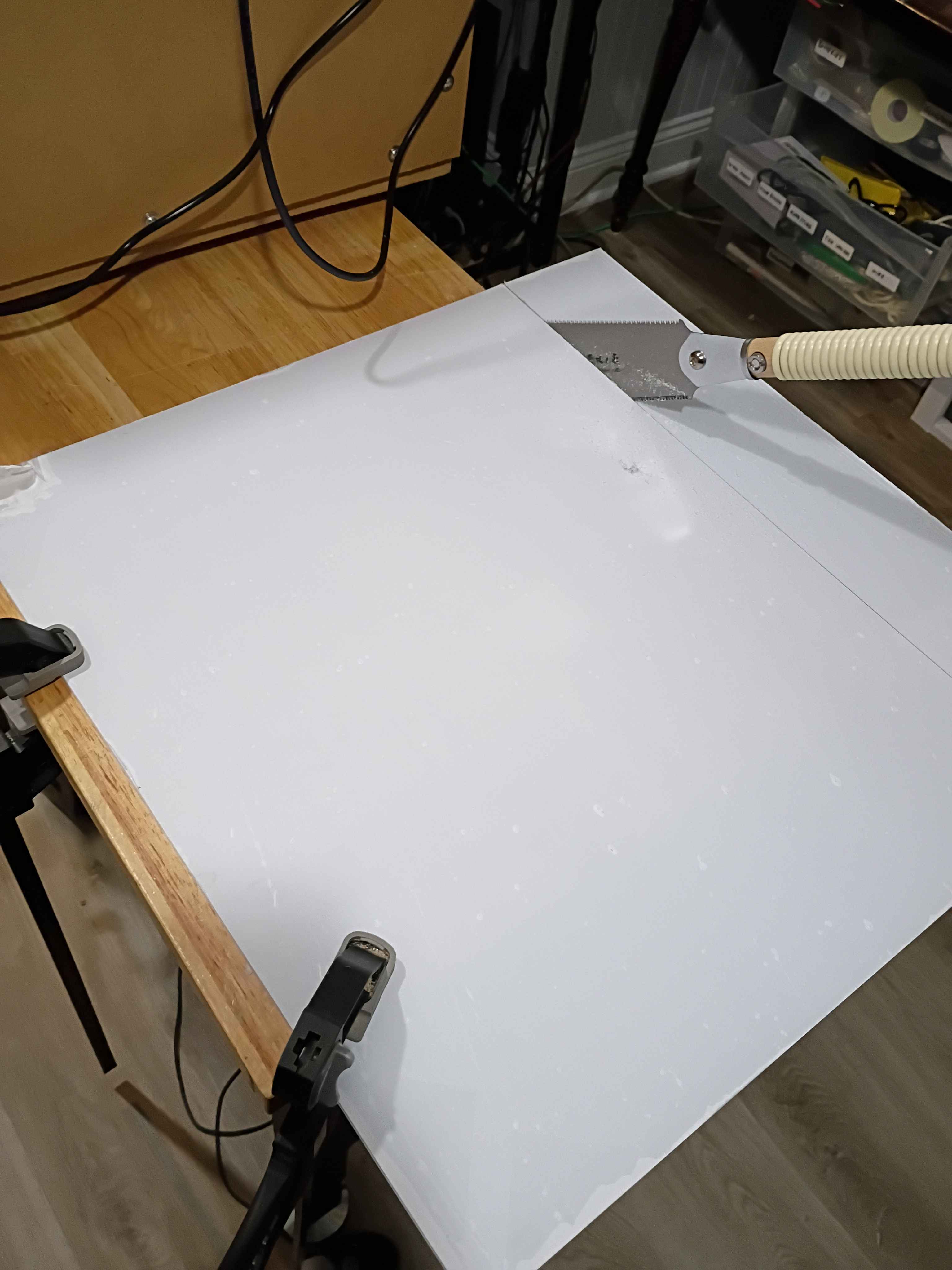
Soldered, rerouted, and rewrapped some of the wires for the electrical panel. Also printed out some prototype brackets for wire routing. 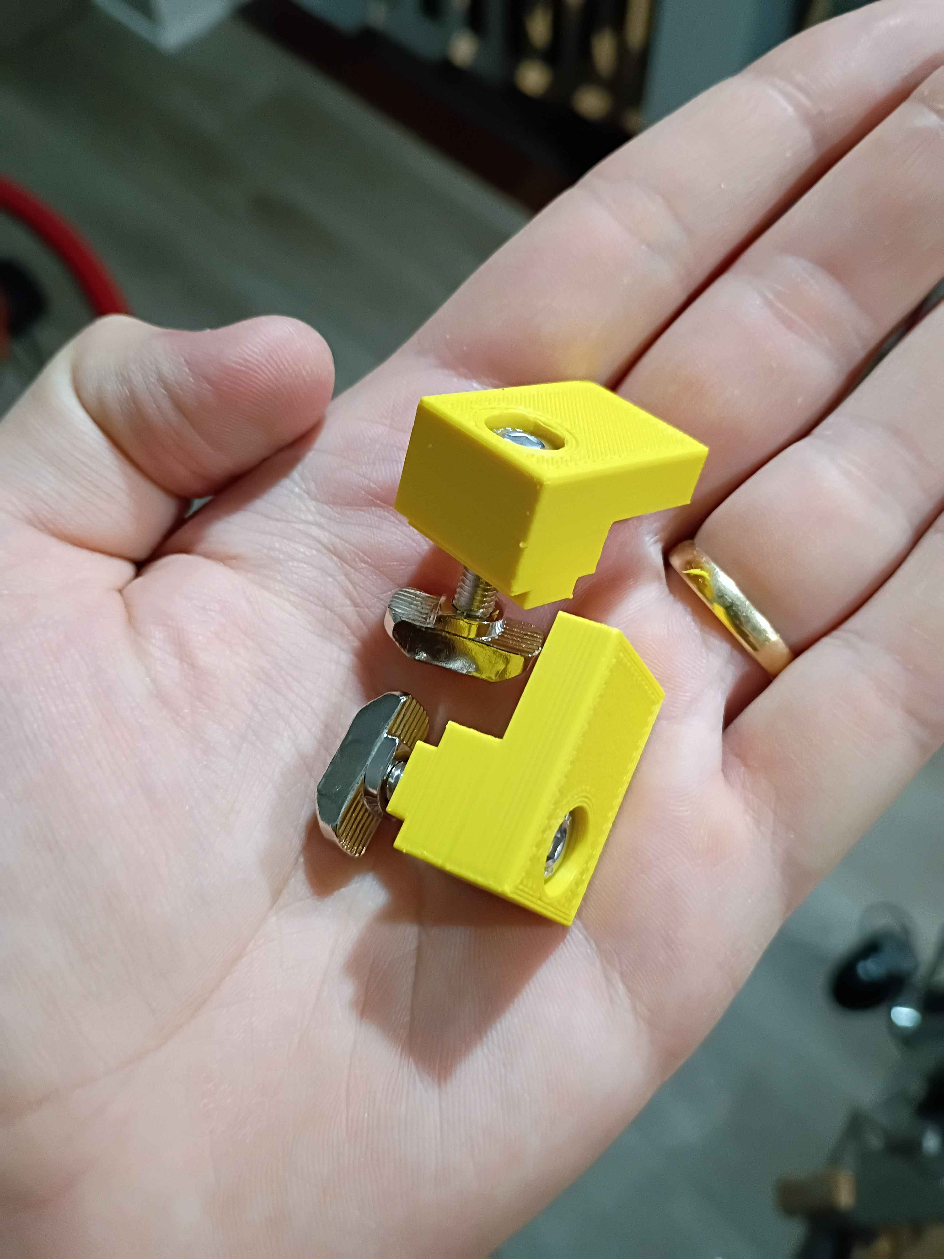
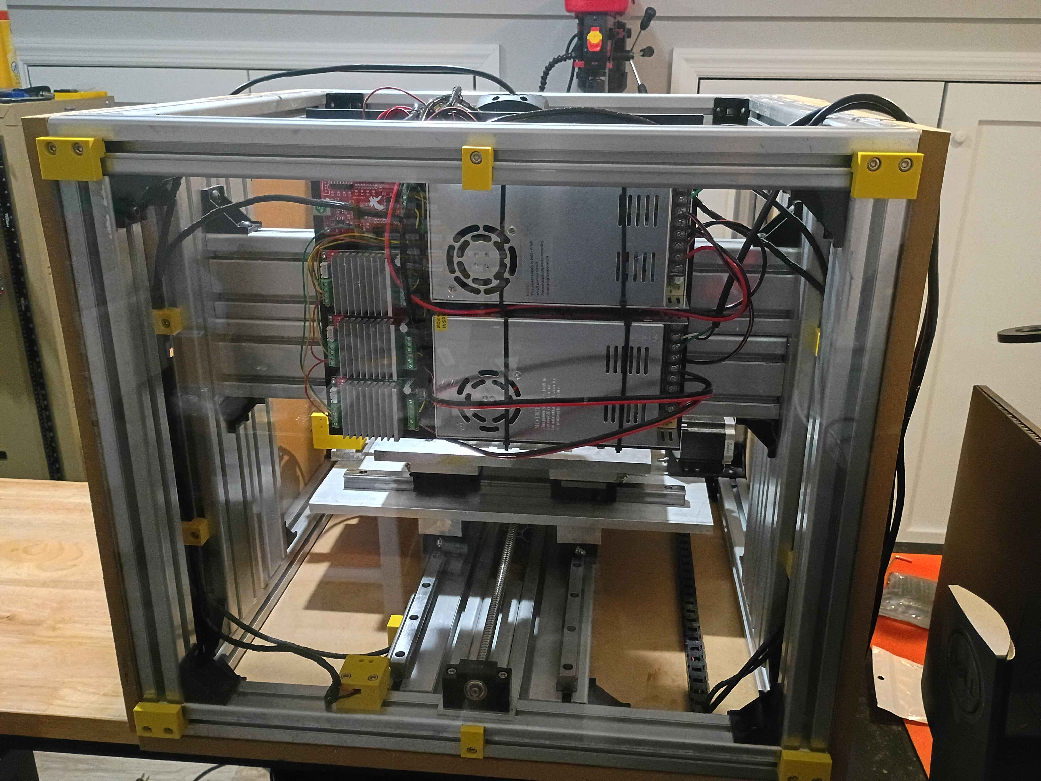
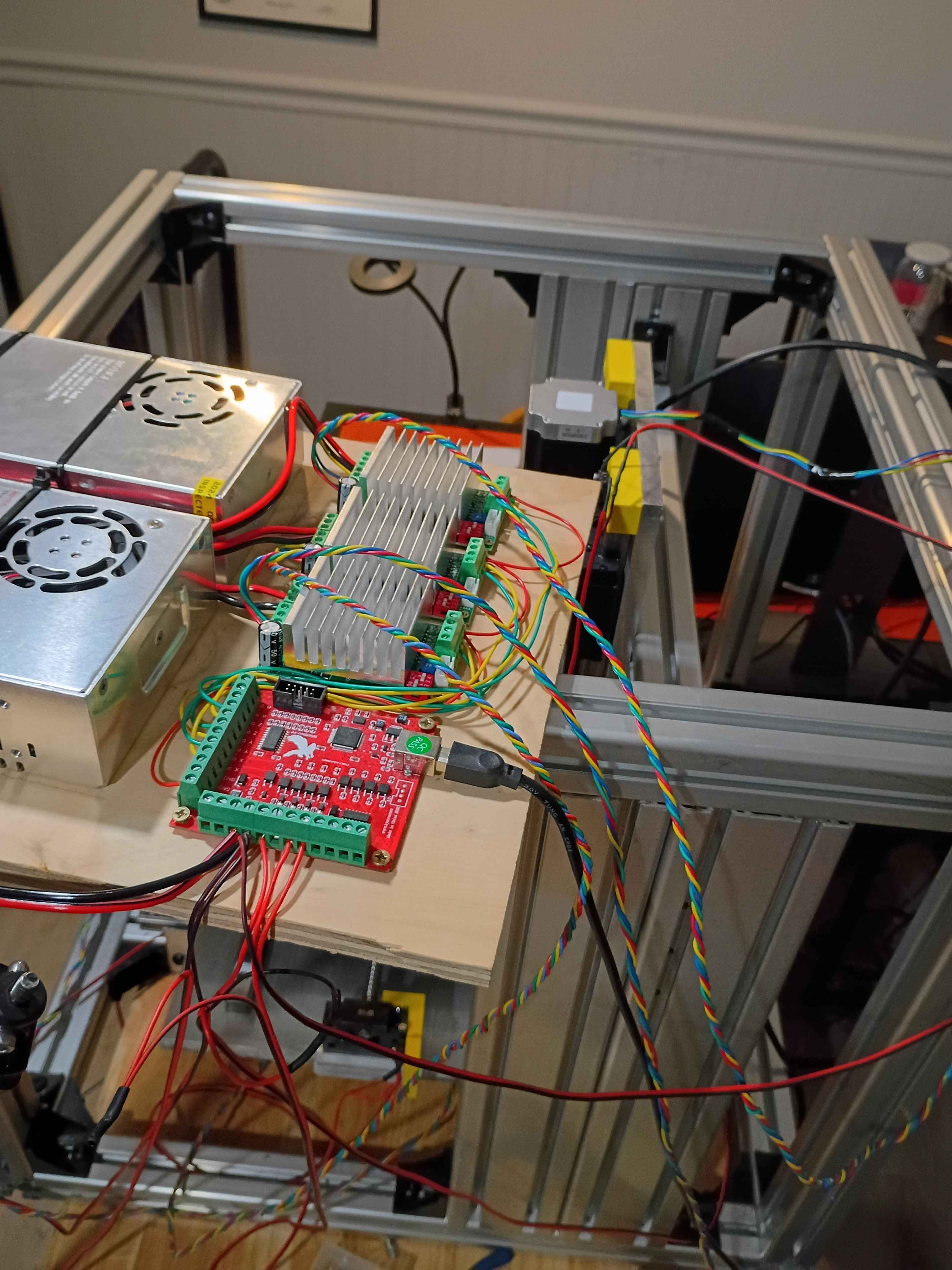
Though it took an insane effort, got the entire electrical system mounted up and rewired, after trimming the lead wires shorter. Accidentally had it upside down, too. Also printed all the door slide brackets. 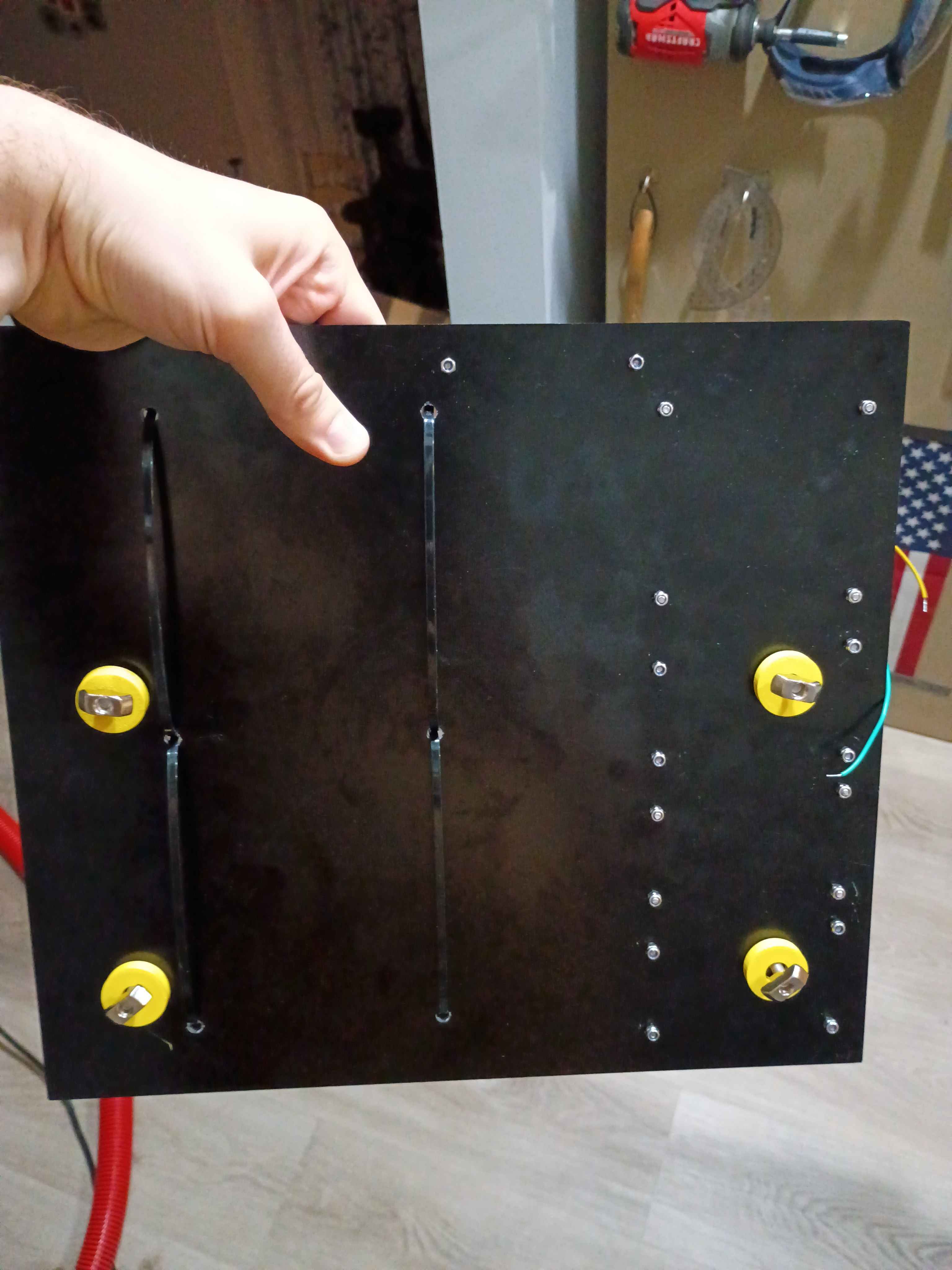
Designed and printed 00001-016 sliding door panel brackets that accept 2x M5x20 bolts to attach to 4040 T-slot nuts. It worked successfully on the first attempt. Printing 7 more over the next couple days. 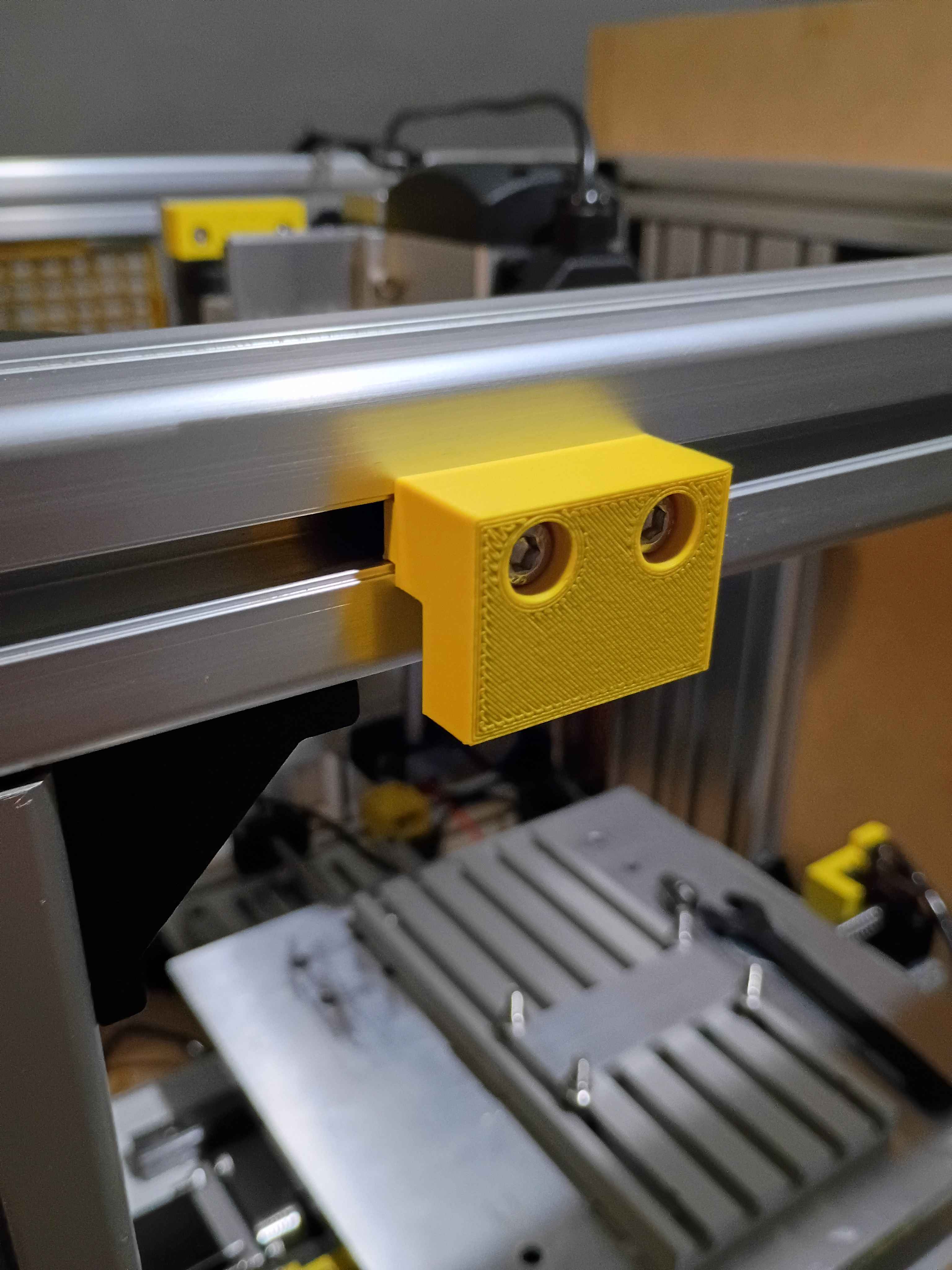
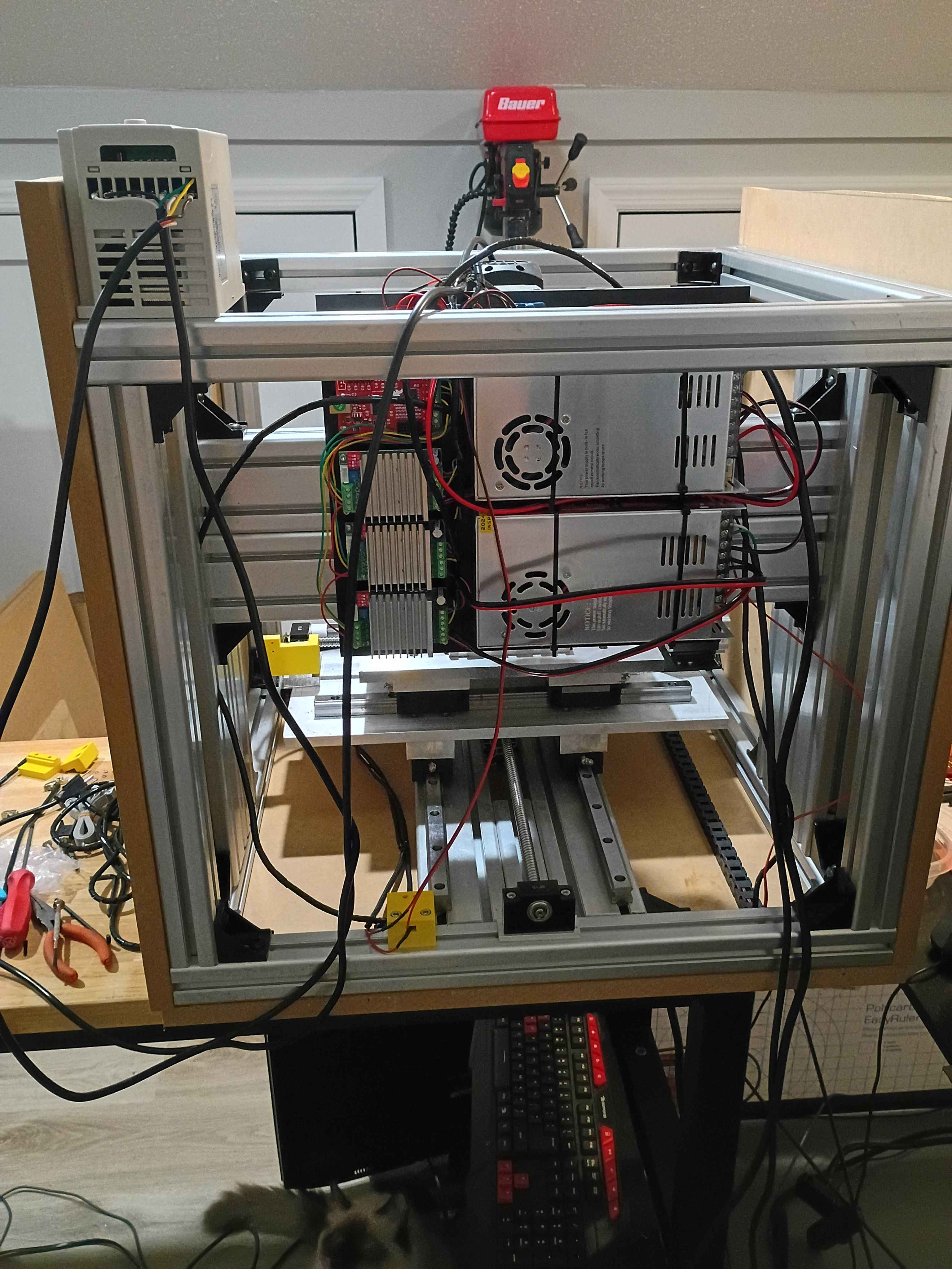
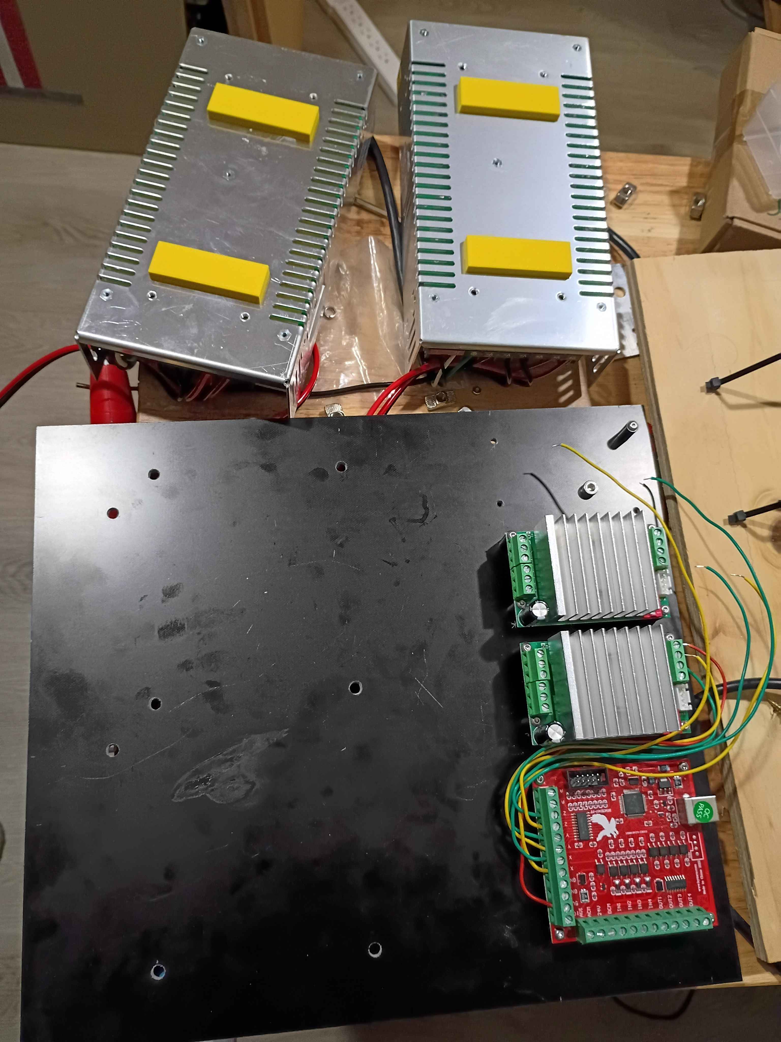
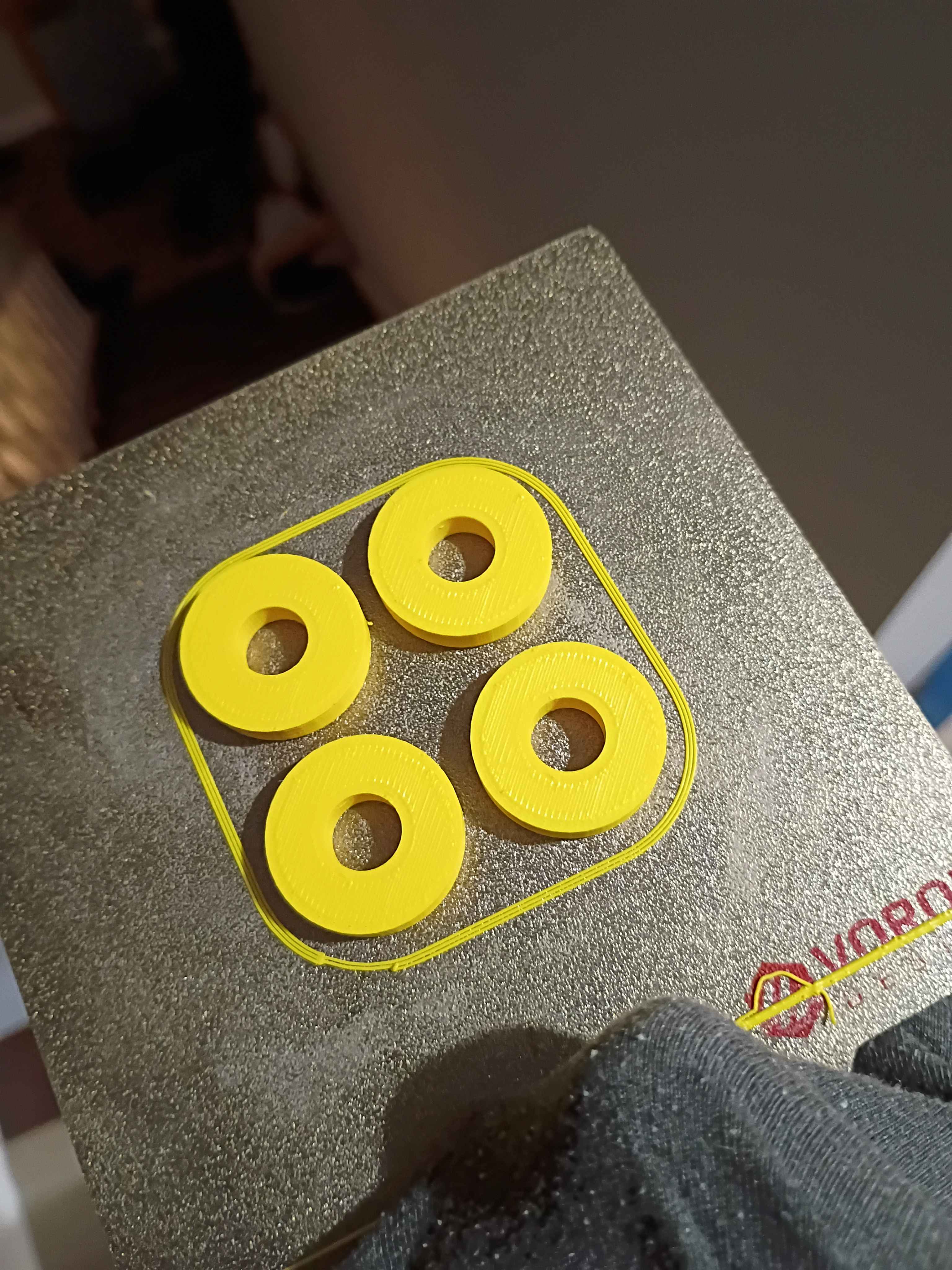
Drilled holes in G10 fiberglass electrical mount plate, began to mount up some components using spacers, realizing I will need some more M3x20 screws and a set of stubby Allen wrenches, and designed & printed some rectangular 00001-014 spacers for the inverters and some cylindrical 00001-15 spacers to mount the entire panel to the aluminum frame. While this will work, it would be better if I planned out the electrical subsystem placement to not shroud the hardware mounting the panel to the frame underneath the hardware mounting the electrical components to the panel, as that just makes things unnecessarily difficult to install. 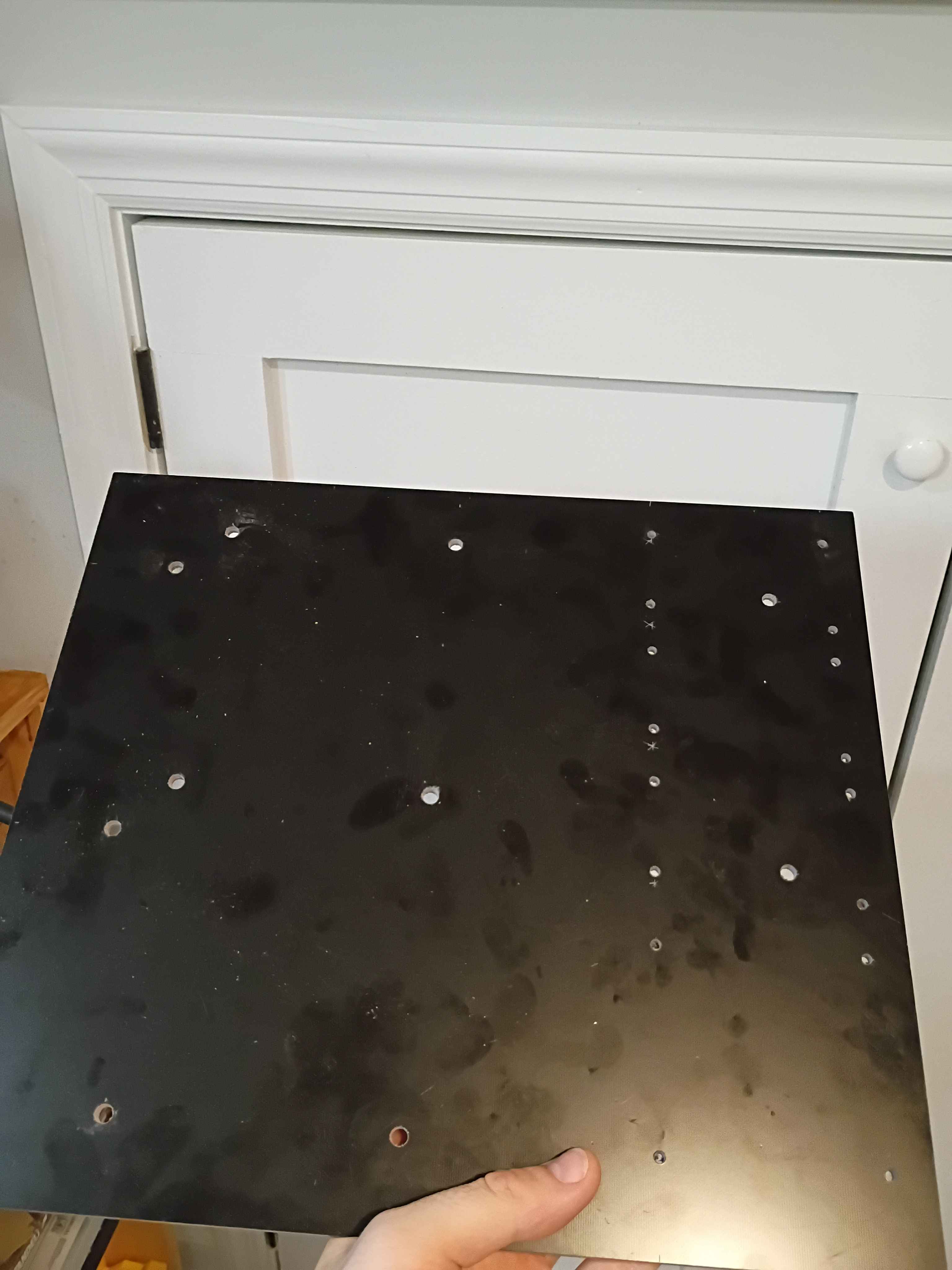
Planned out electrical panel drill pattern based on the initial plywood version, but slightly less flammable since it will be made of G10 fiberglass. Received the laminate today, but waiting on spacers. 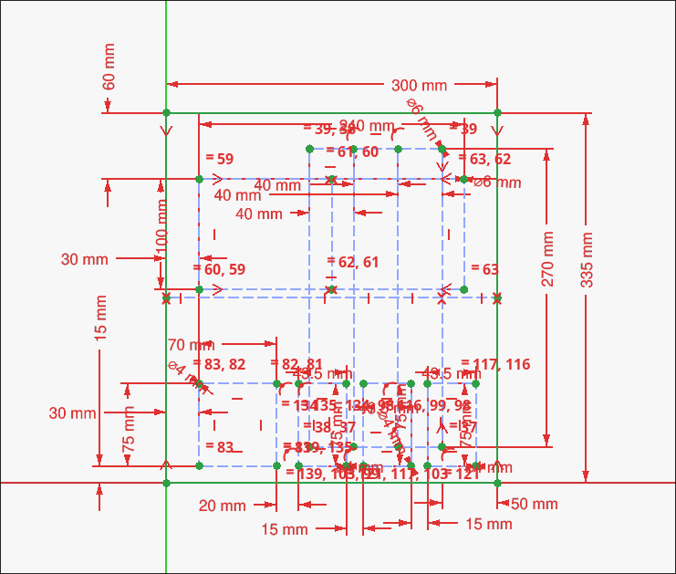
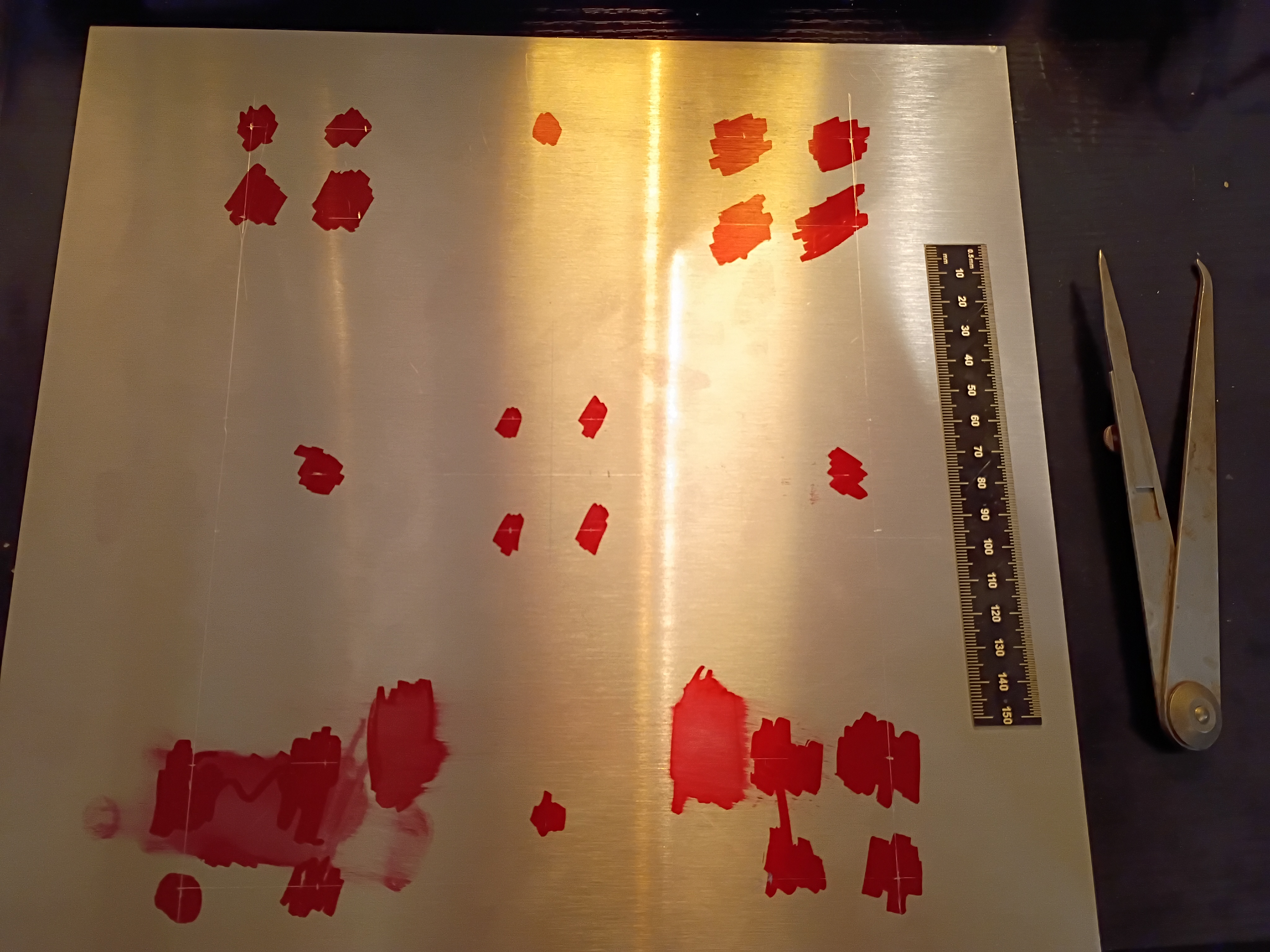
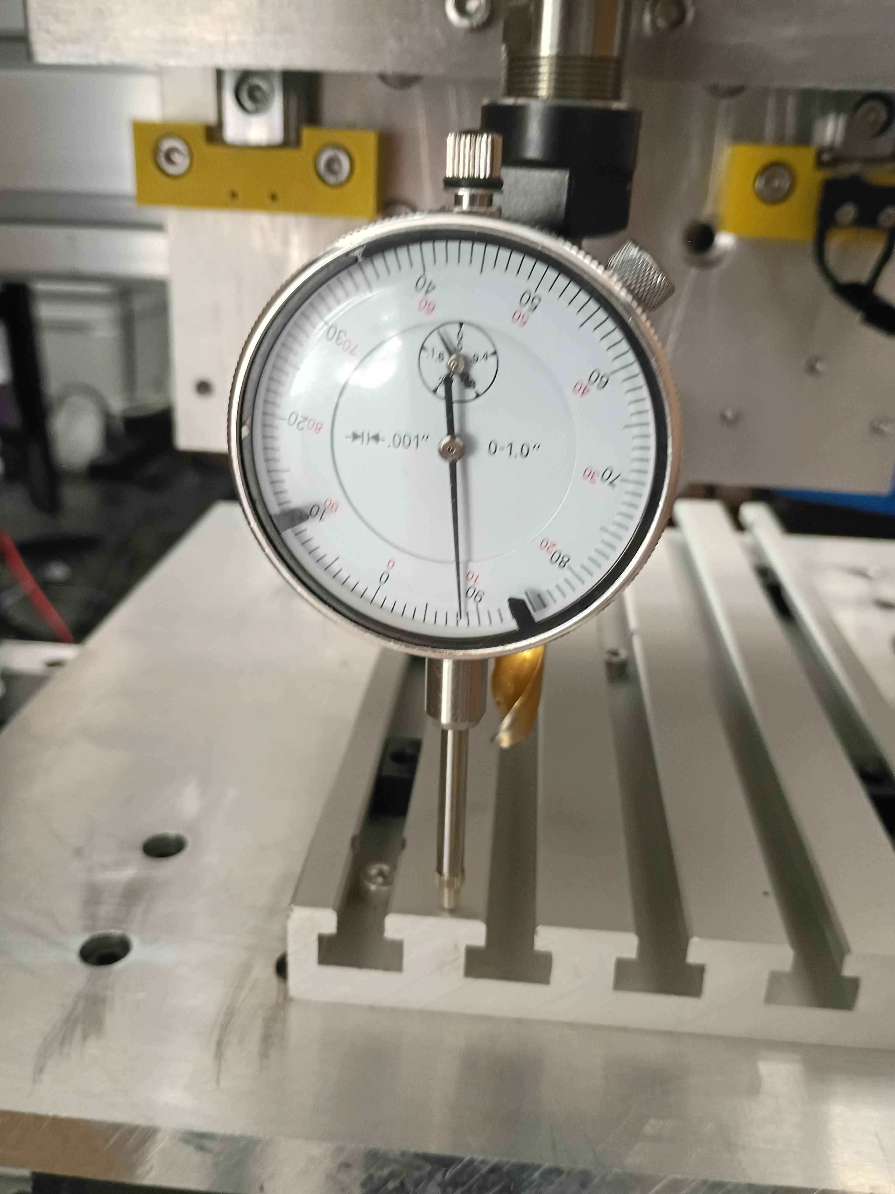
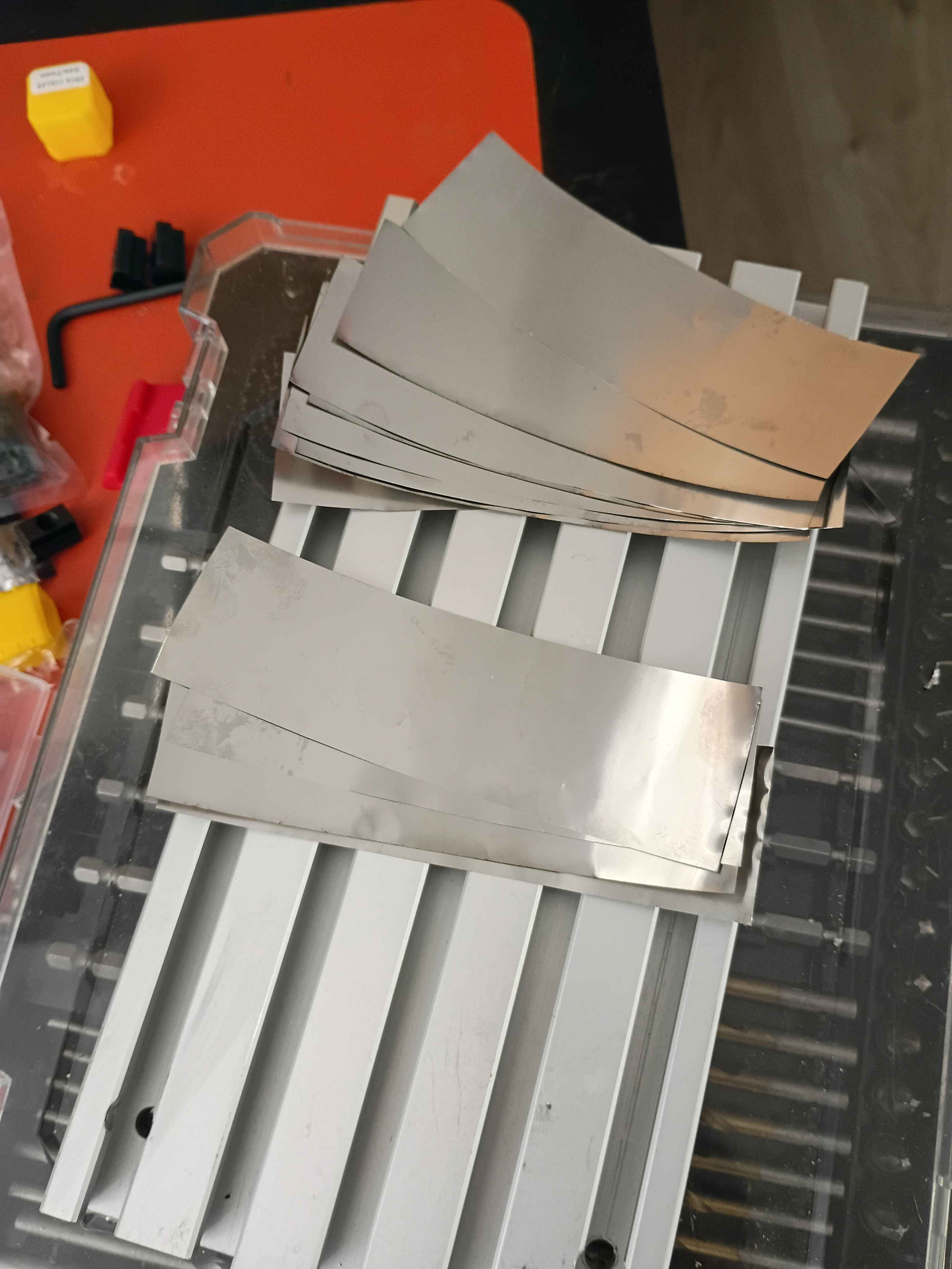
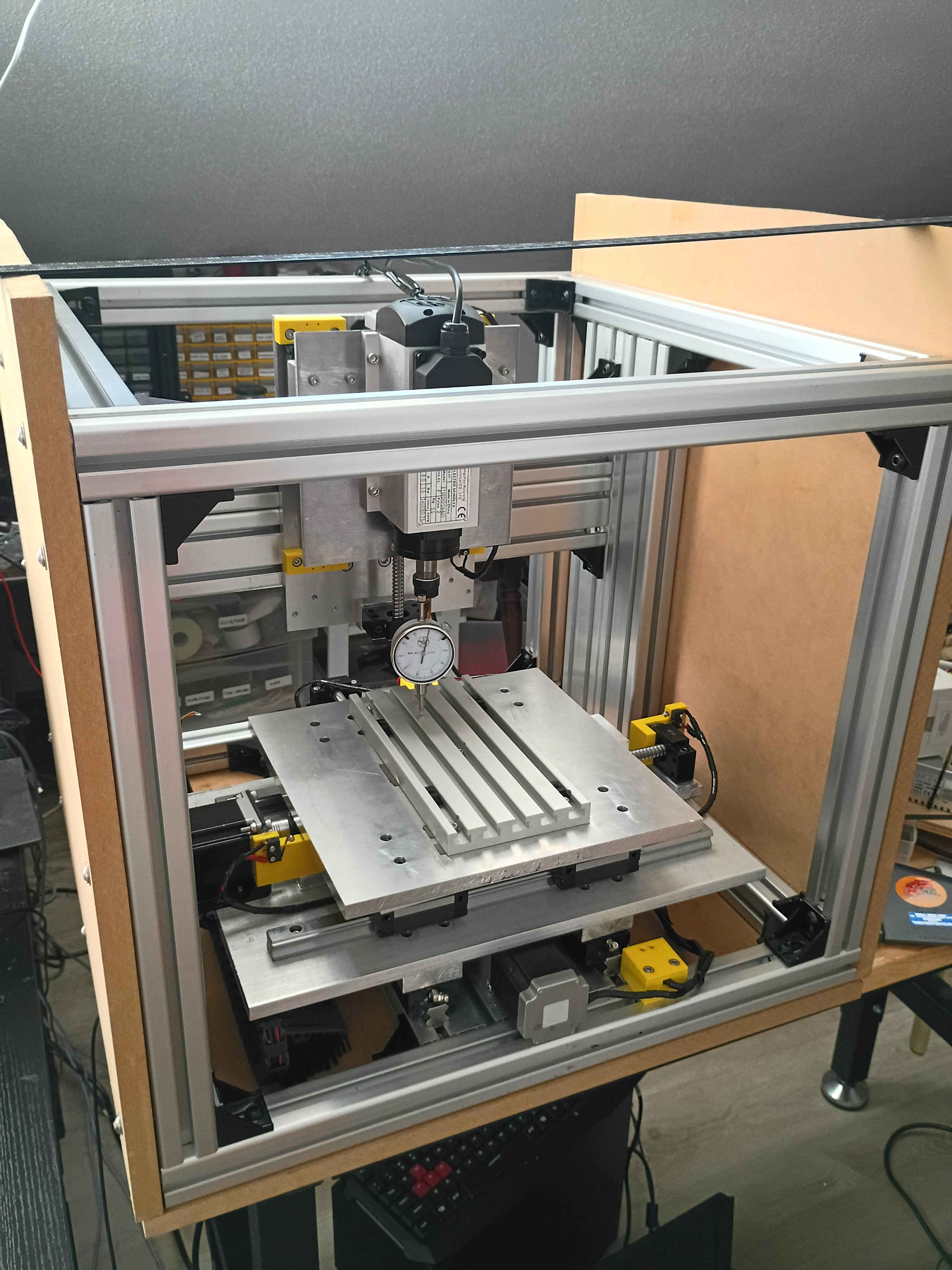
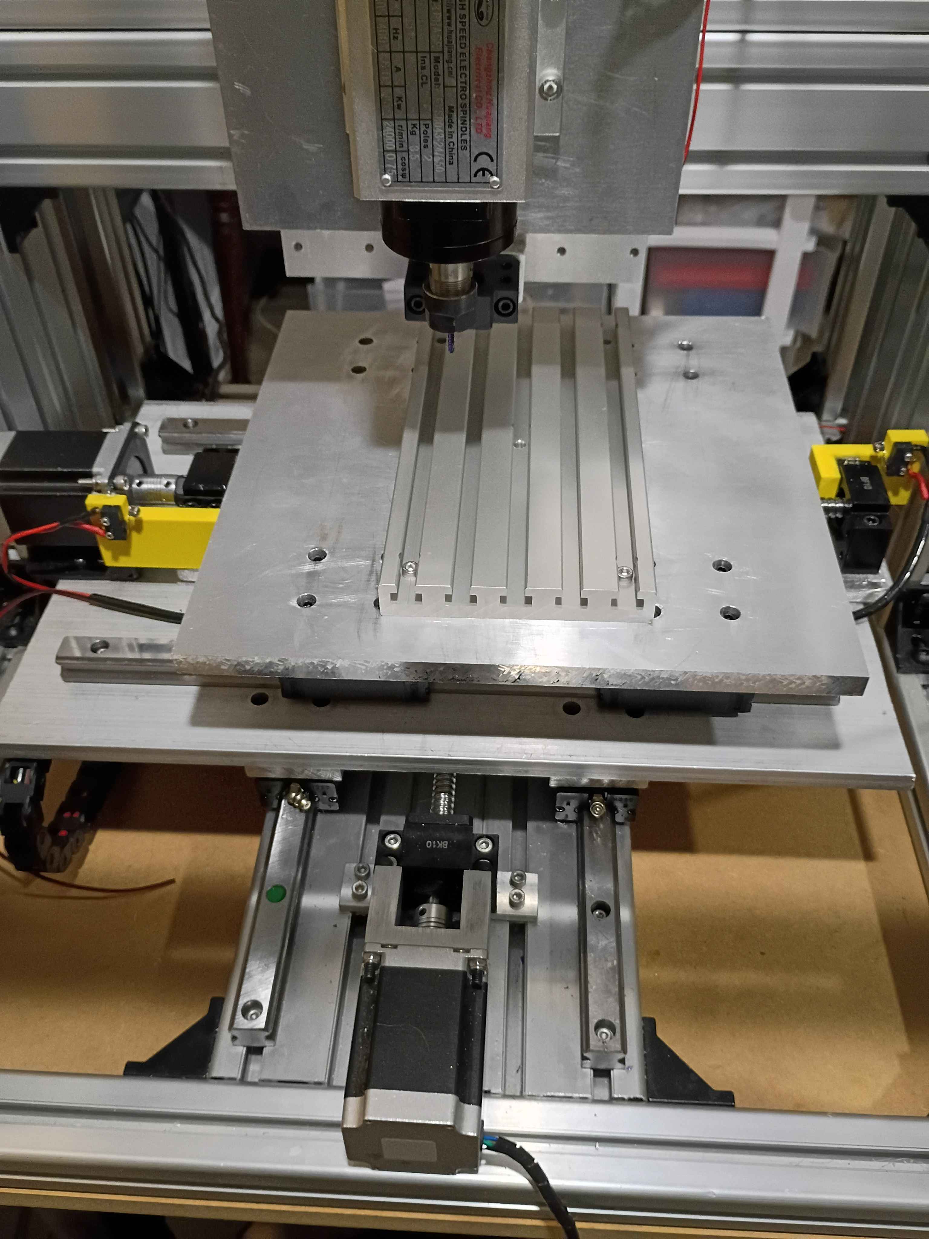
Insert dial indicator into spindle using a 10mm drill bit as an adapter. Determined that the y axis was tram within .0005" and the x axis was tram within .008" over 8 inches of travel. Cut some .001" strips of stainless steel and inserted 4x at the middle of the T-slot fixture plate and 8x at the end, reducing the tram error to less than .0005". Still need to determine if the T slots run truly parallel to the x-axis or not. 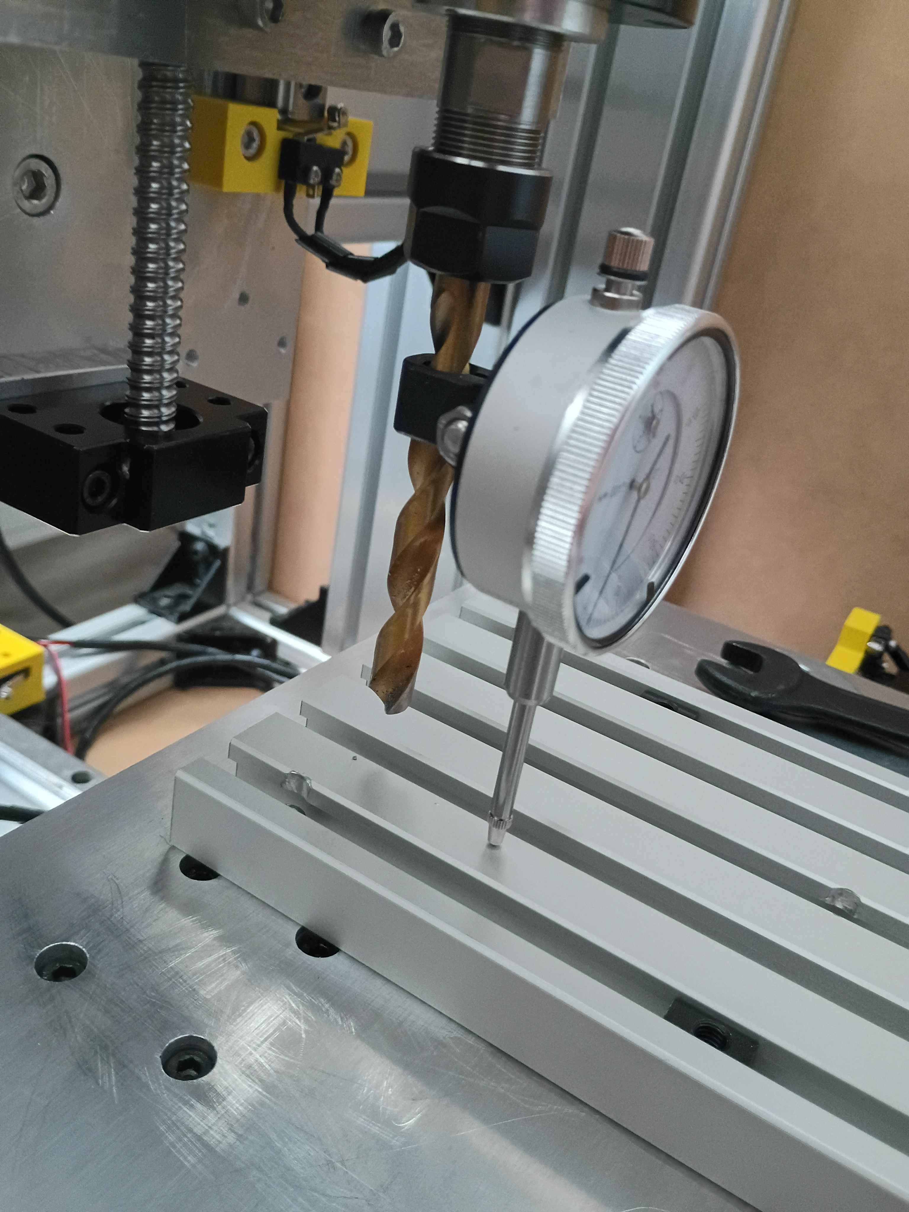
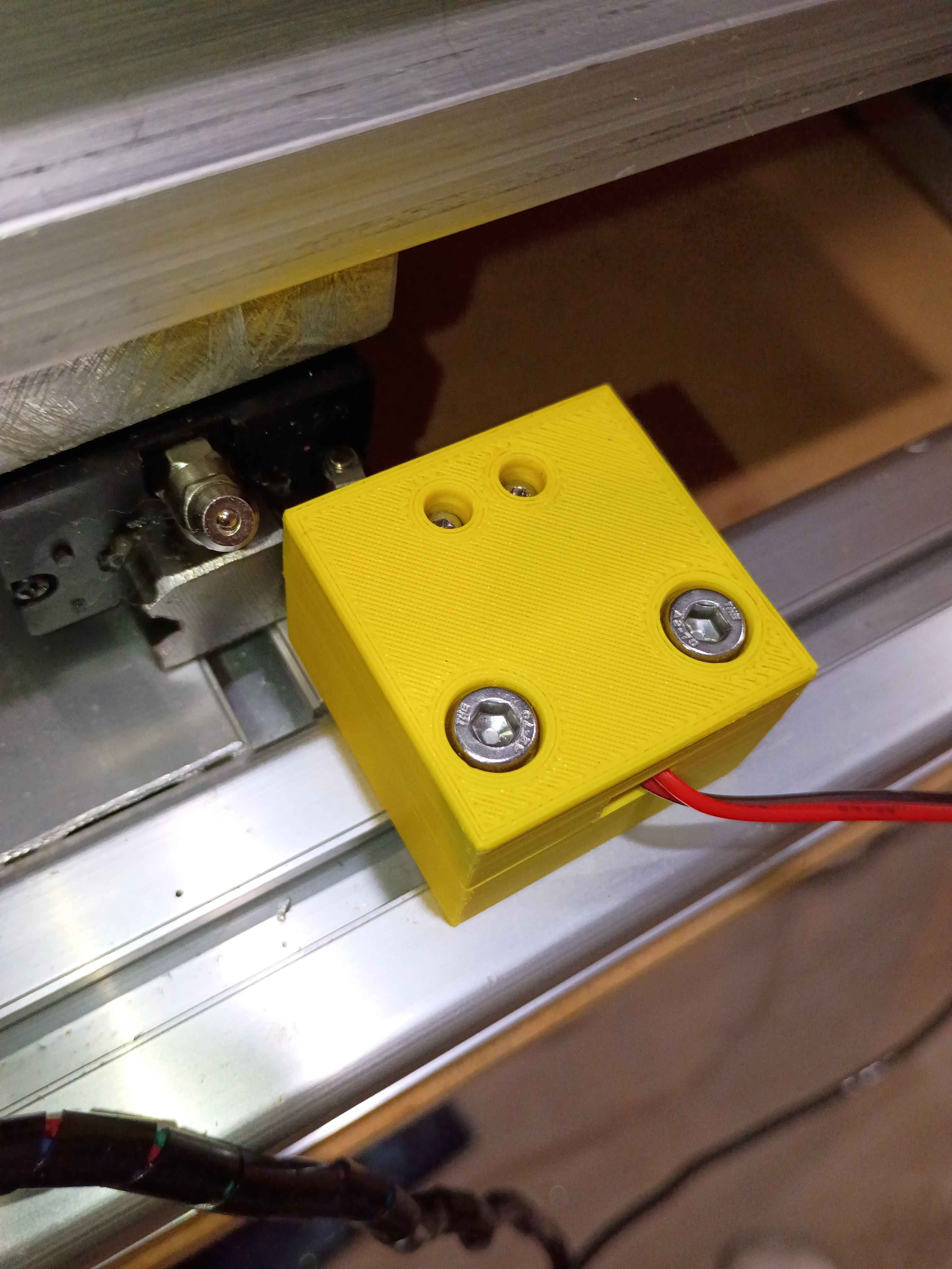
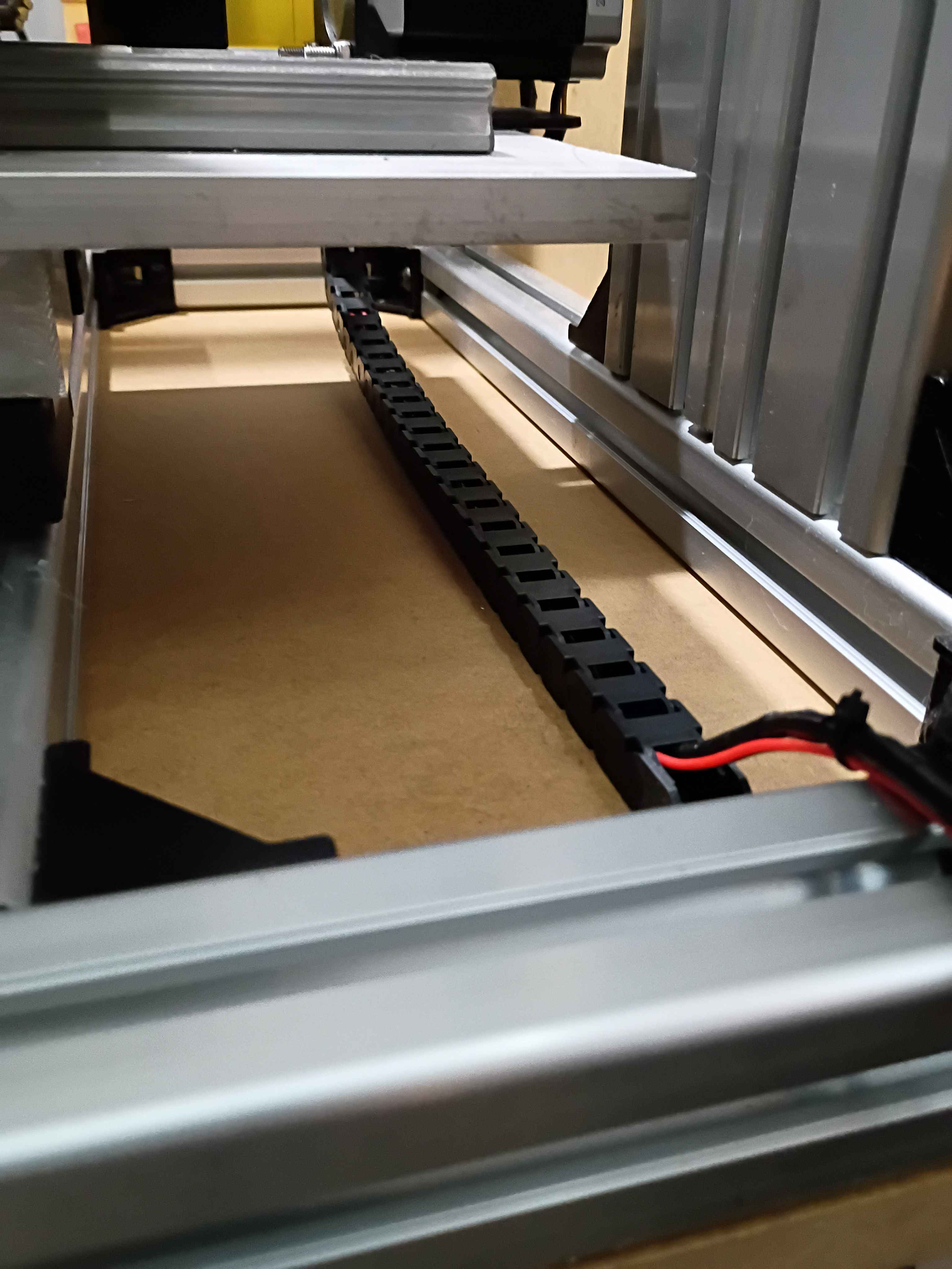
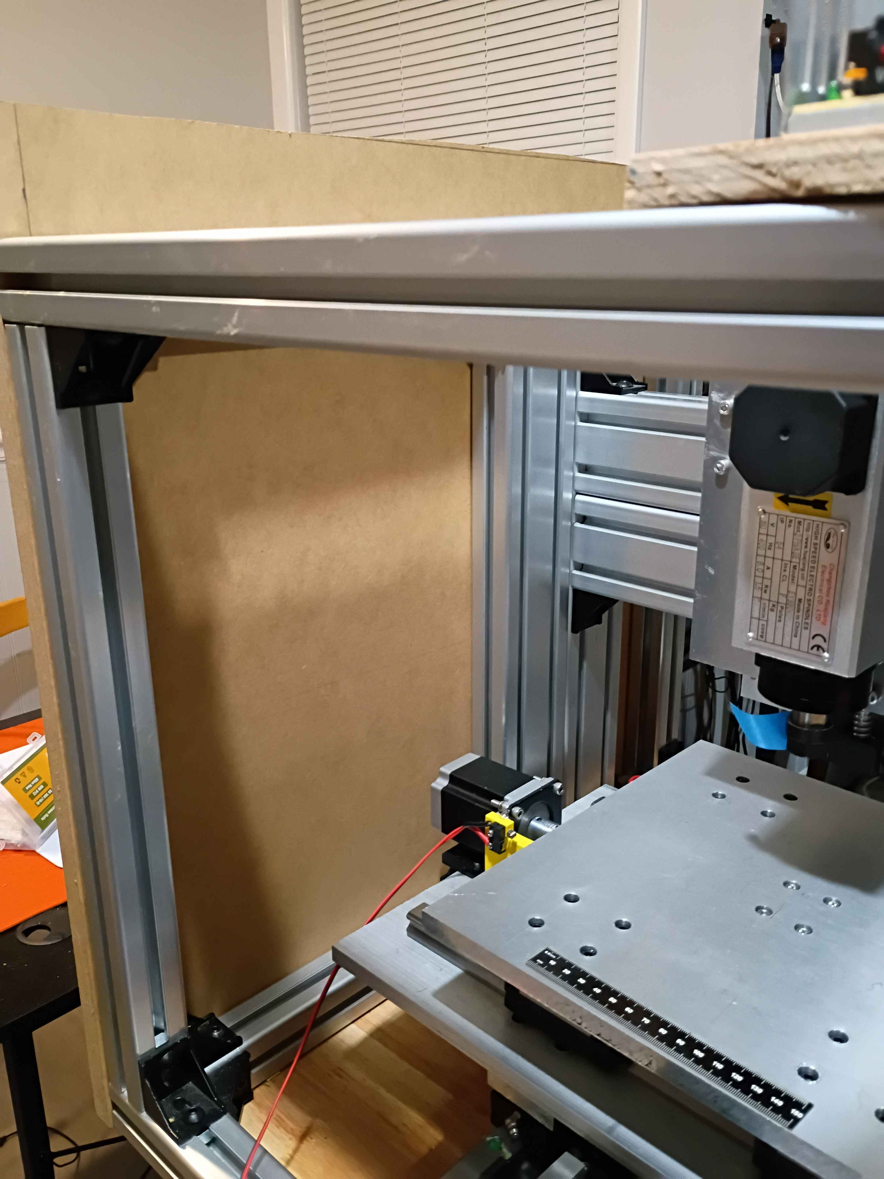
Installed y-axis drag chain. Drilled and installed right side enclosure panel. Designed and printed 2x 2-part limit switch mounts (00001-012 and 00001-013) for the x-axis motion, adding 4 inches of motion to the x-axis. Added some more wire wraps and adjusted some electrical connections. 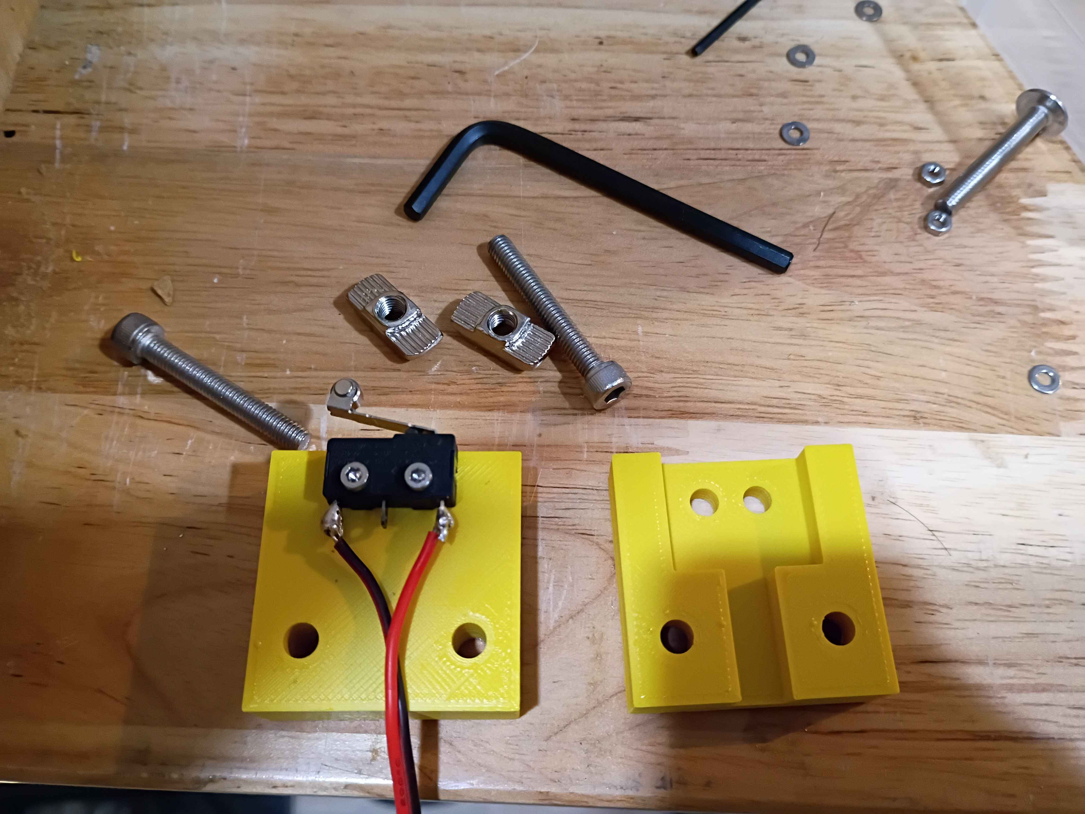
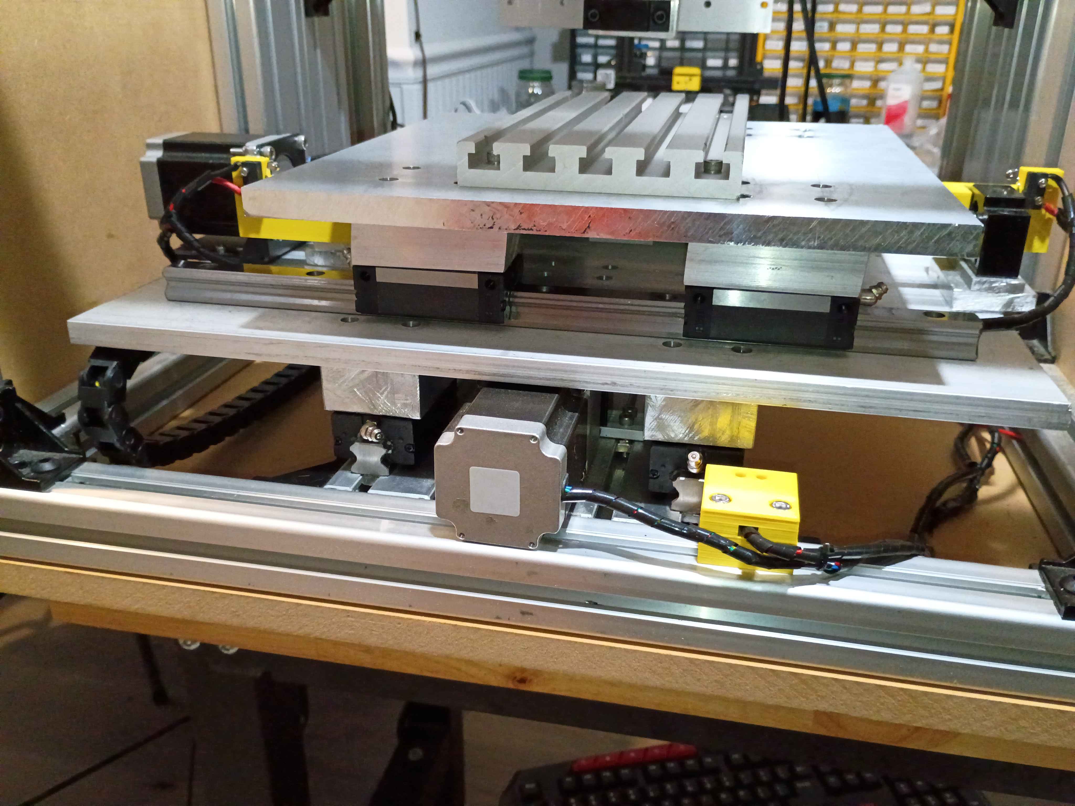
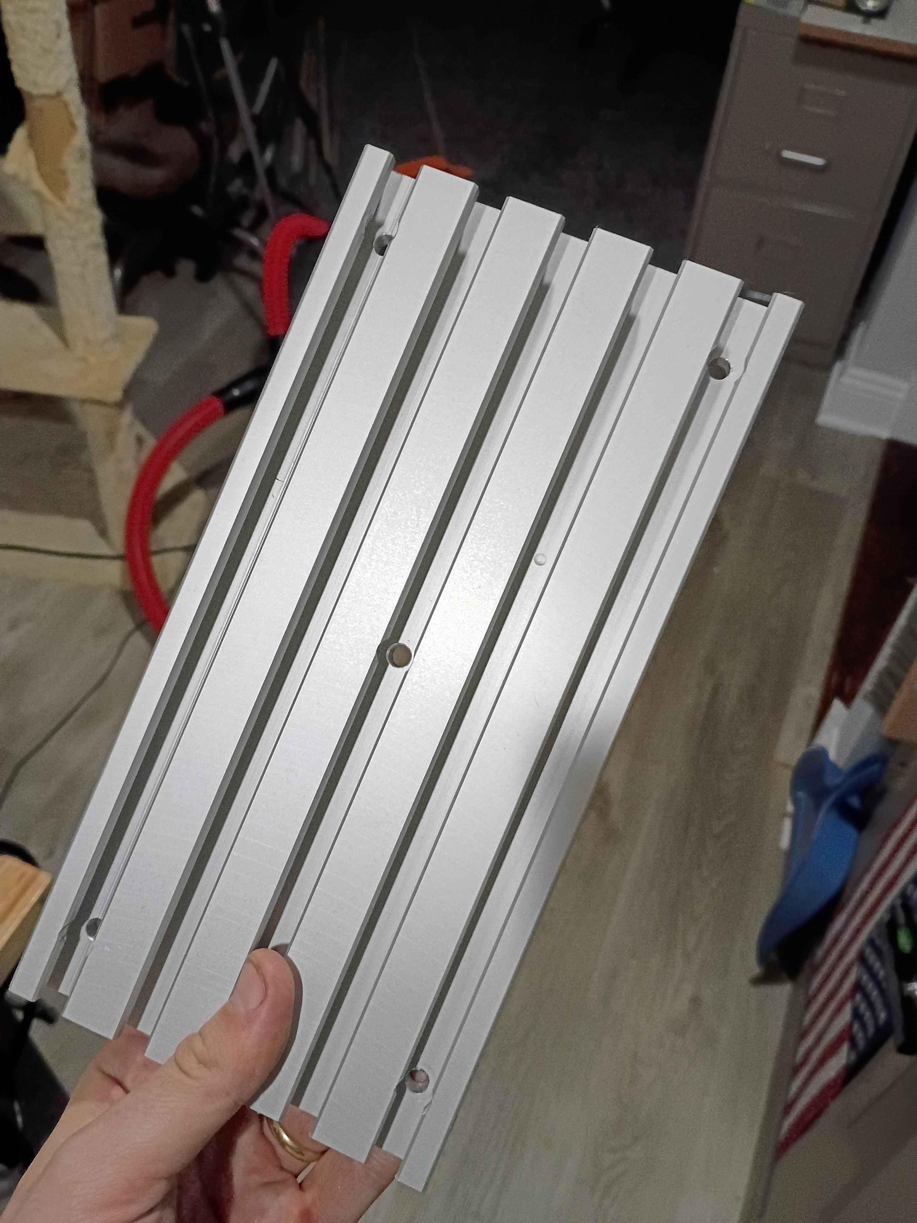
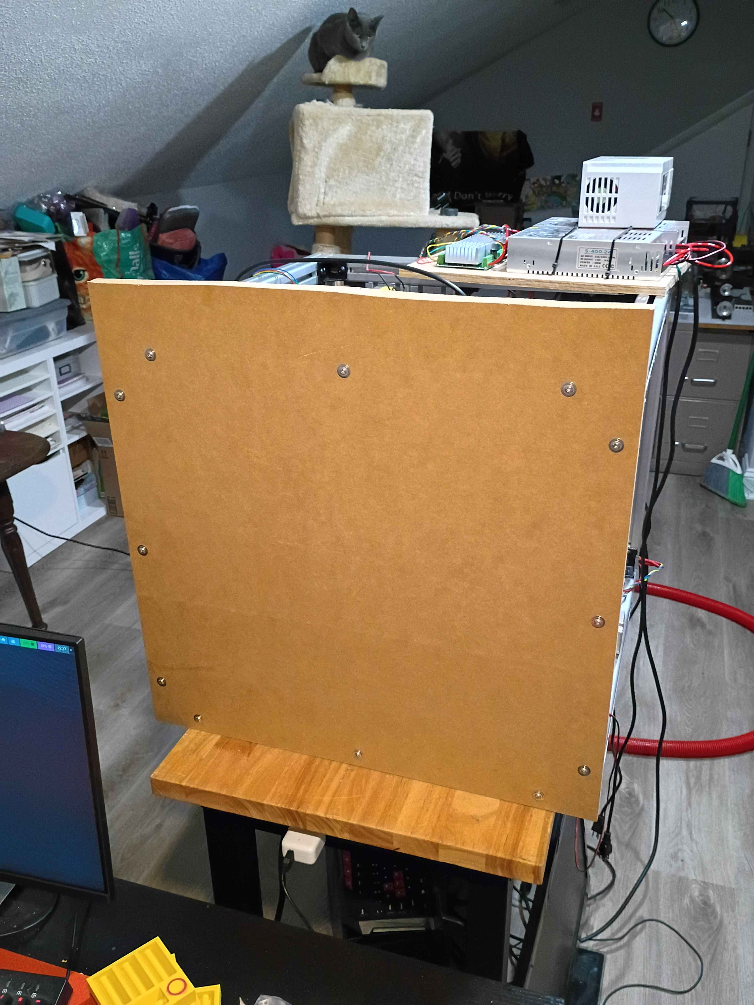
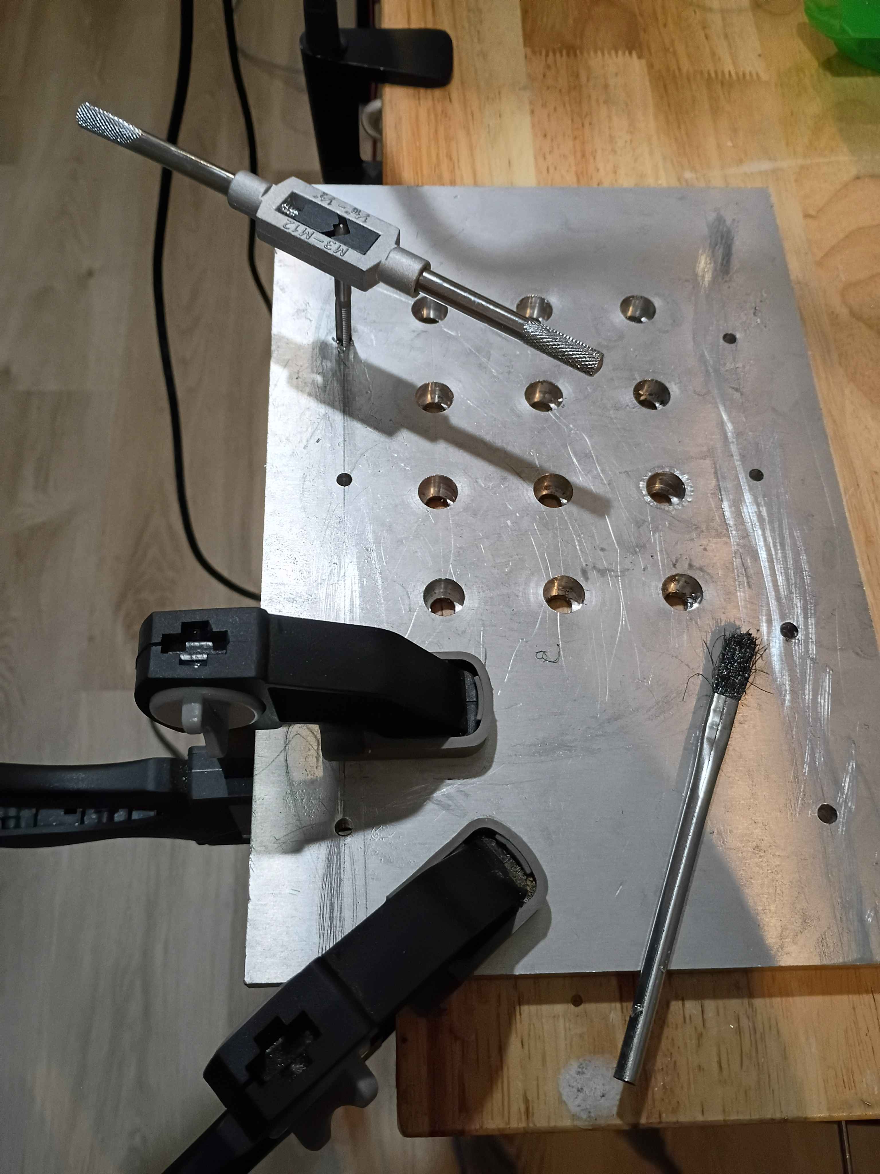
Drilled and installed bottom enclosure panel along with rubber dampener feet. Drilled holes in t-slot fixture plate and drilled and tapped corresponding mounting holes in the xy-gantry plate. Temporarily installed the fixture plate, but it will need to be trimmed with shims. 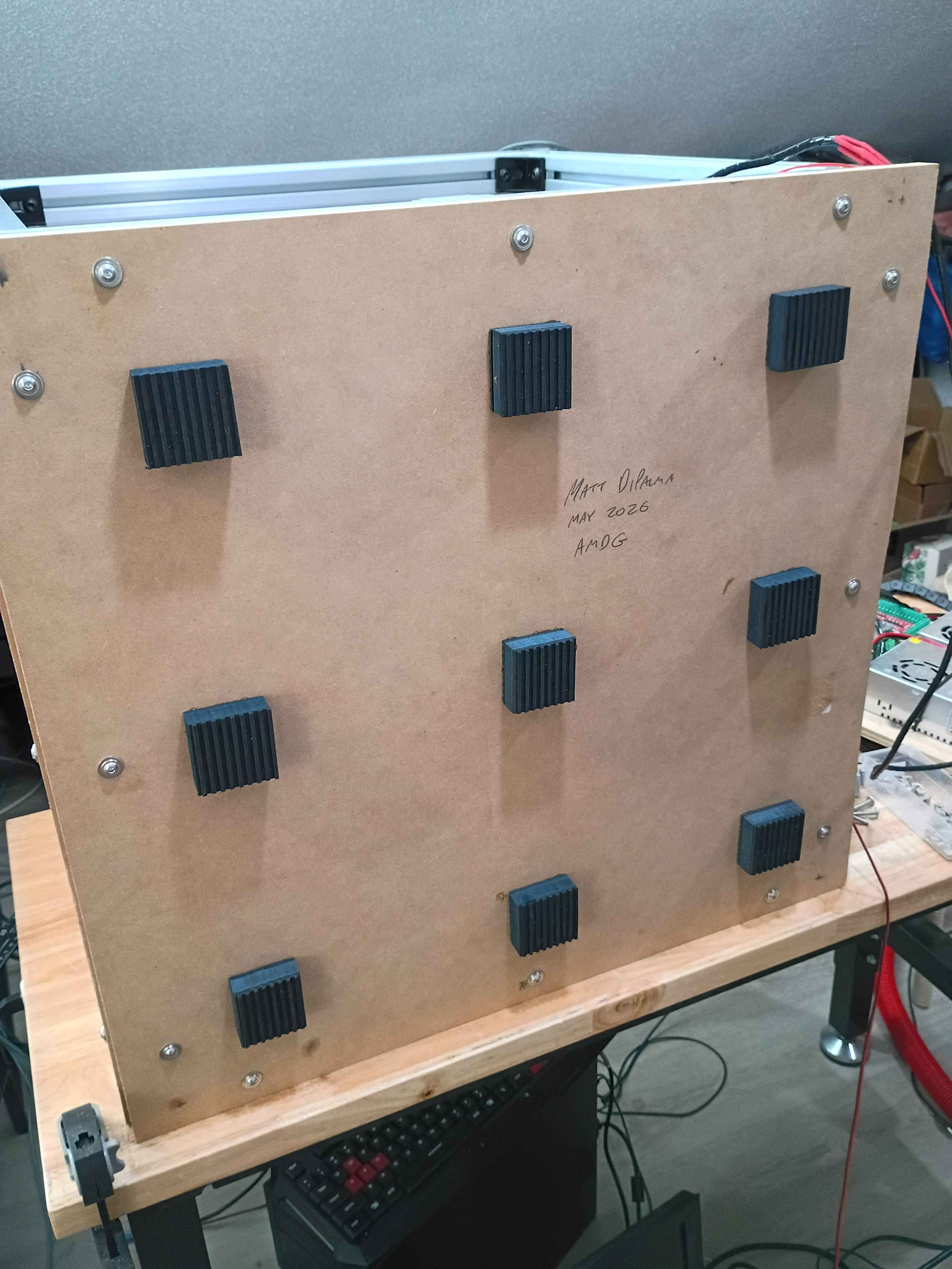
Got CNC to run gcode for a CAM path generated in FreeCAD See video of it running. Had to adjust the step count to 800 steps per mm for all axes because the drivers are set to 16x microstepping and the 1204 ballscrews have 4 mm pitch and the steppers generally have 200 steps per revolution so (16*200/4=800). Also wrapped the stepper lead wires in protective wire wrap. 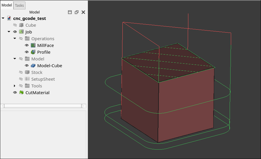
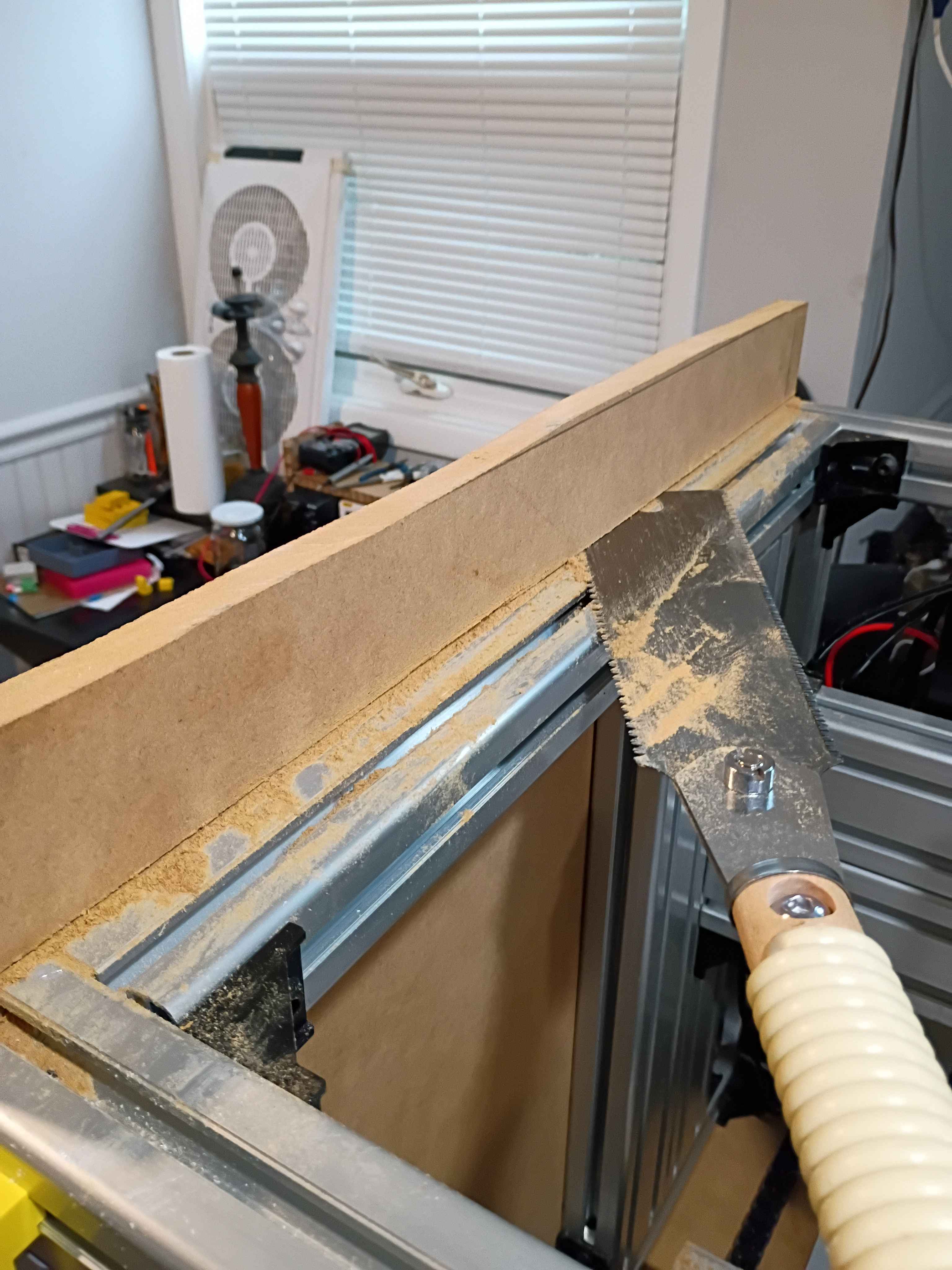
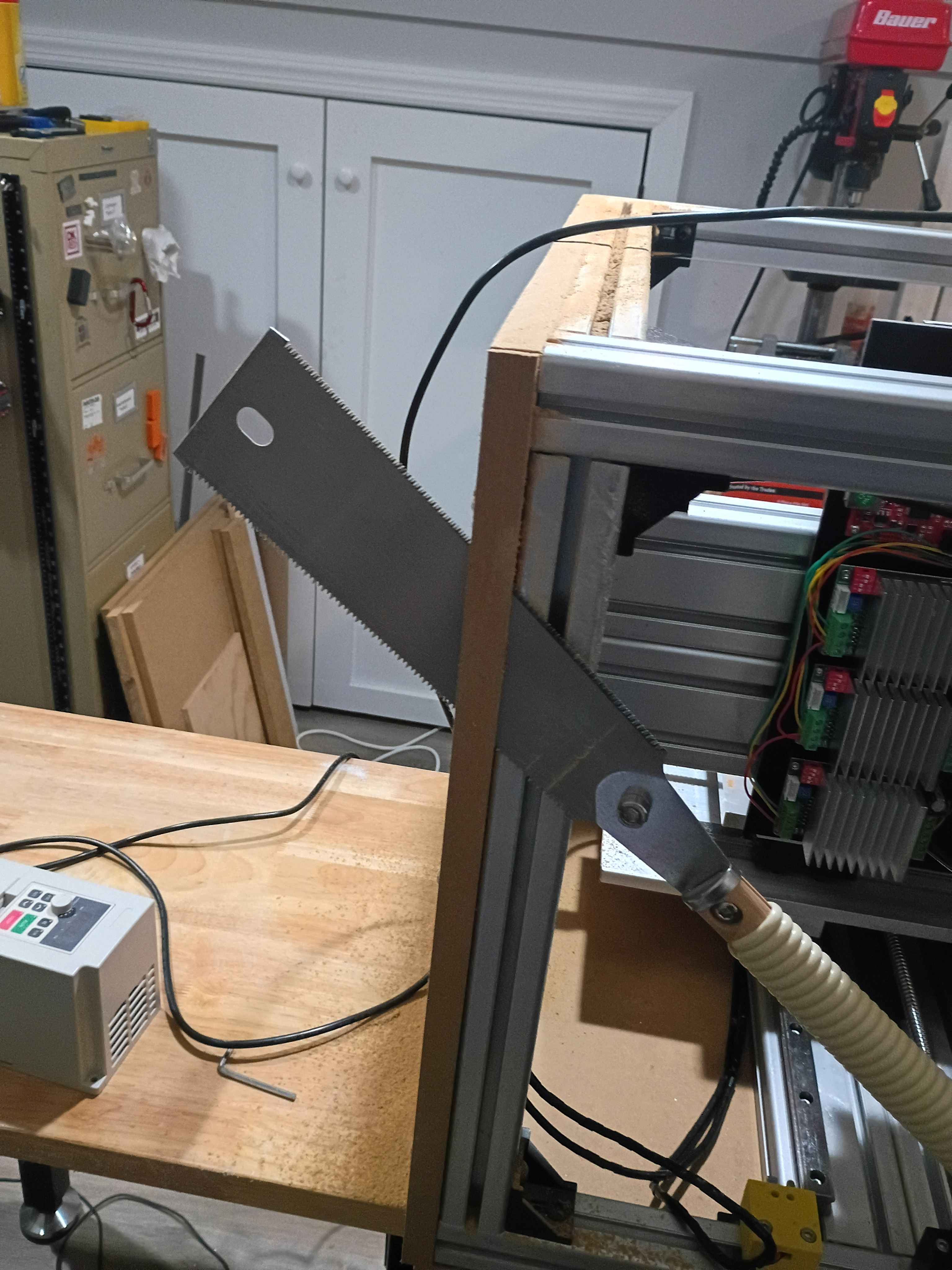
Finished sawing all 6 panels for the enclosure. Drilled holes and installed one side panel with flange bolts, fat washers, and t-nuts. I decided to put the excess material on the top to make some little container to hold things up there. I am holding off on doing the remainder of the enclosure until I know it works. 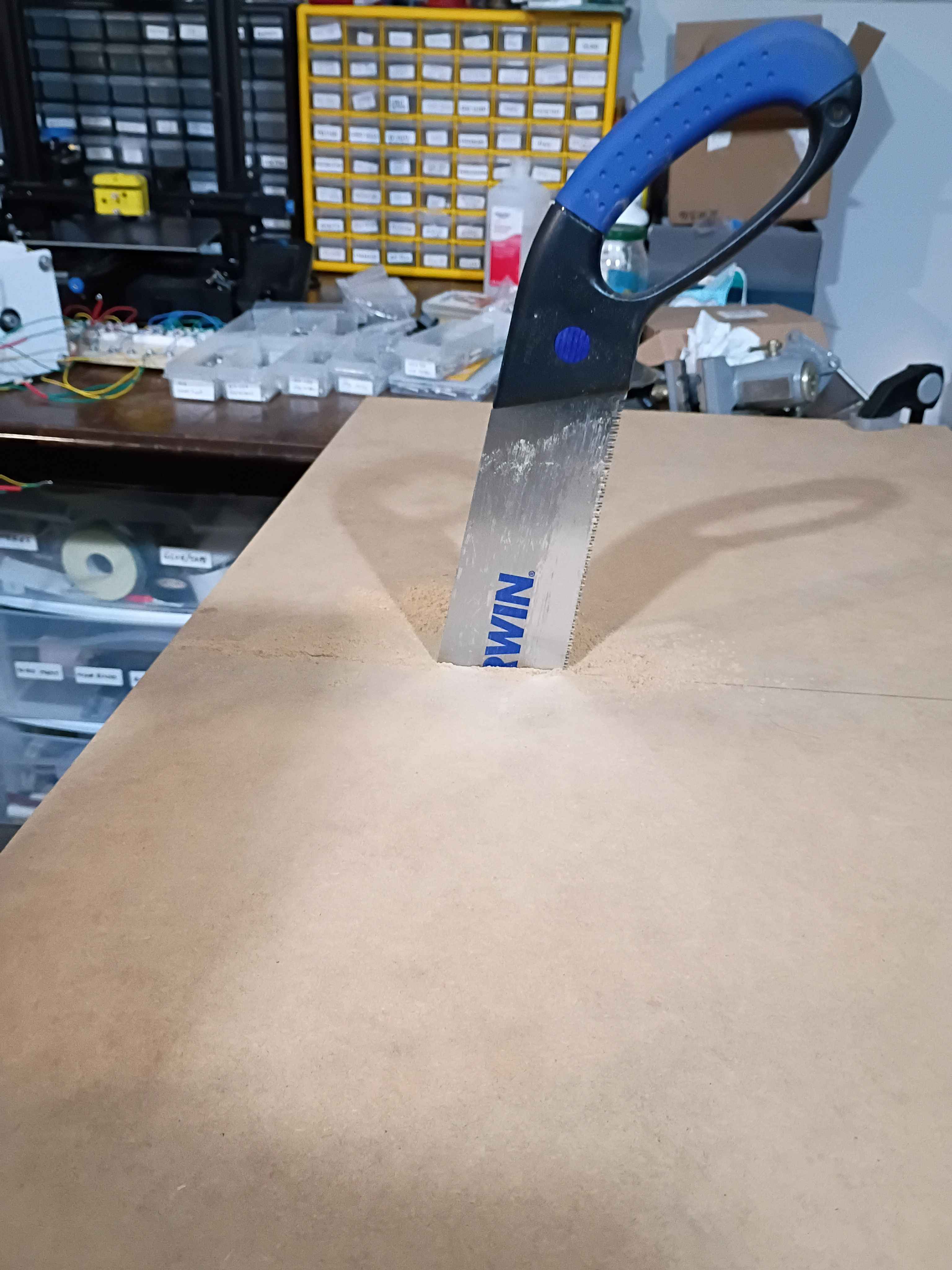
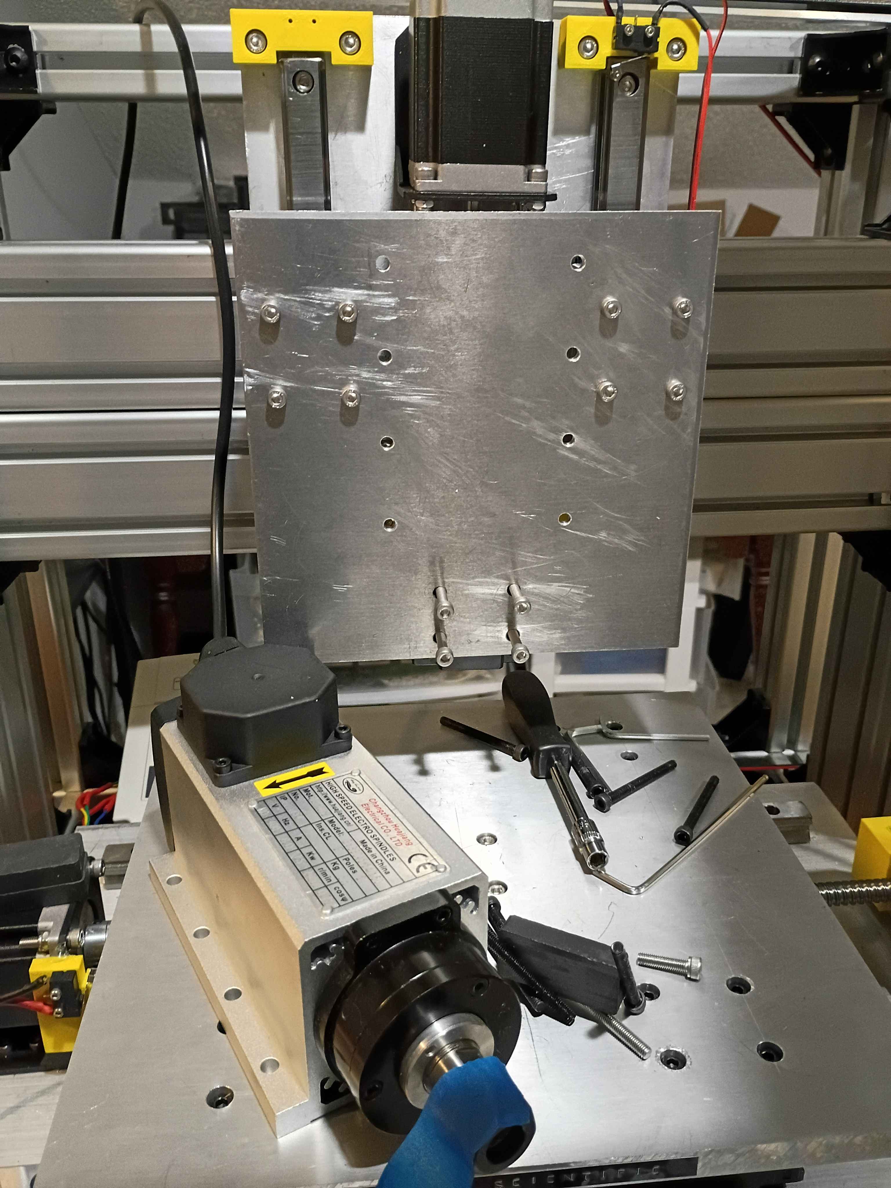
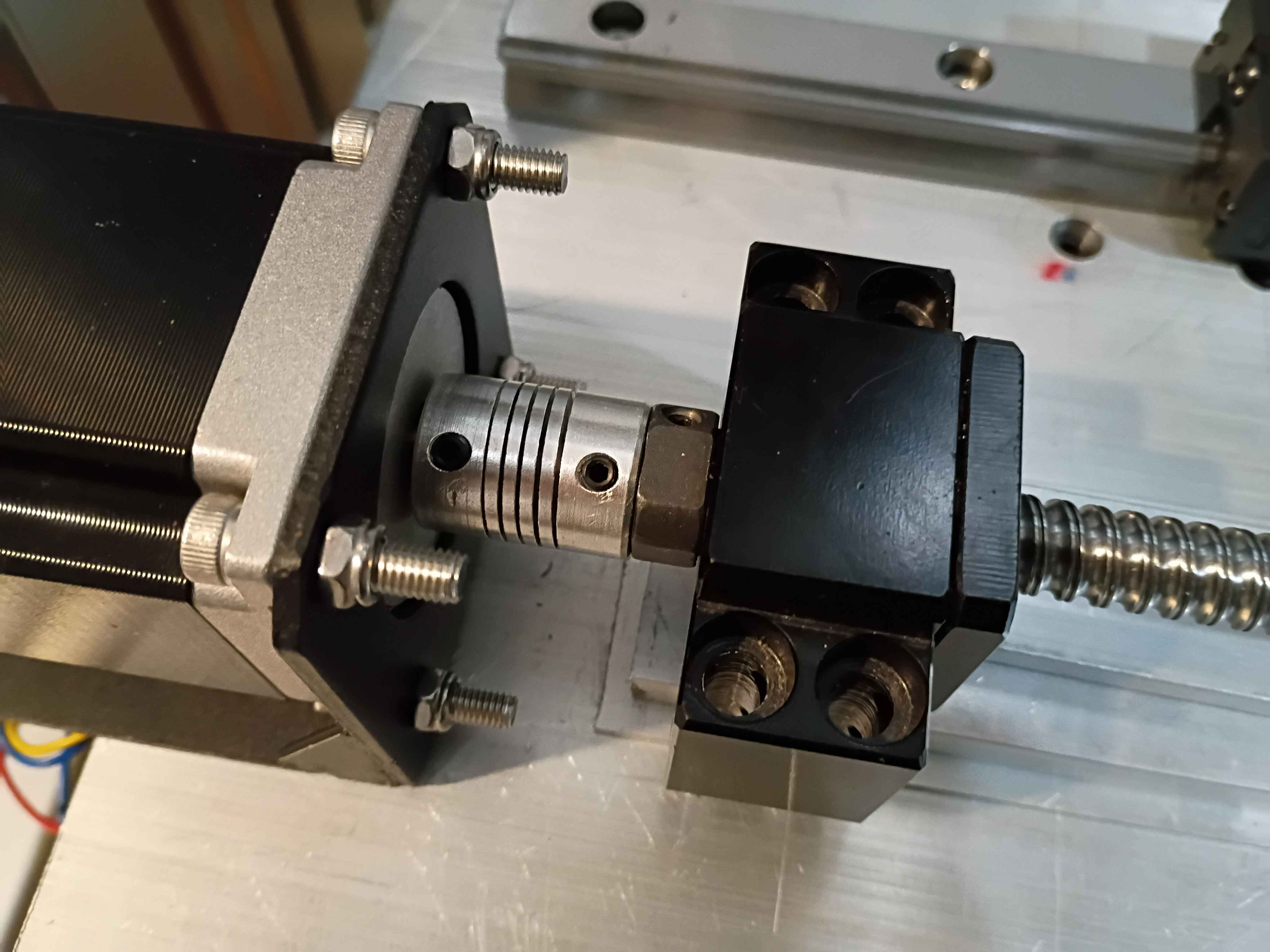
Bolted up the rest of the z-axis linear motion components including the spindle, configured all the electronics and software, and did a successful dry run. The stepper driver board that I had installed was bad, but thankfully I had an extra. In the future, the x axis motion can be extended slightly, and the z-axis downward limit switch is around 45mm beyond the feasible range of motion, so if that is to be used, some alternate stoppers and limit switch mounts will need to be printed. 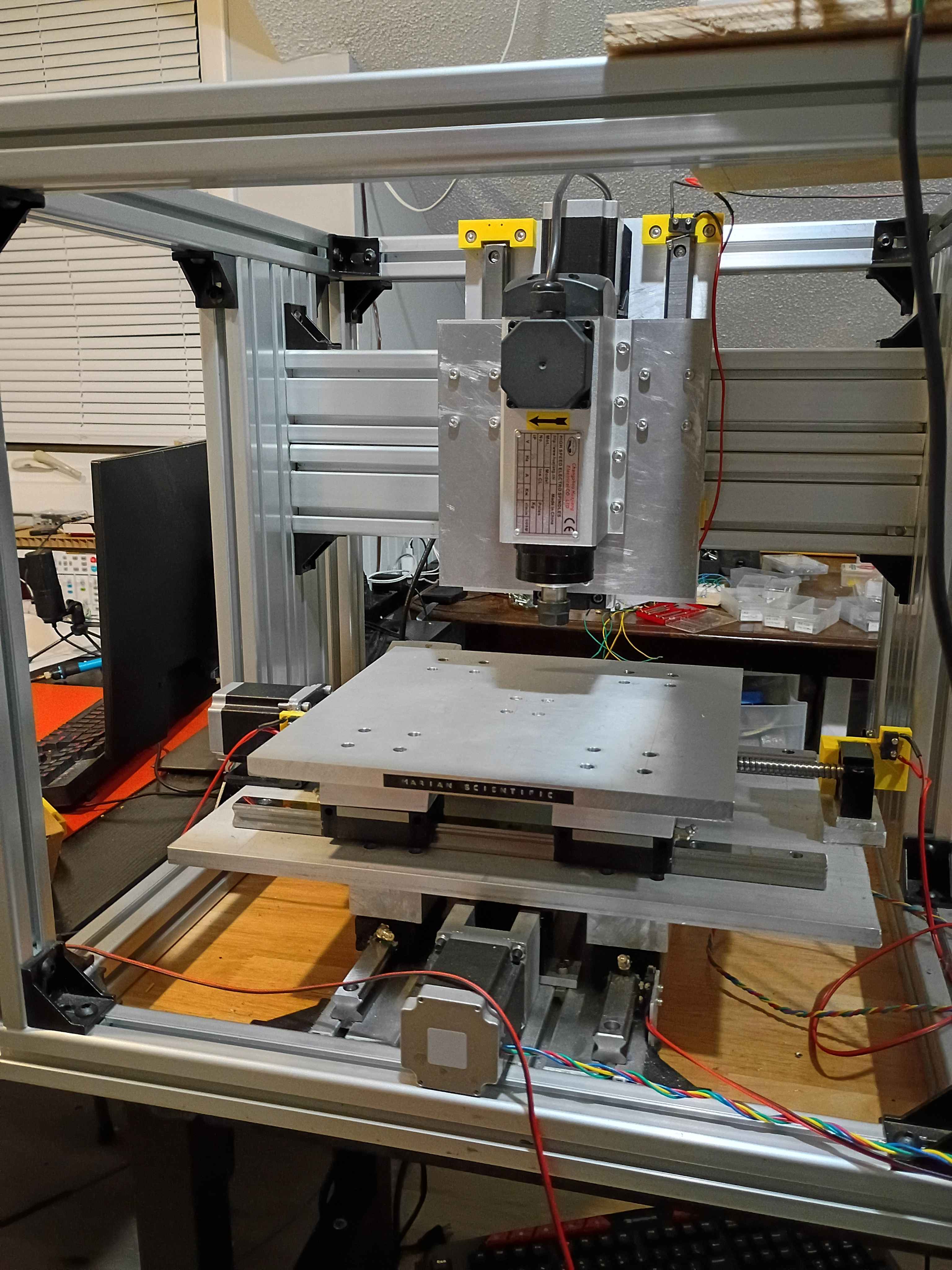
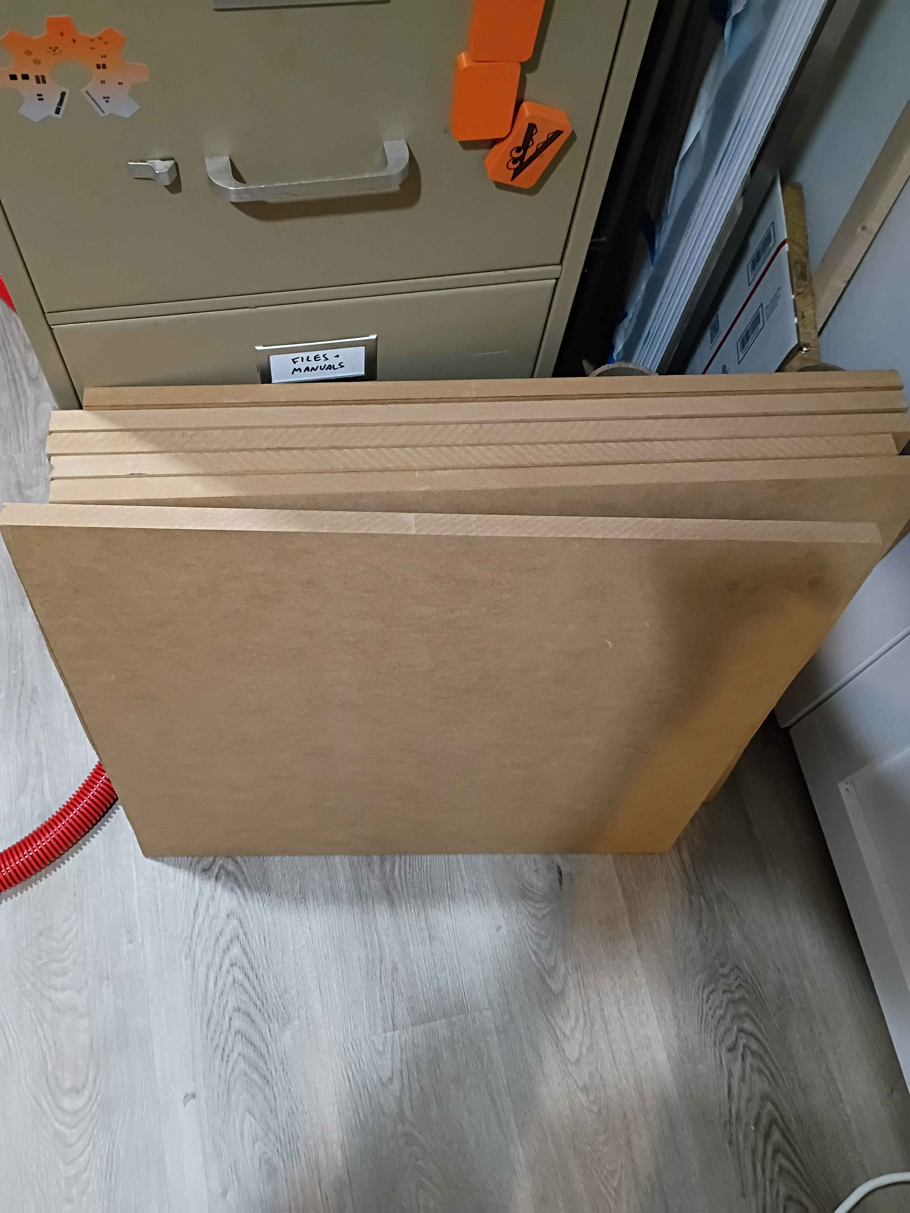
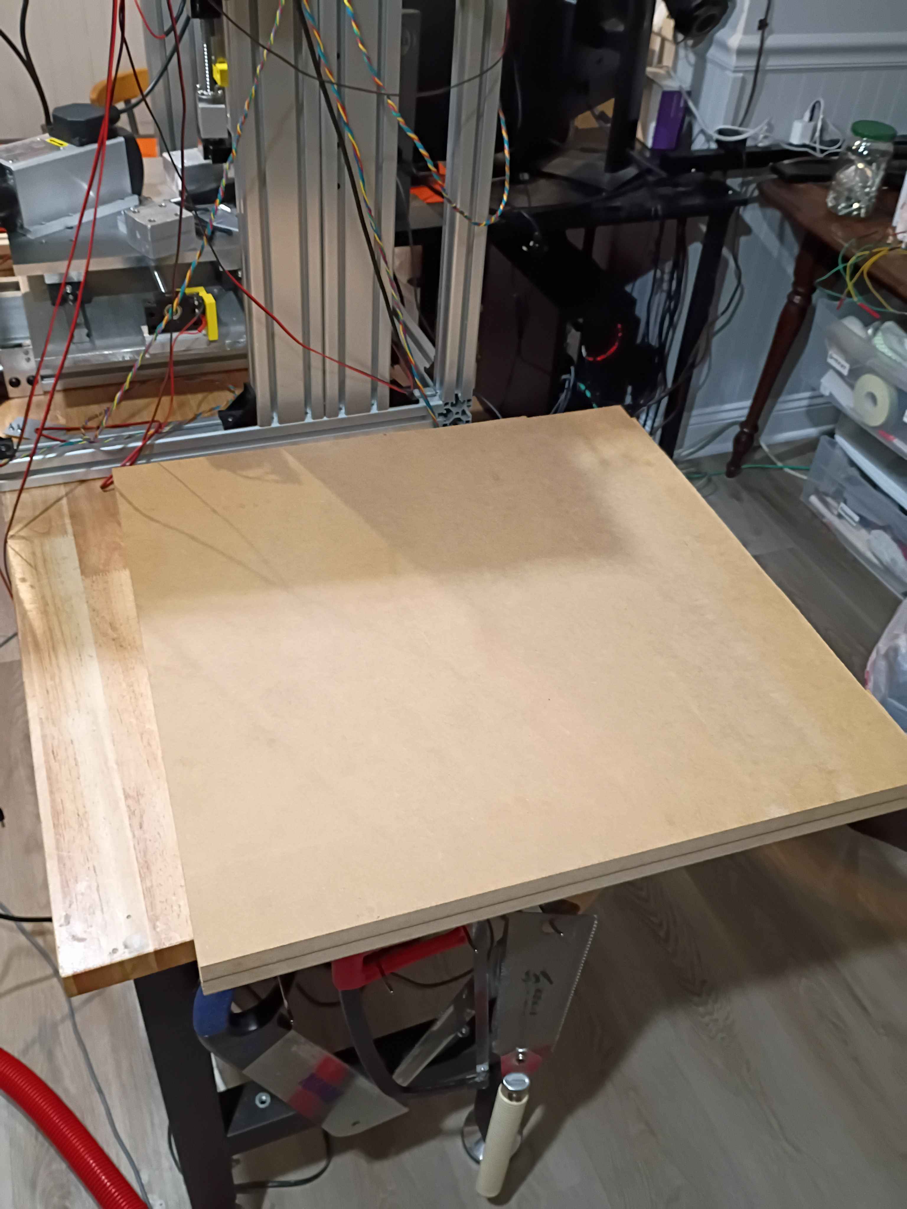
Purchased and cut two 24x~24x3/4" panels from MDF for the top and bottom enclosure walls. Widened the holes in 2 of the spacers and did a dry fit of the Z mount plate. I will probably need washers or something or to file down some of the stepper bracket, as they slightly interfere when the carriages slide upward enough. 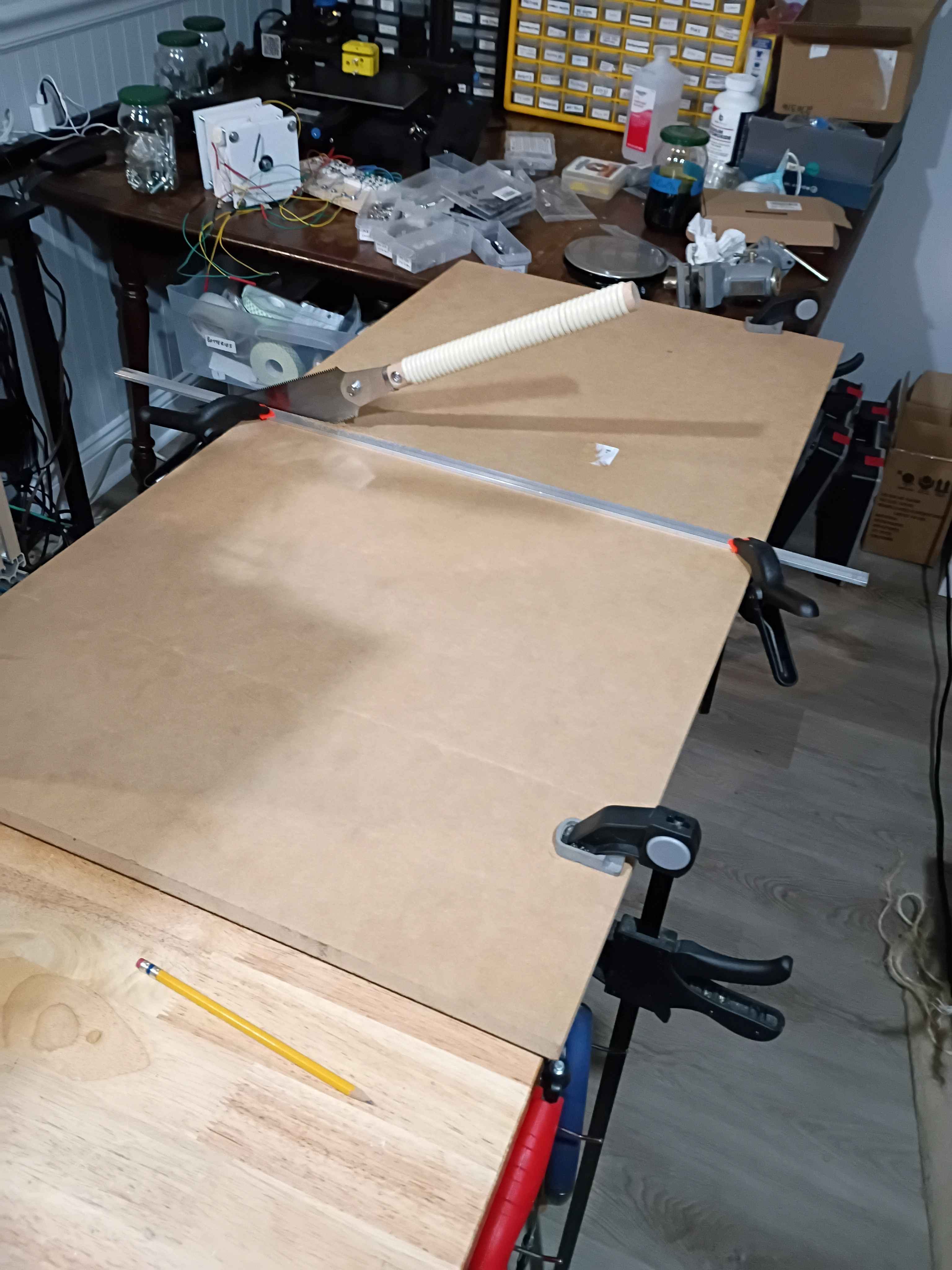
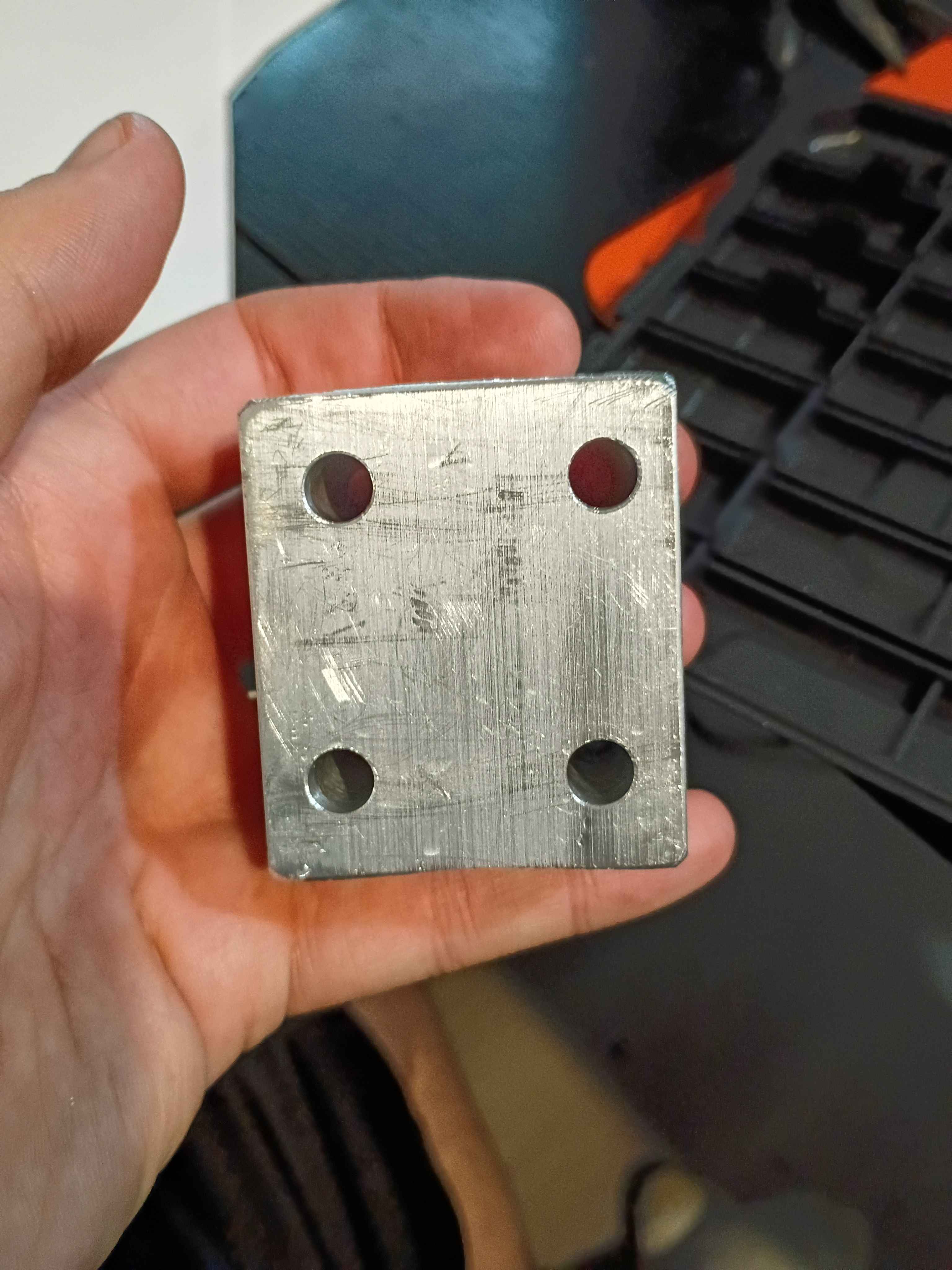
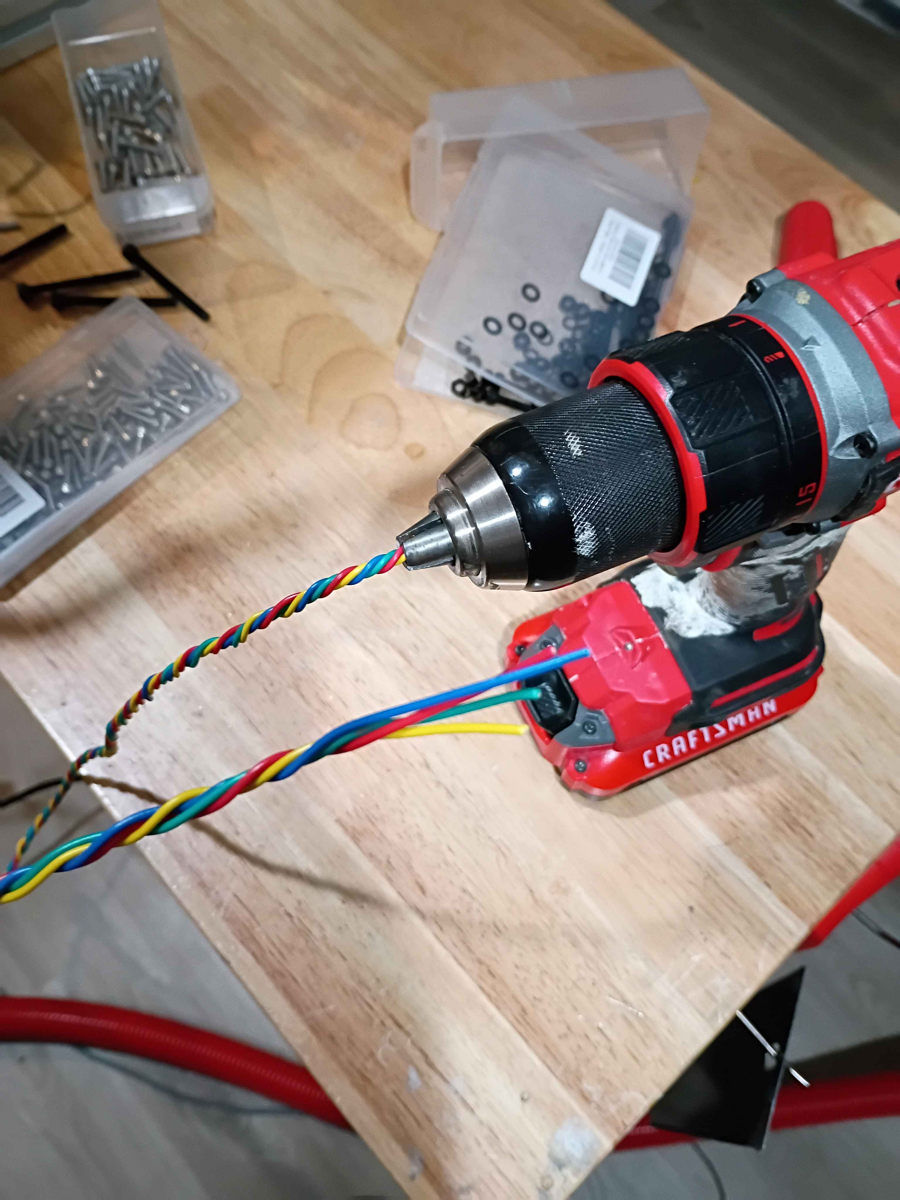
Cut and drilled last spacer. Marked (by printing a template) a drilled the Z-axis mount plate. Realized an earlier carriage spacer had holes that were not straight thru since the part was 2" thick and drill bit deviated as it cut, so I opened those 5.5mm holes to 8mm. Connected all Z-direction motion wiring. Used a power drill to coil the stepper motor lead wires (very cool). Also wired the VFD and spindle motor and did a quick test. 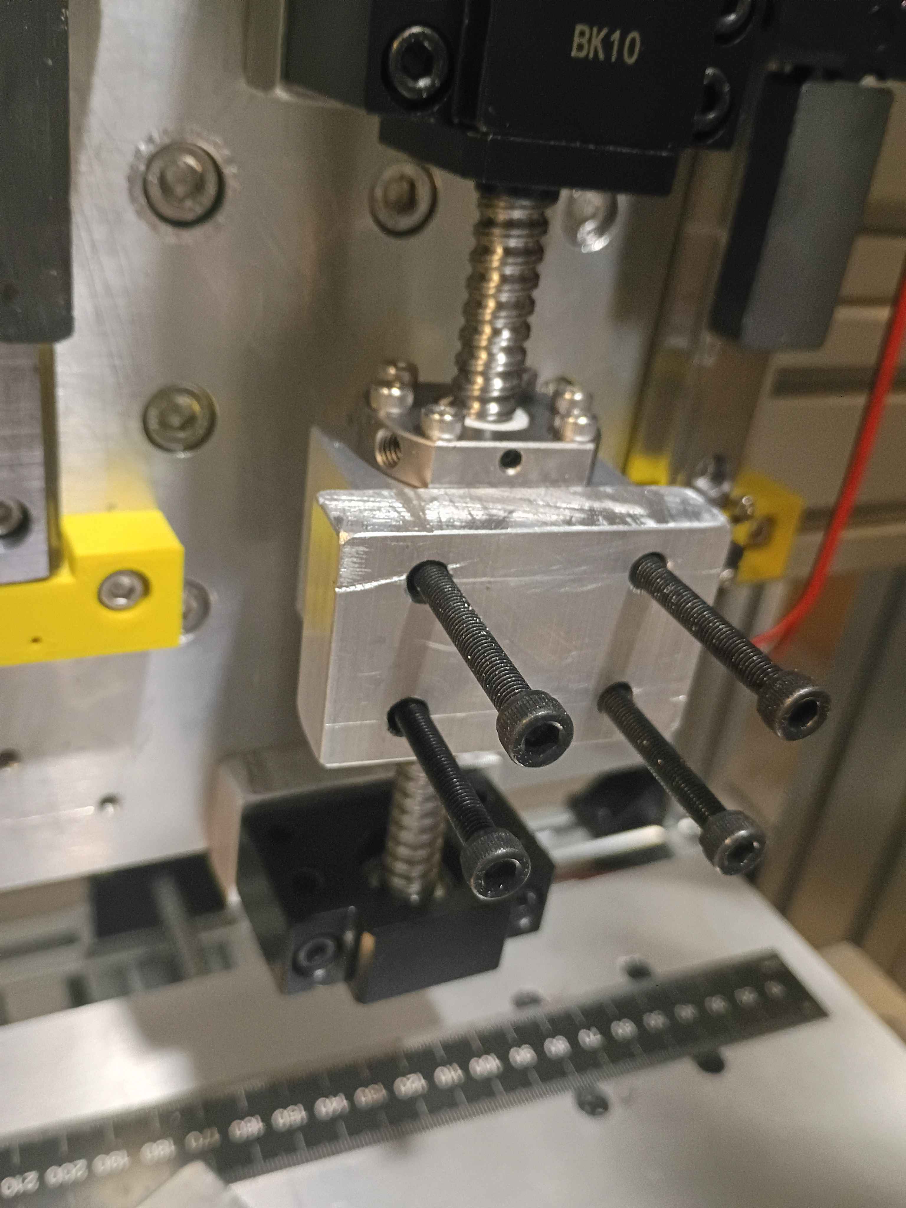
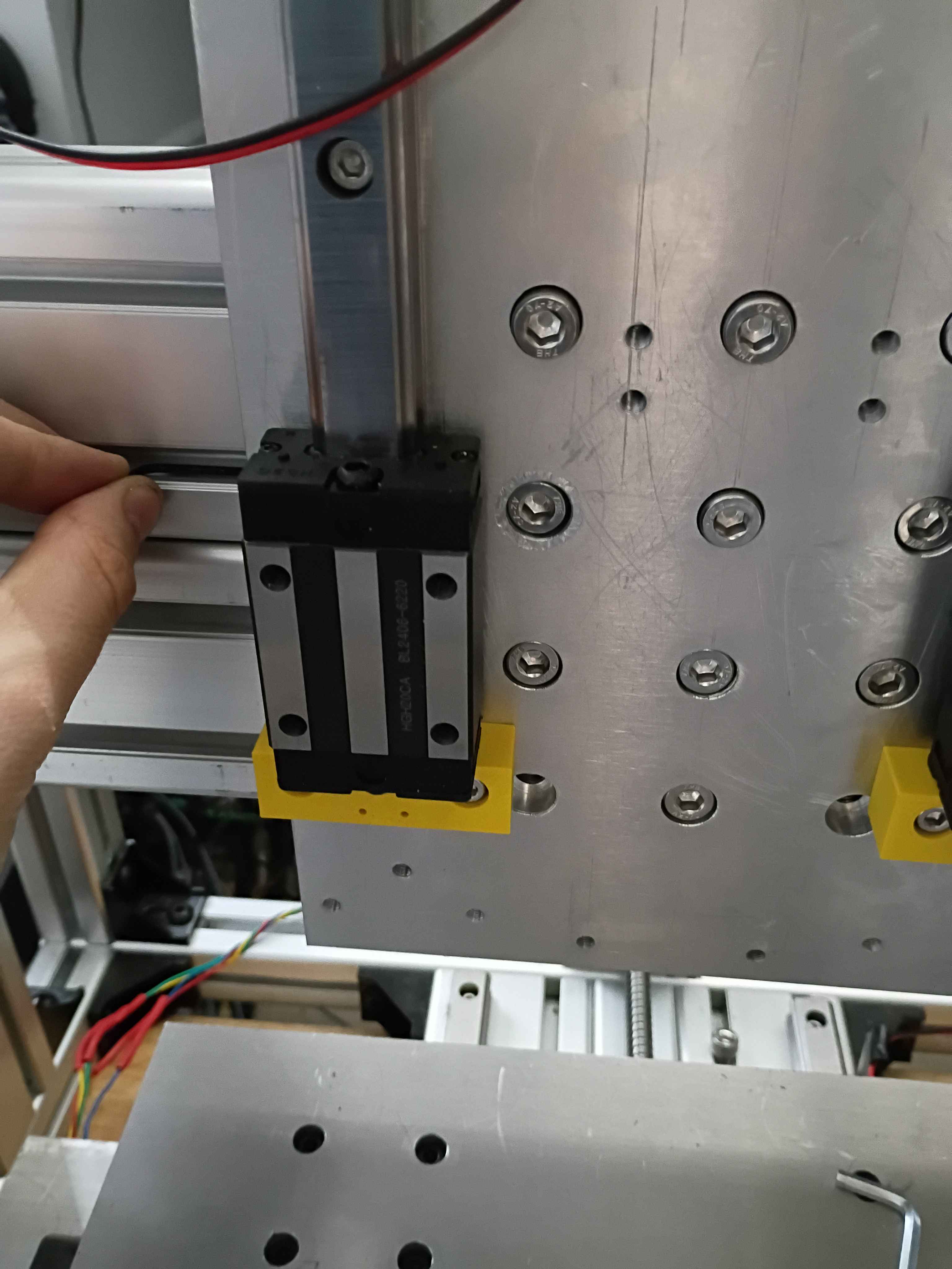
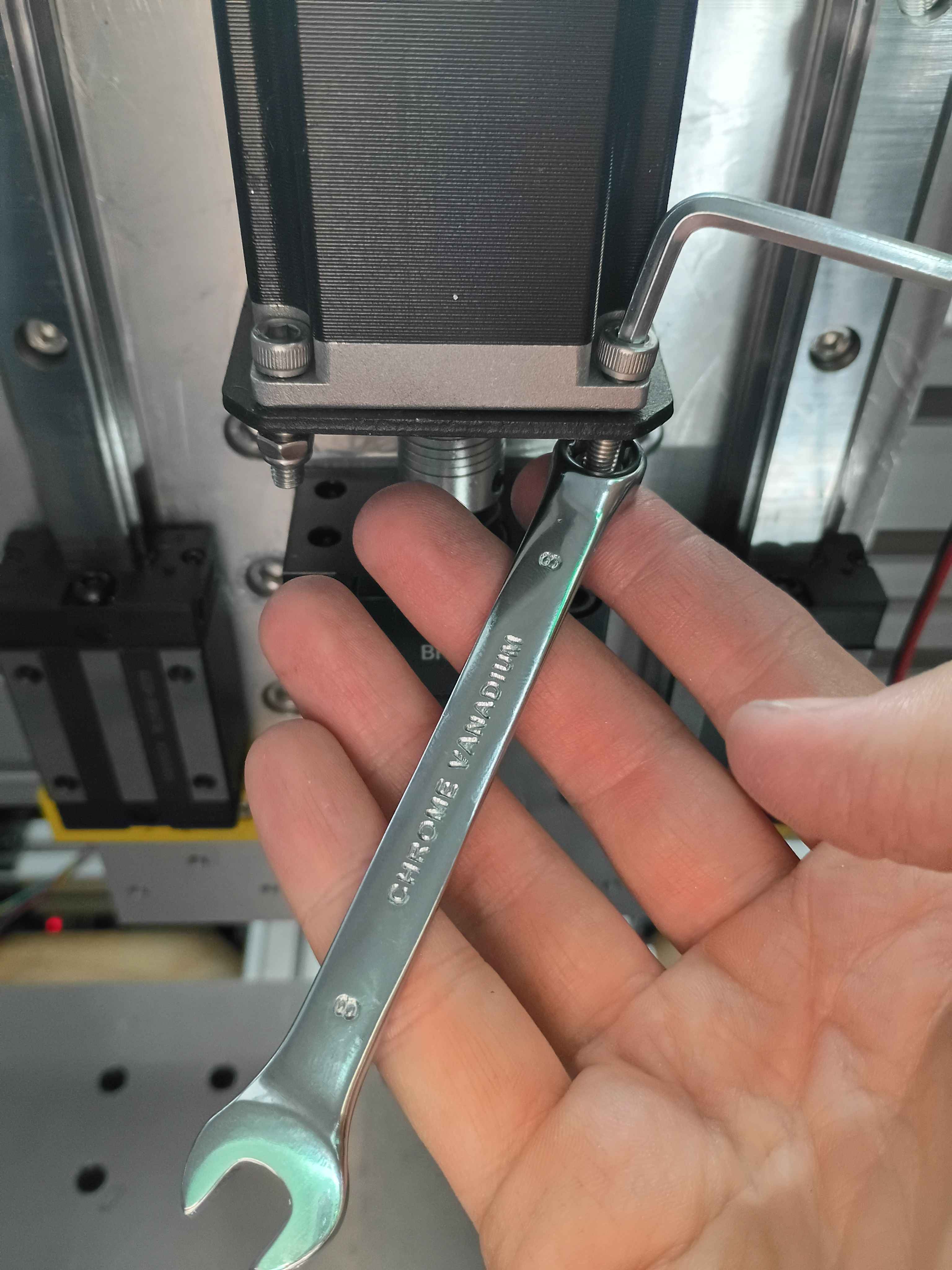
Redrilled and retapped holes for the stepper motor mount and reinstalled all the components. Used plastic to tape off the linear rails during the rework to prevent having to completely disassemble everything, while still keeping chips and dust out of the linear rail carriages. Learned that you can use a long Allen wrench to press deep-set T-slot nuts into the proper orientation (and position) while attempting to screw into them, helping avoid them getting stripped by accident. Also learned that you can use your finger in the round end of a wrench to get the right depth when trying to screw a nut onto the end of a bolt. 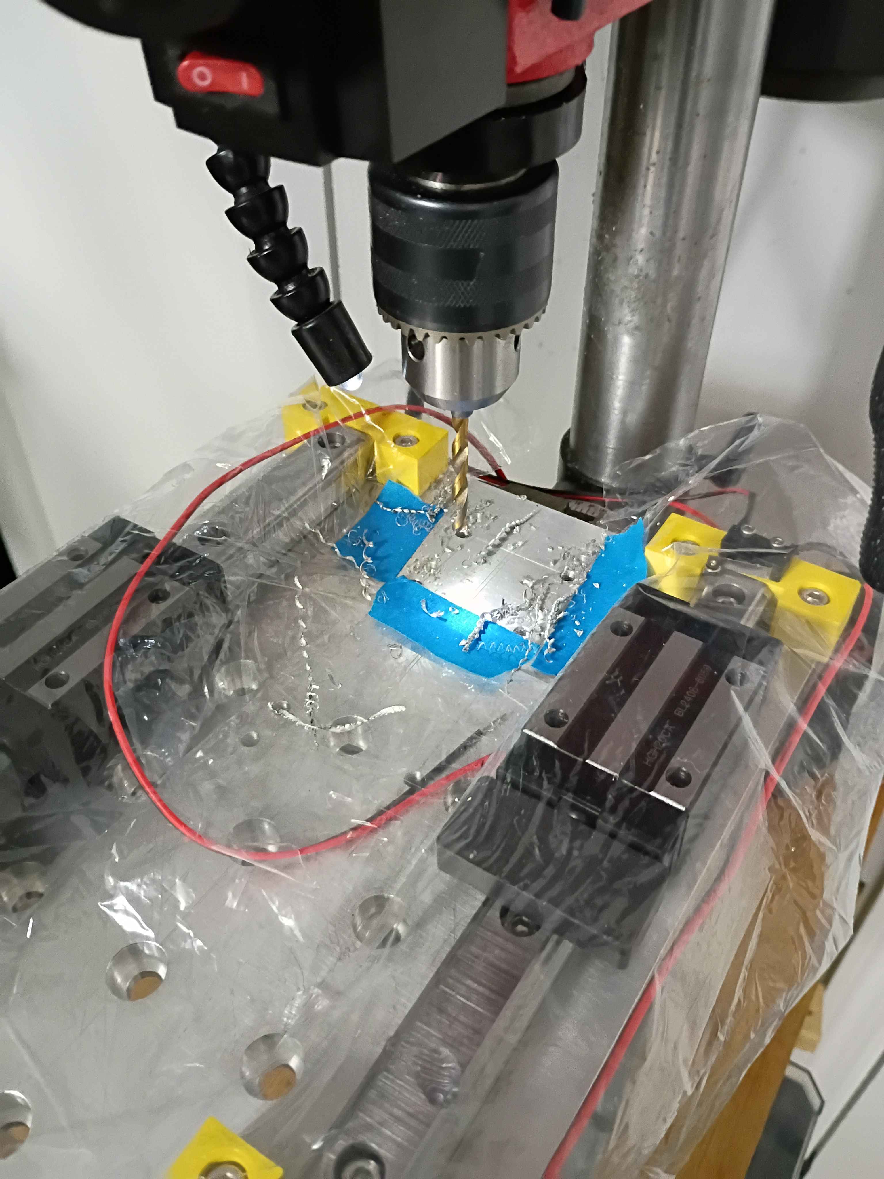
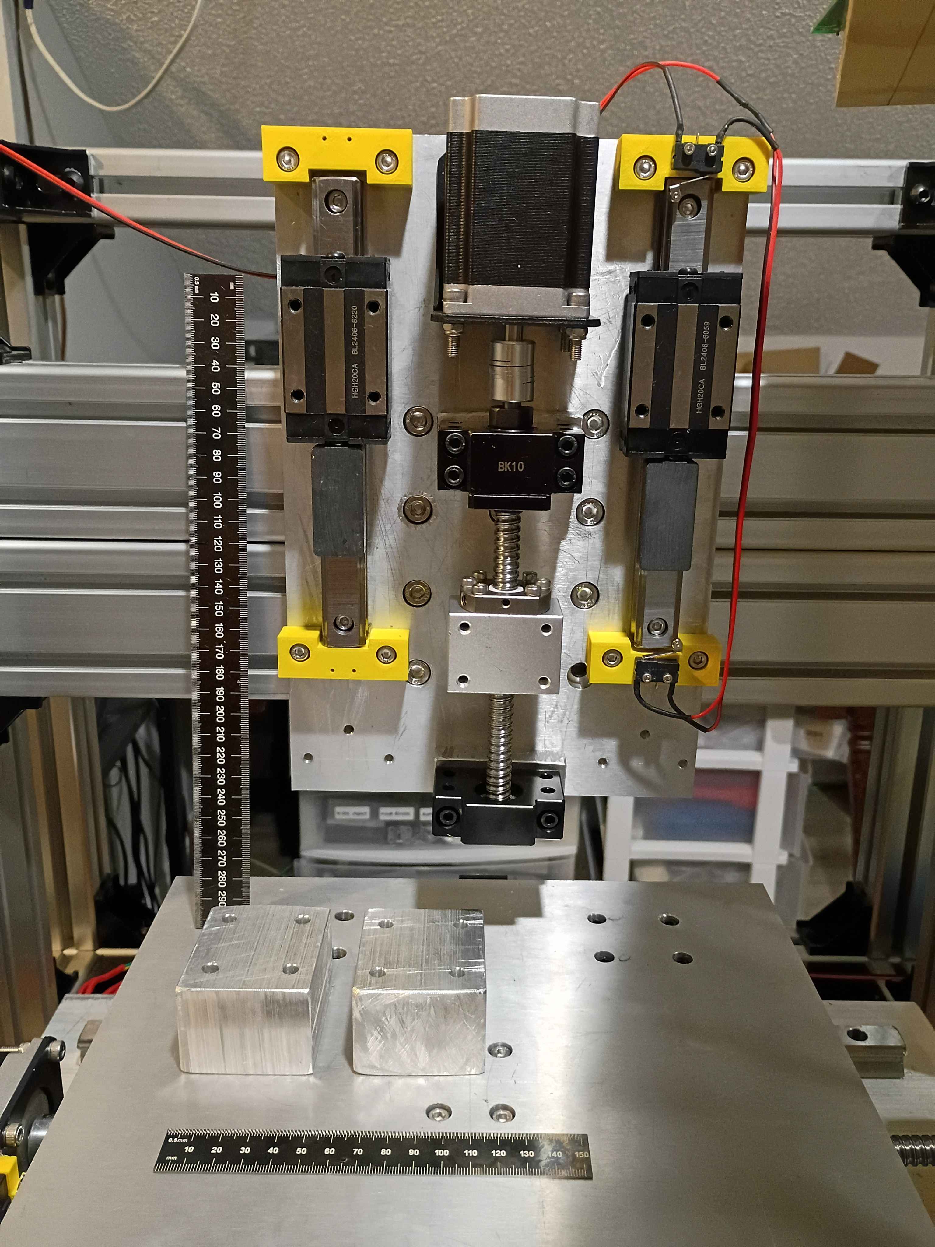
Did a lot for the z-axis linear motion system. I will need to disassemble and redrill 4 holes for the stepper motor mount because they are too close to the ballscrew. And I think I might possibly drill an access hole to remove an M8 t-slot nut embedded in the Aluminum extrusion that has faulty threads to replace it without having to disassemble the entire frame assembly. 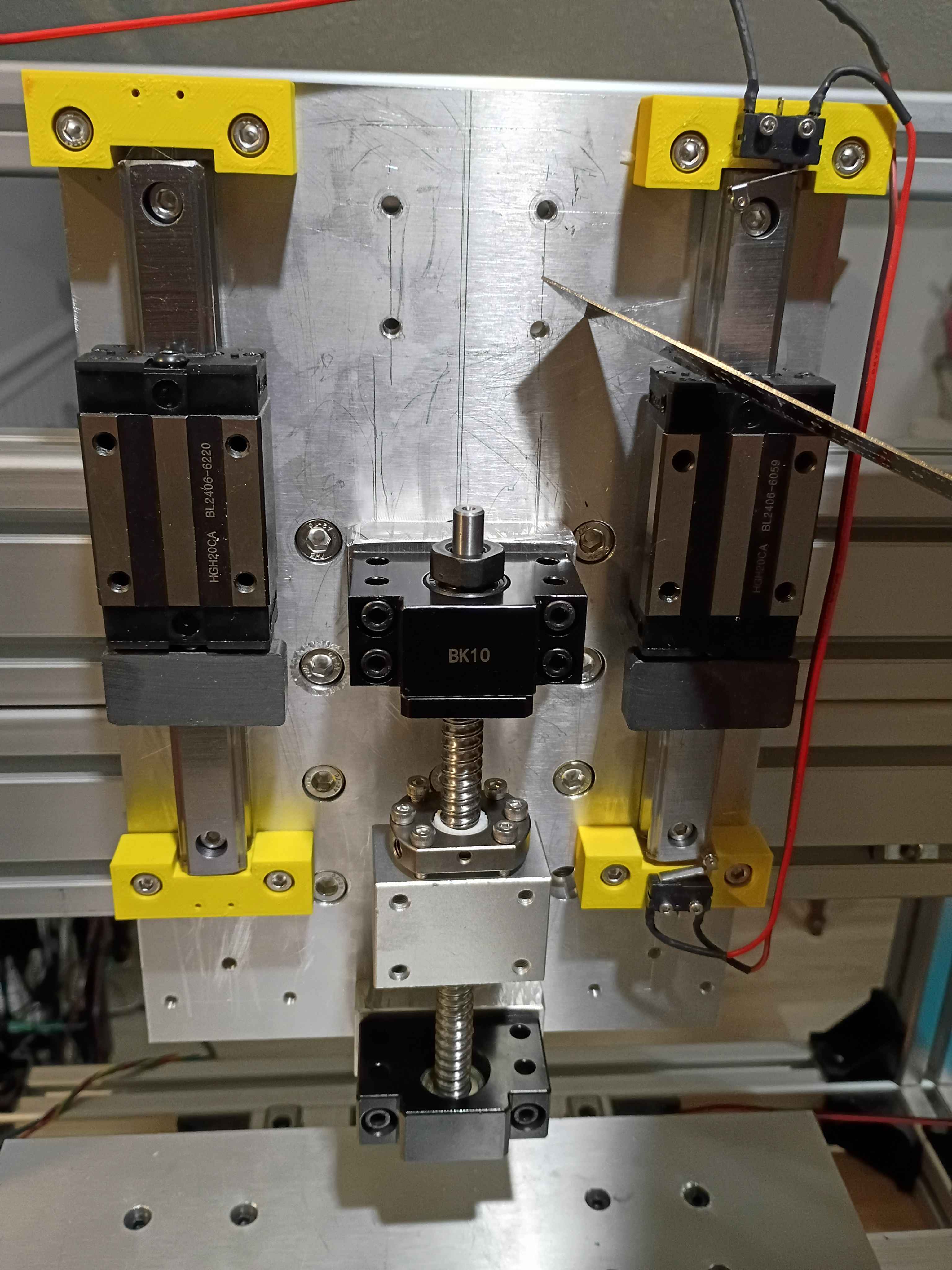
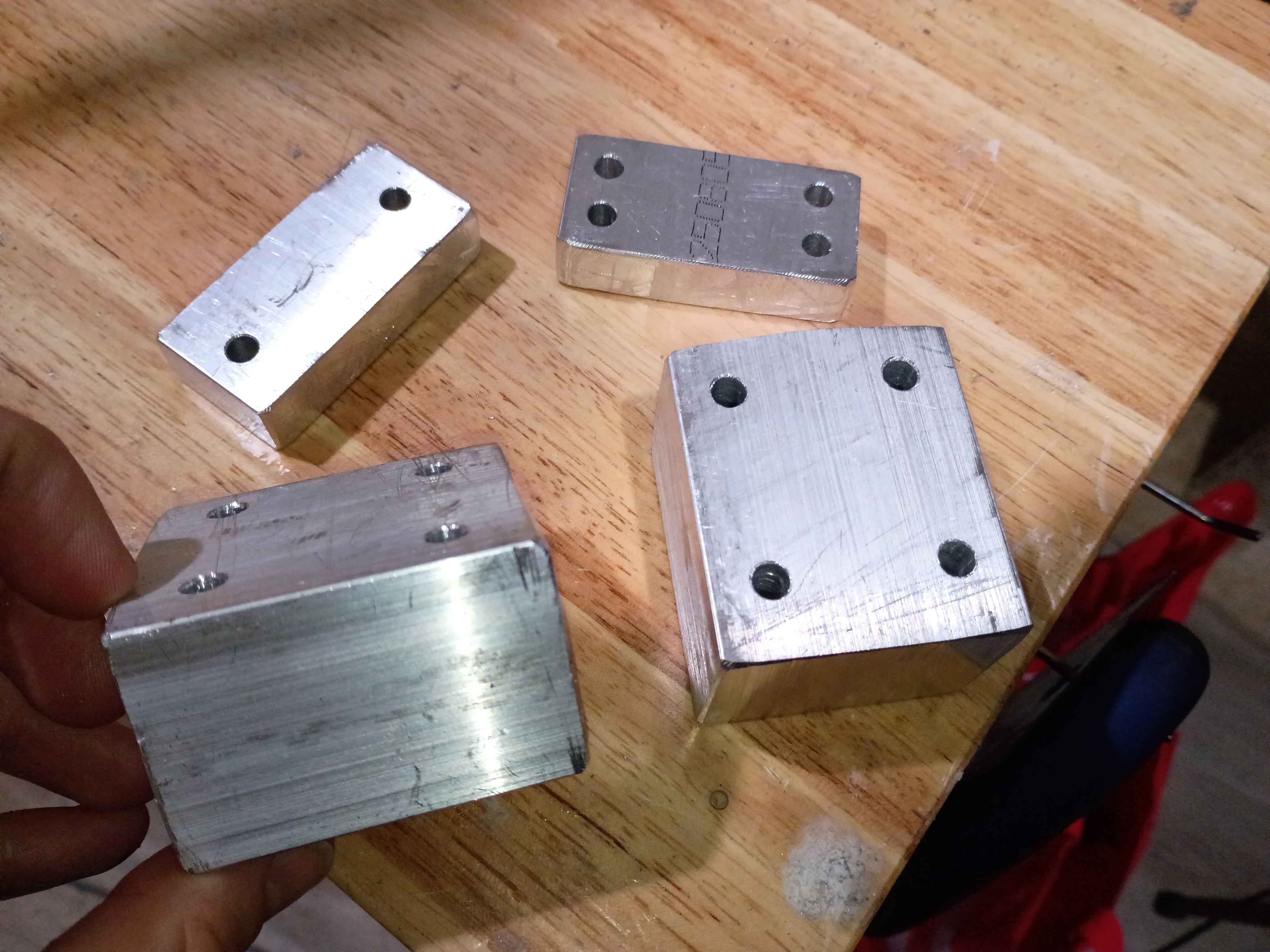
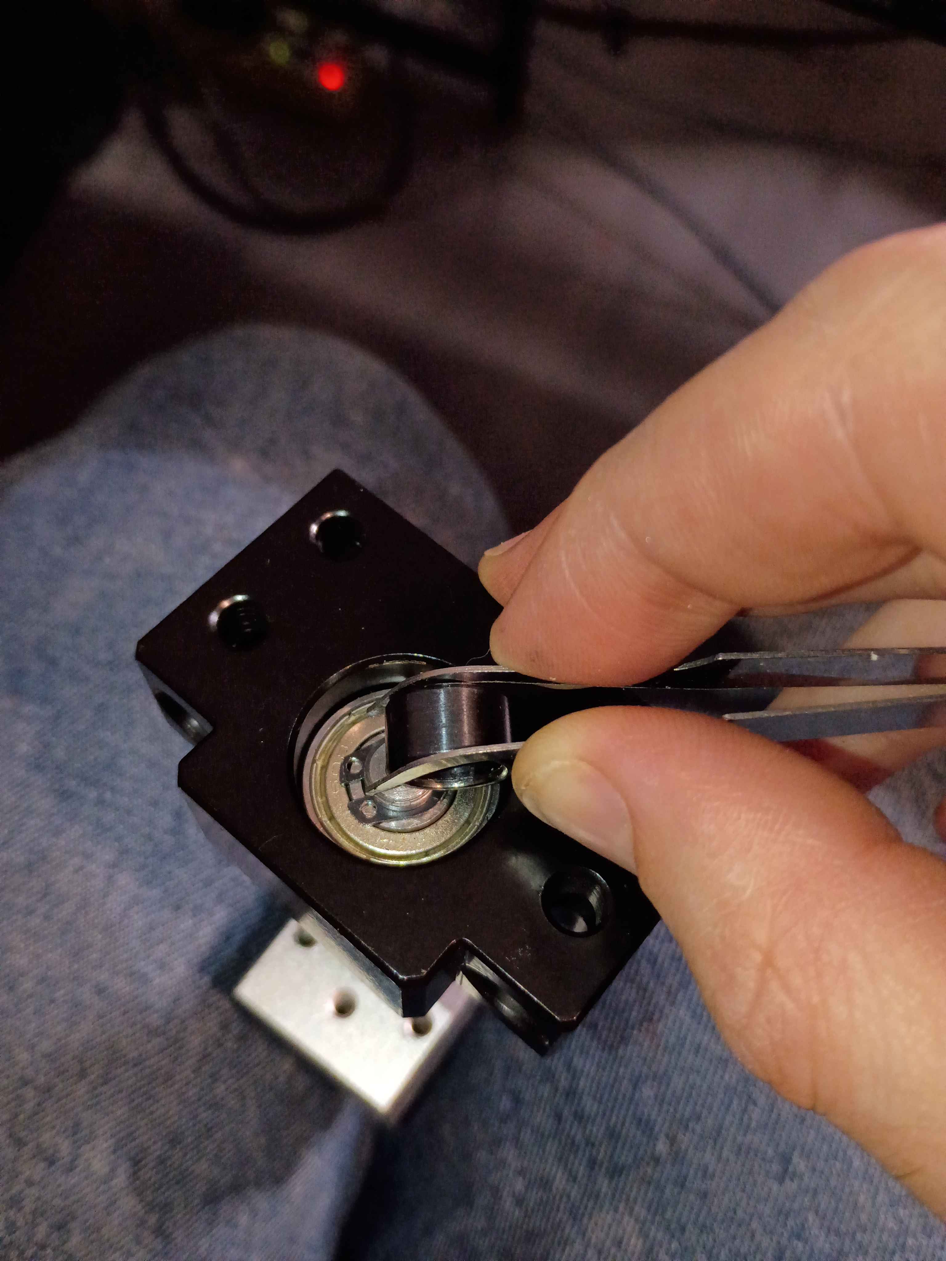
Cut, filed, and drilled spacer blocks for the z-axis motion system clearance. Discovered that for making straight hacksaw cuts through thick material, you can cut a trace around the entire perimeter first, and that will help guide the saw through straight. Also discovered that you can install the circlips using those IC tweezers to grab the holes and a small (ideally round) object that you can slide in between to spread the circlip open; it worked surprisingly well. Also observed that the shop-vac made super quick work of the aluminum chips and oil-file dust - way better than wiping or sweeping. 
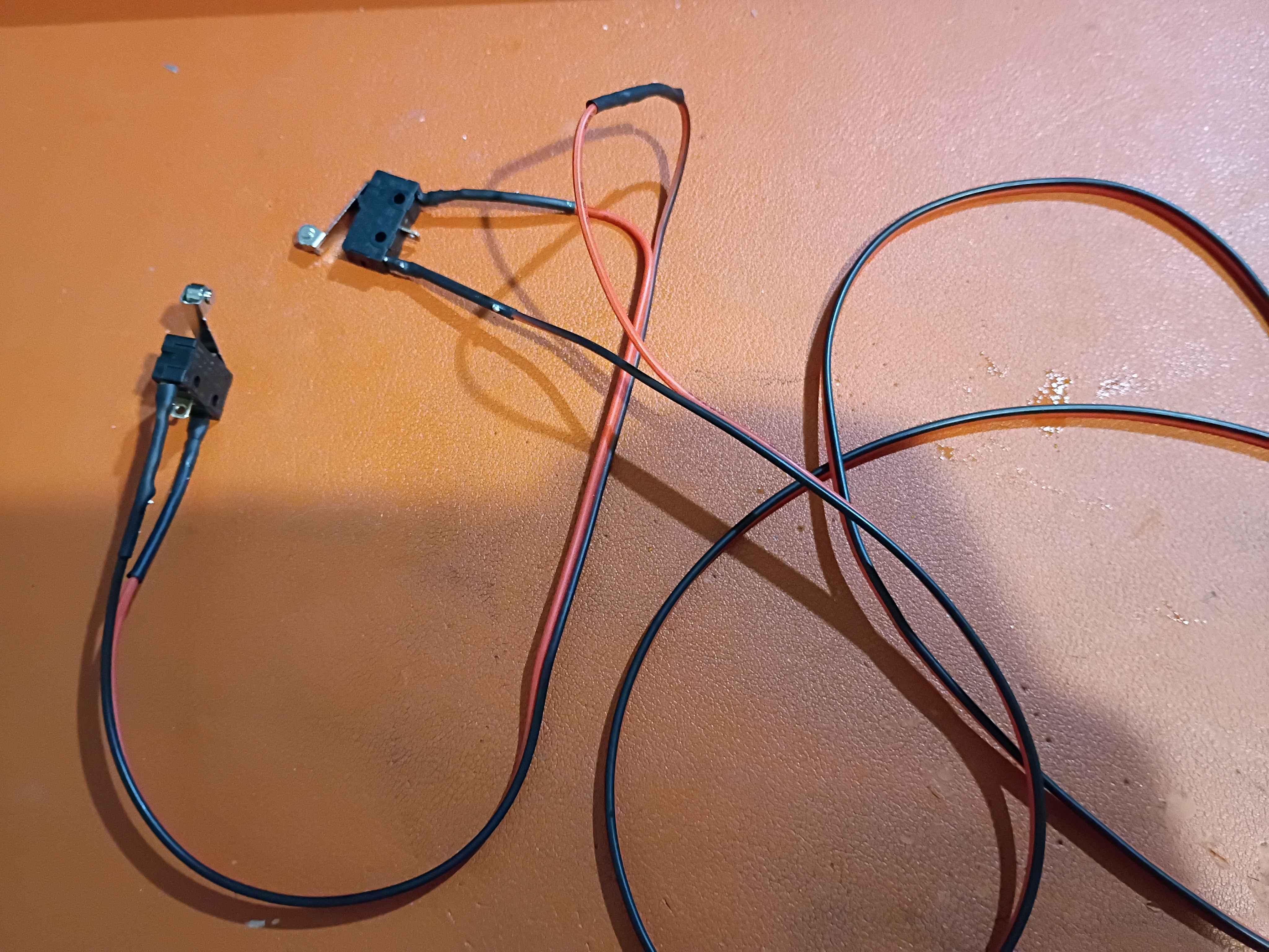
Installed 2x corrected 00001-001B along with the limit switches. Should have probably cut a longer connecting wire between them, but this will do for now. 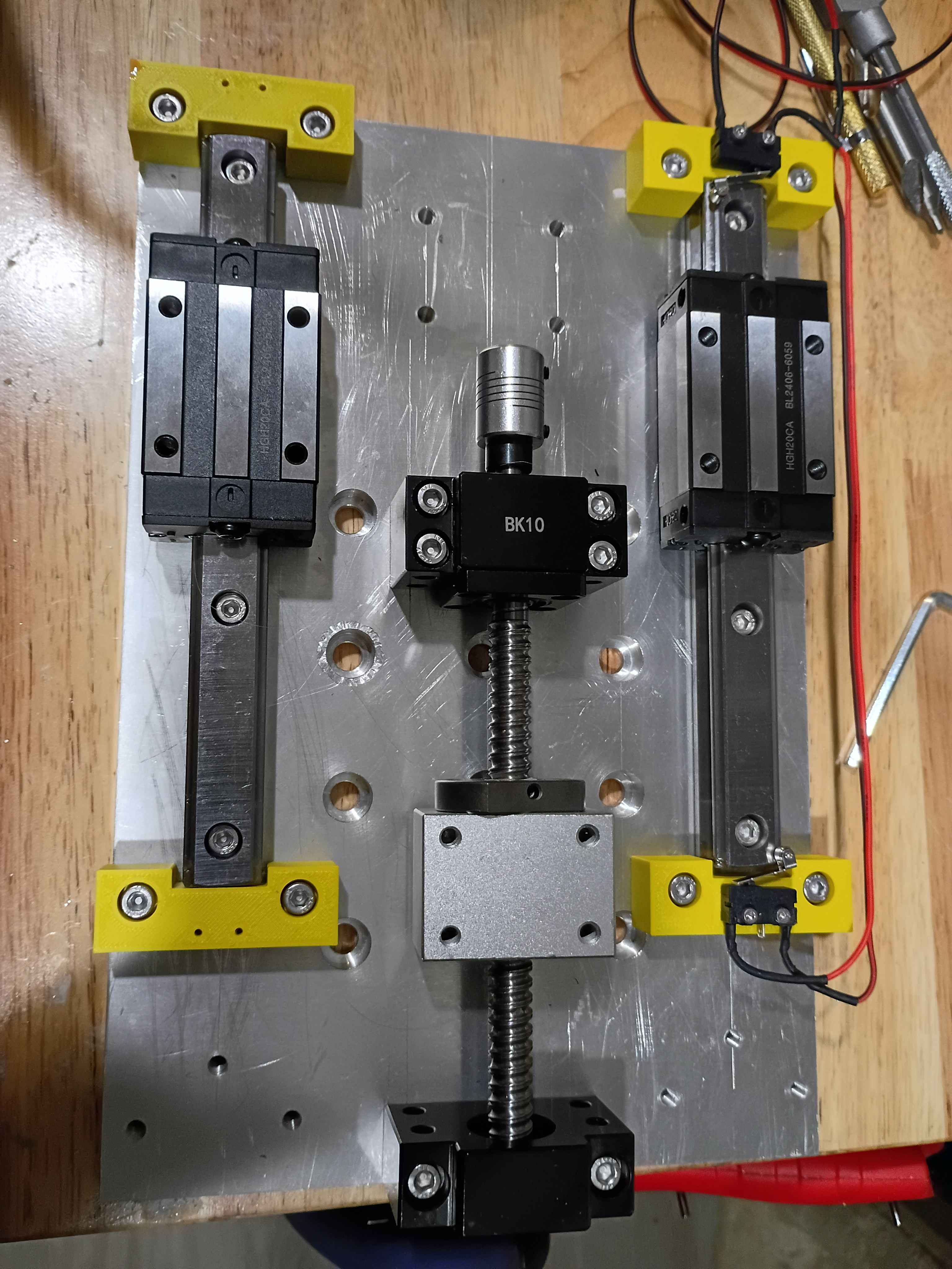
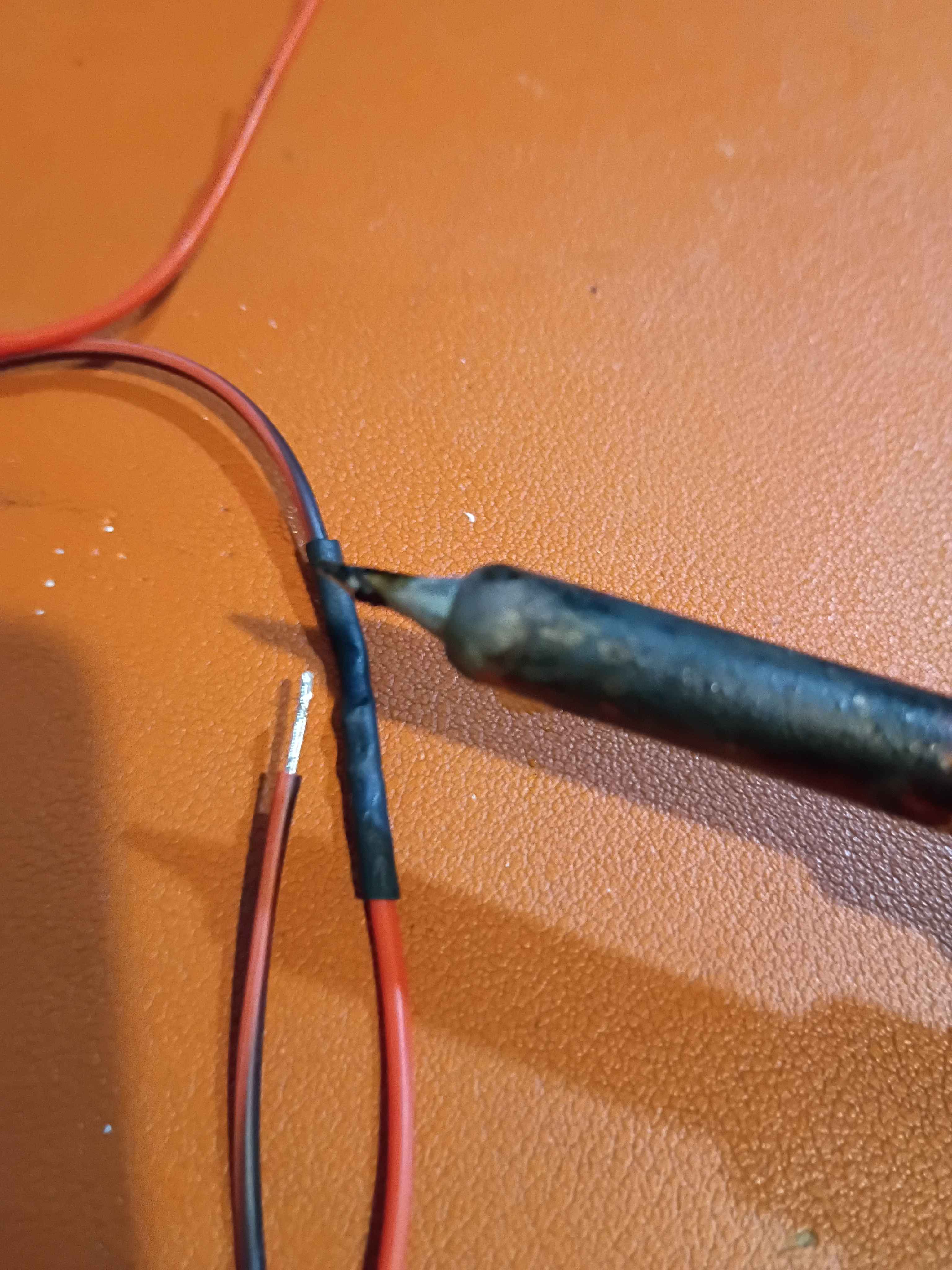
Printed 4x endstop blocks and attached those linear motion components. Realized I need to slightly adjust the limit switch mount holes, so the 00001-011B was redesigned and is being reprinted overnight. Soldered up the series NC limit switches. Realized that with the new narrower heat shrink tubing, the side of the soldering iron is sufficient to shrink the tubing without burning anything, whereas my normal approach of the heat gun for the thicker tubing sometimes causes nearby plastic, especially 3D-printed plastics, to melt. 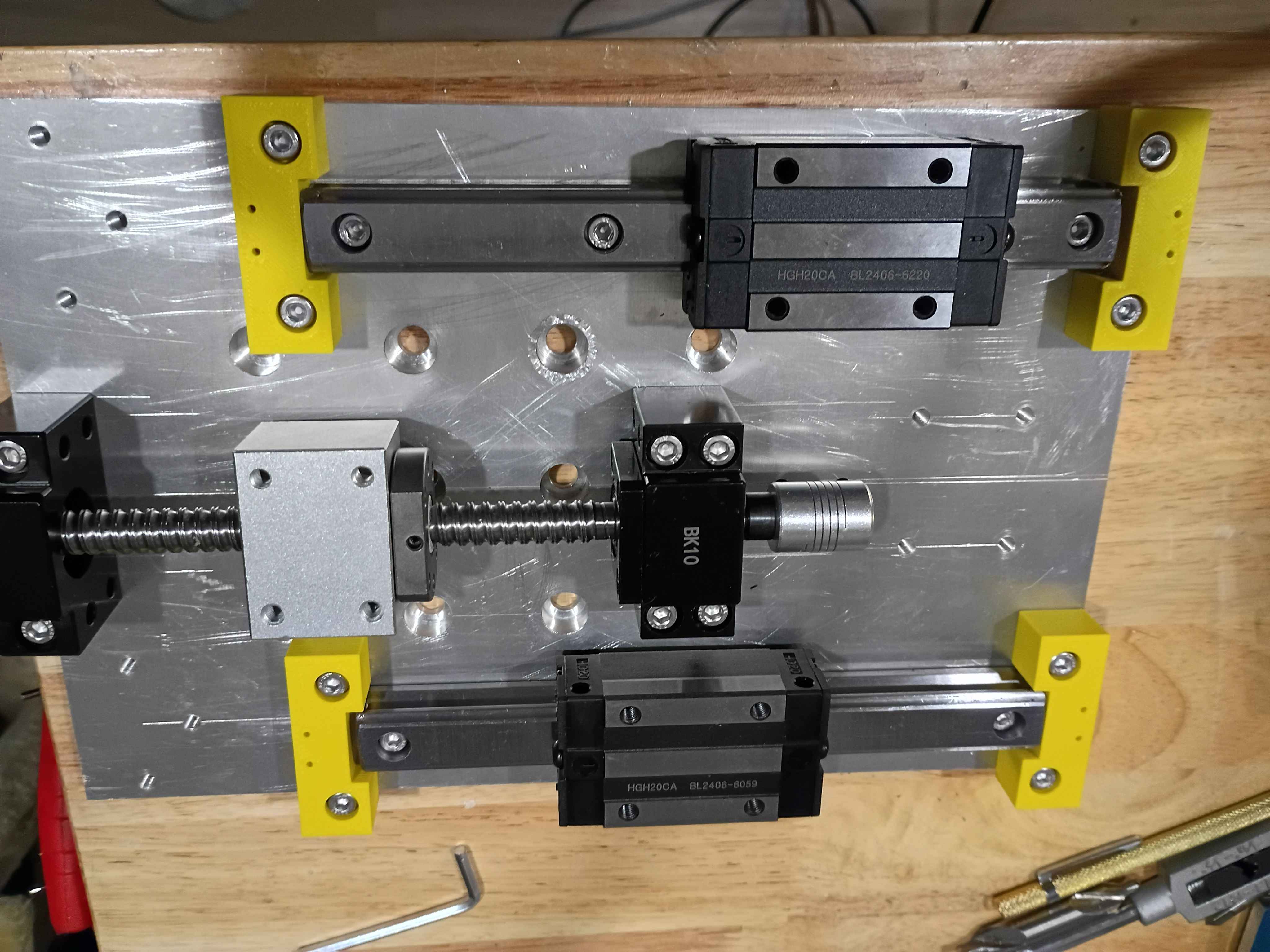
Revised the 00001-011A endstop blocks to handle better tolerance variation in the linear rail ends, as well as having mount points for limit switches. These are being printed overnight. Also determined the required spacer thicknesses for the z-axis motion components, and purchased them on McMaster. 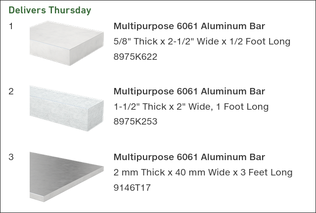
Designed and printed z-axis linear rail carriage blocks. 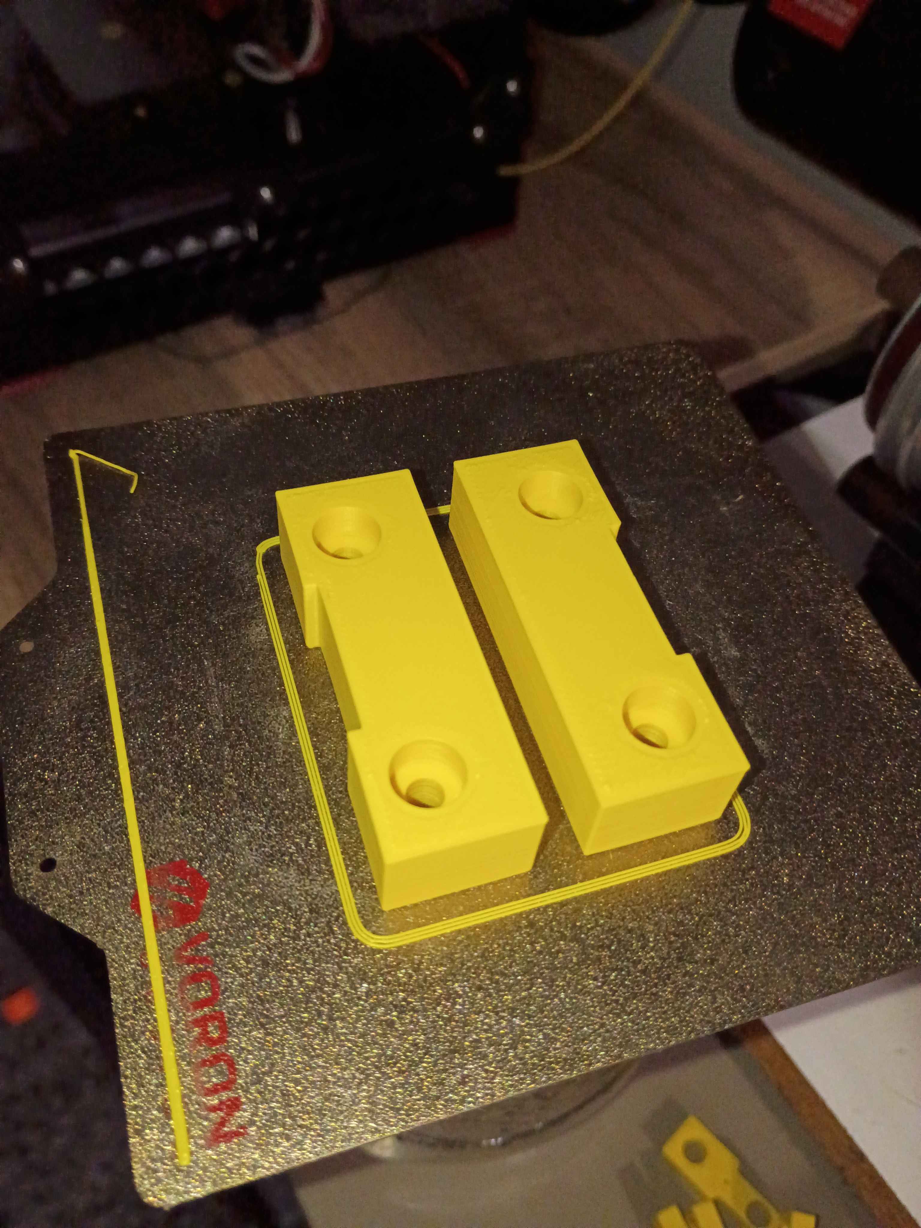
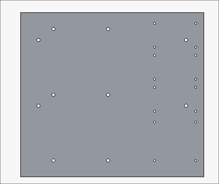
Laid out Z-direction motion components and marked out the hole locations very accurately (hopefully). Drilled and tapped all the mounting points for the rails, the ballscrew supports, and the stepper motor mount. Also drilled and tapped holes for a slightly longer set of rails (for upgradability) and also end stop blocks that can hopefully be 3D printed and would serve as mount points for the limit switches but also prevent the carriages from sliding off the rails in any direction, especially down due to gravity. 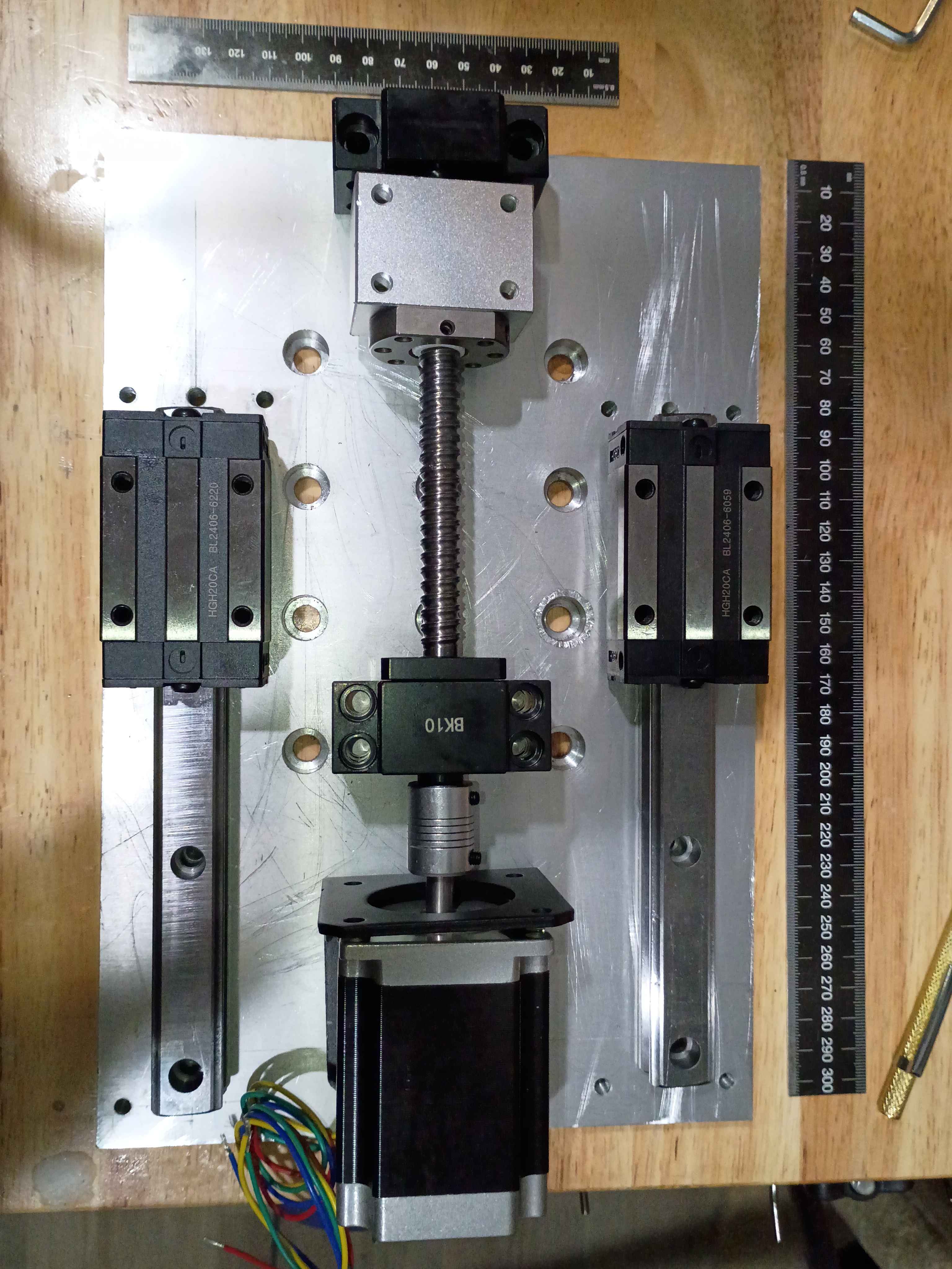
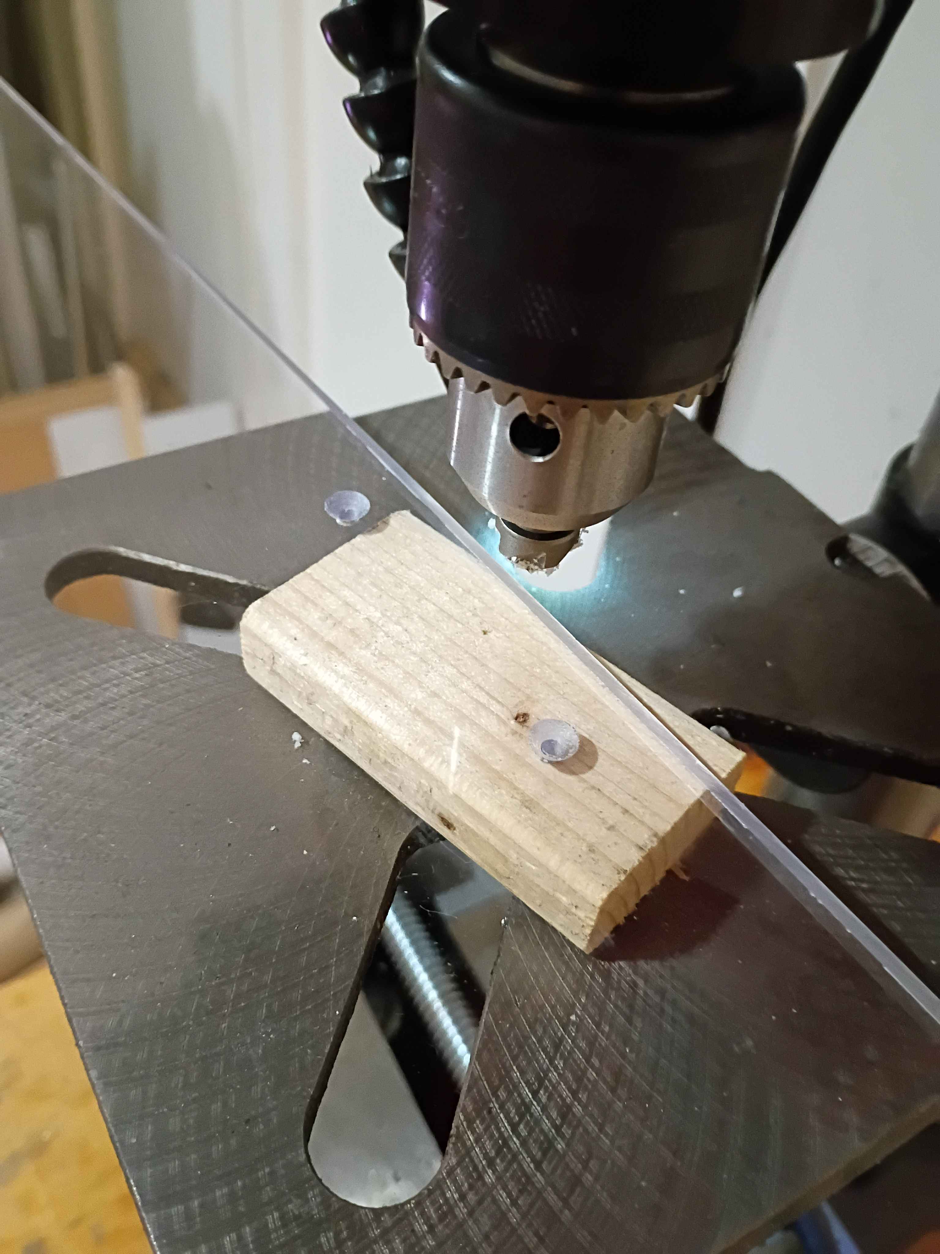
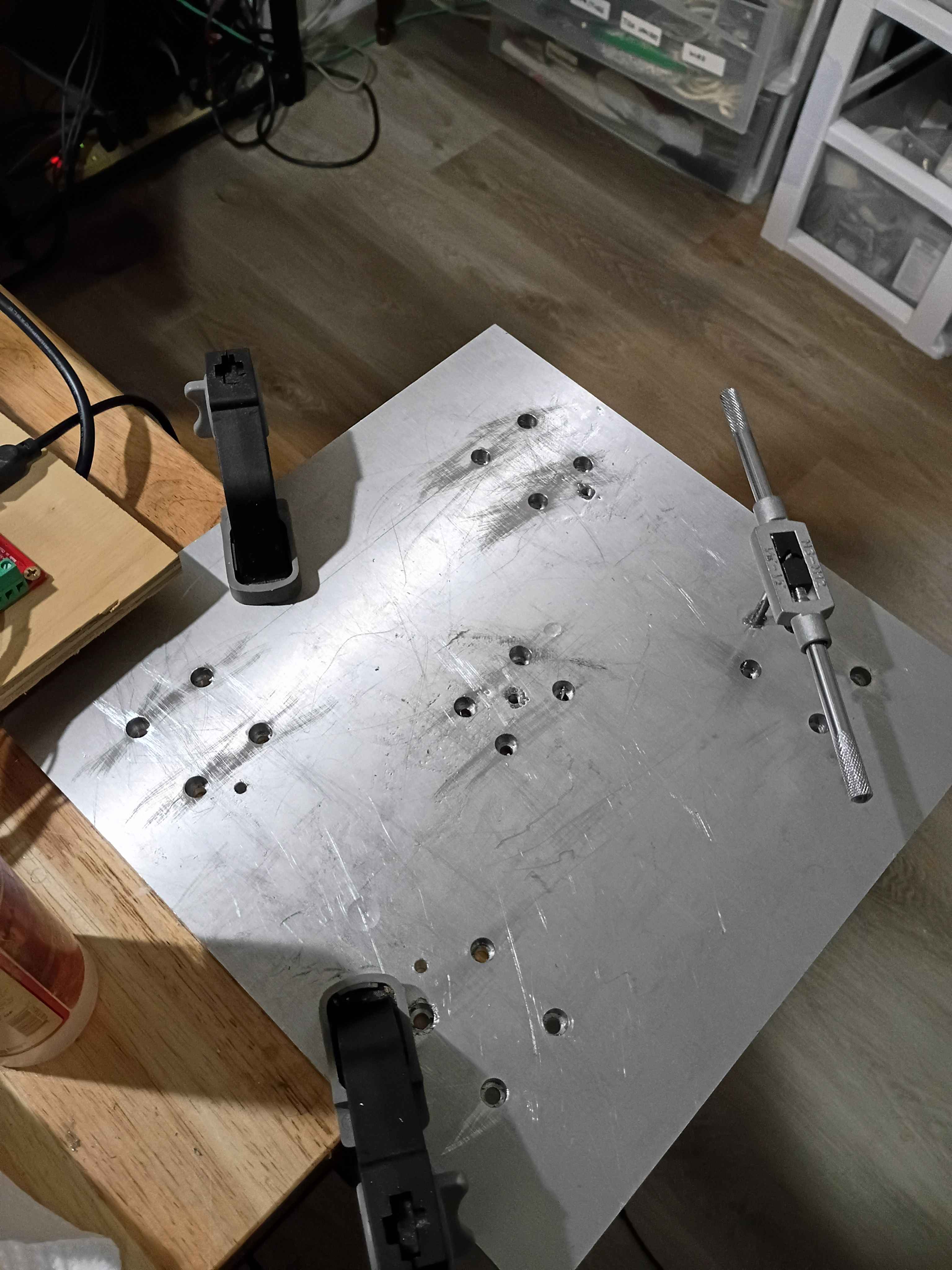
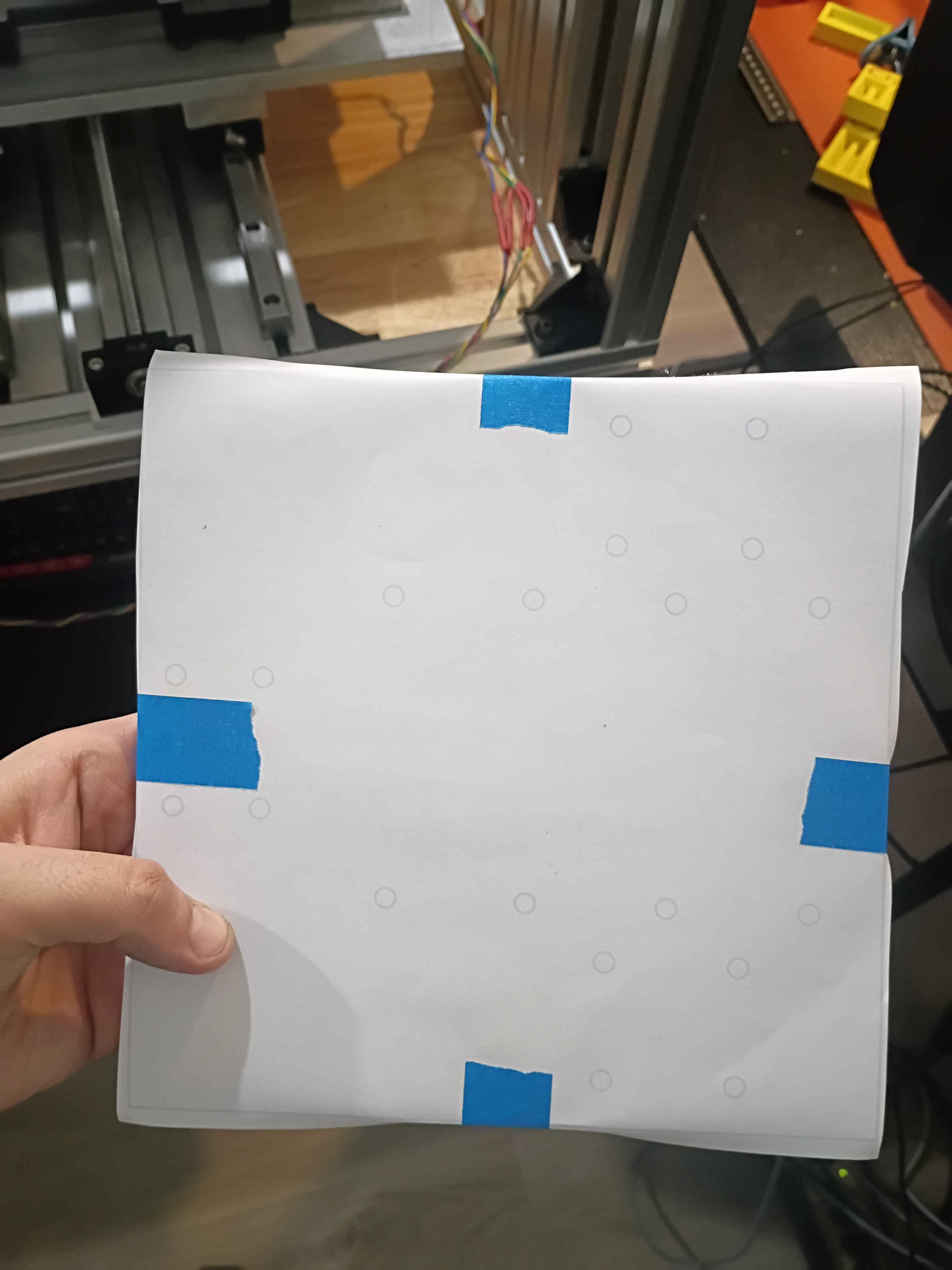
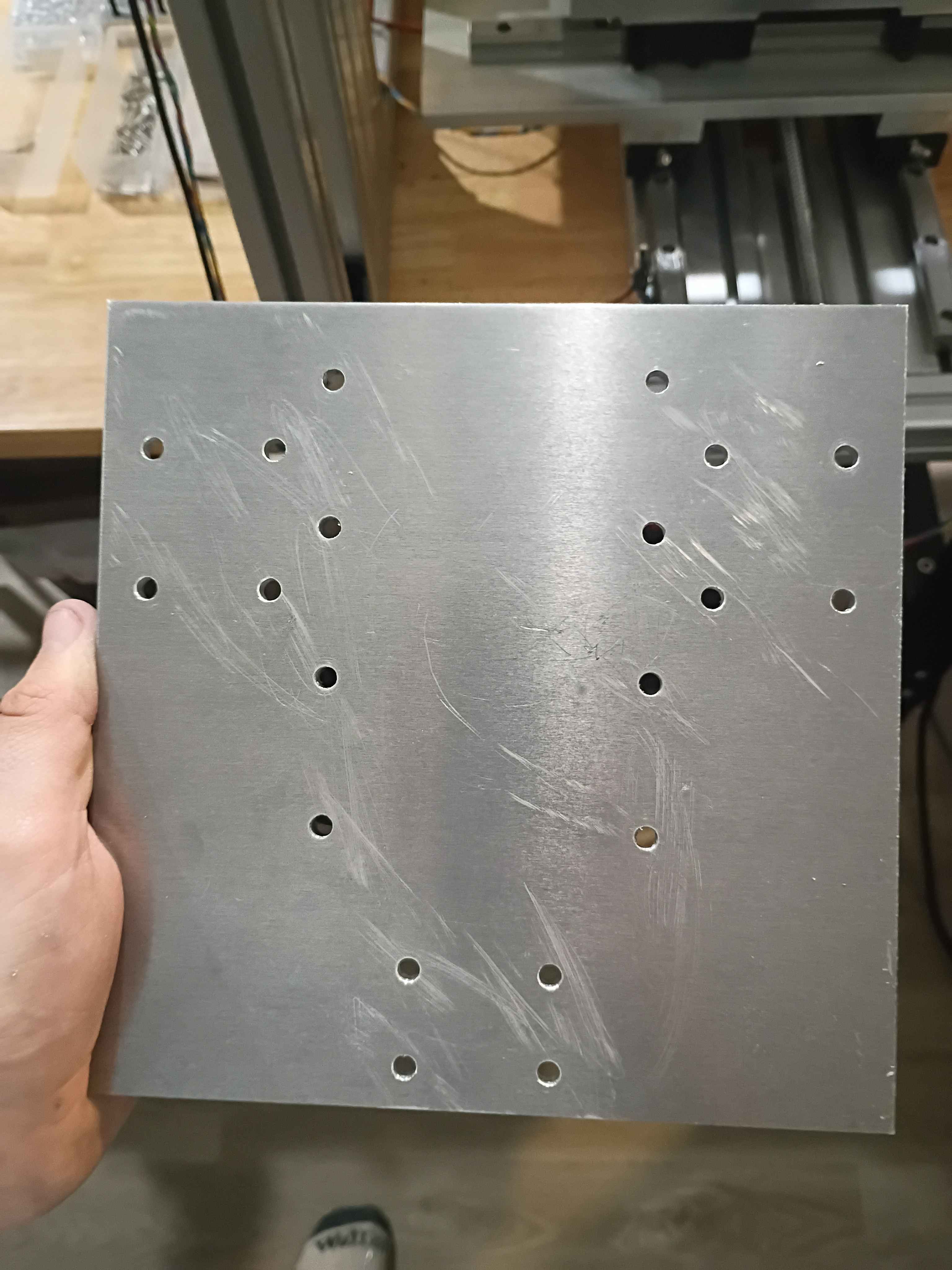
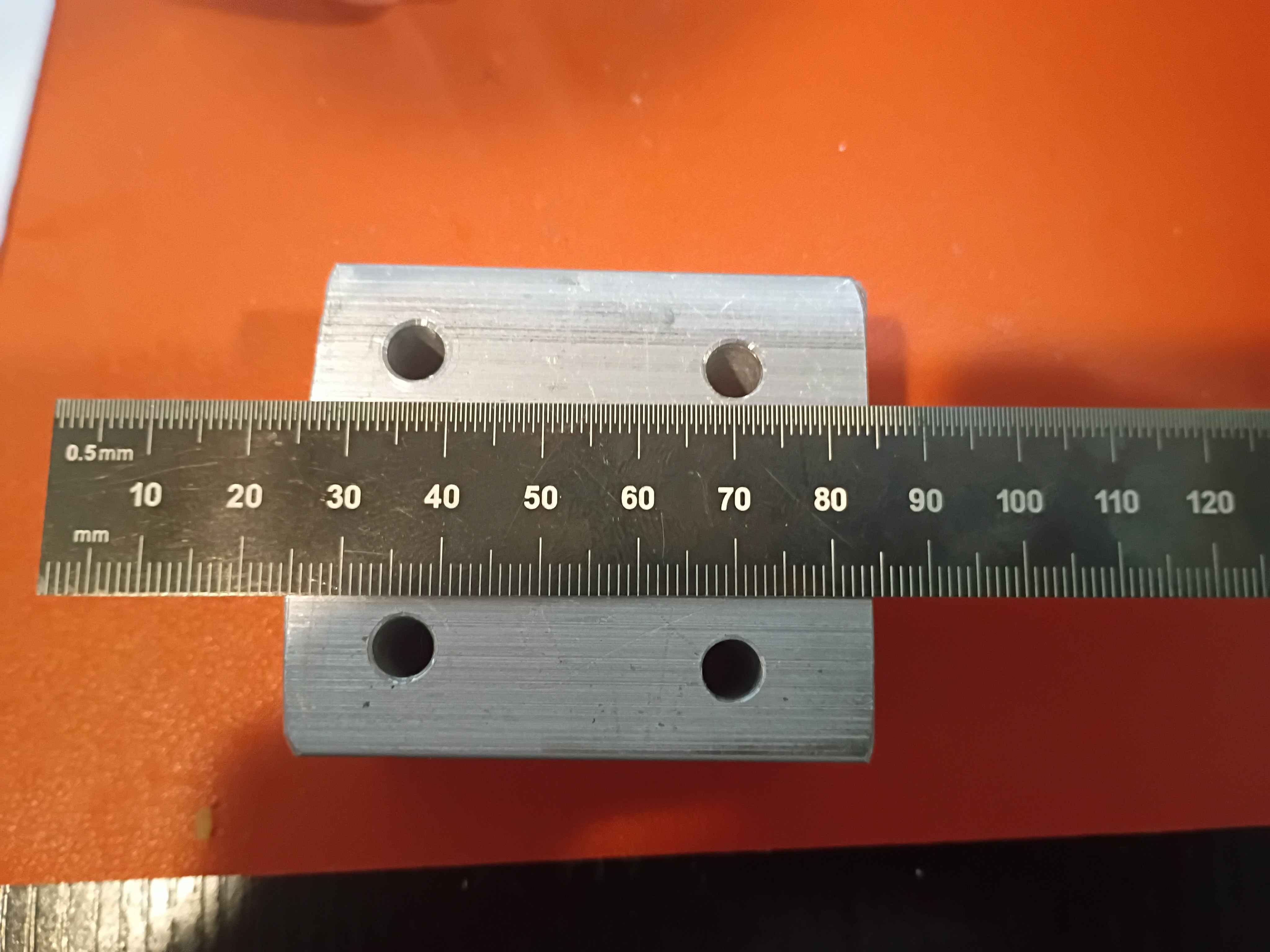
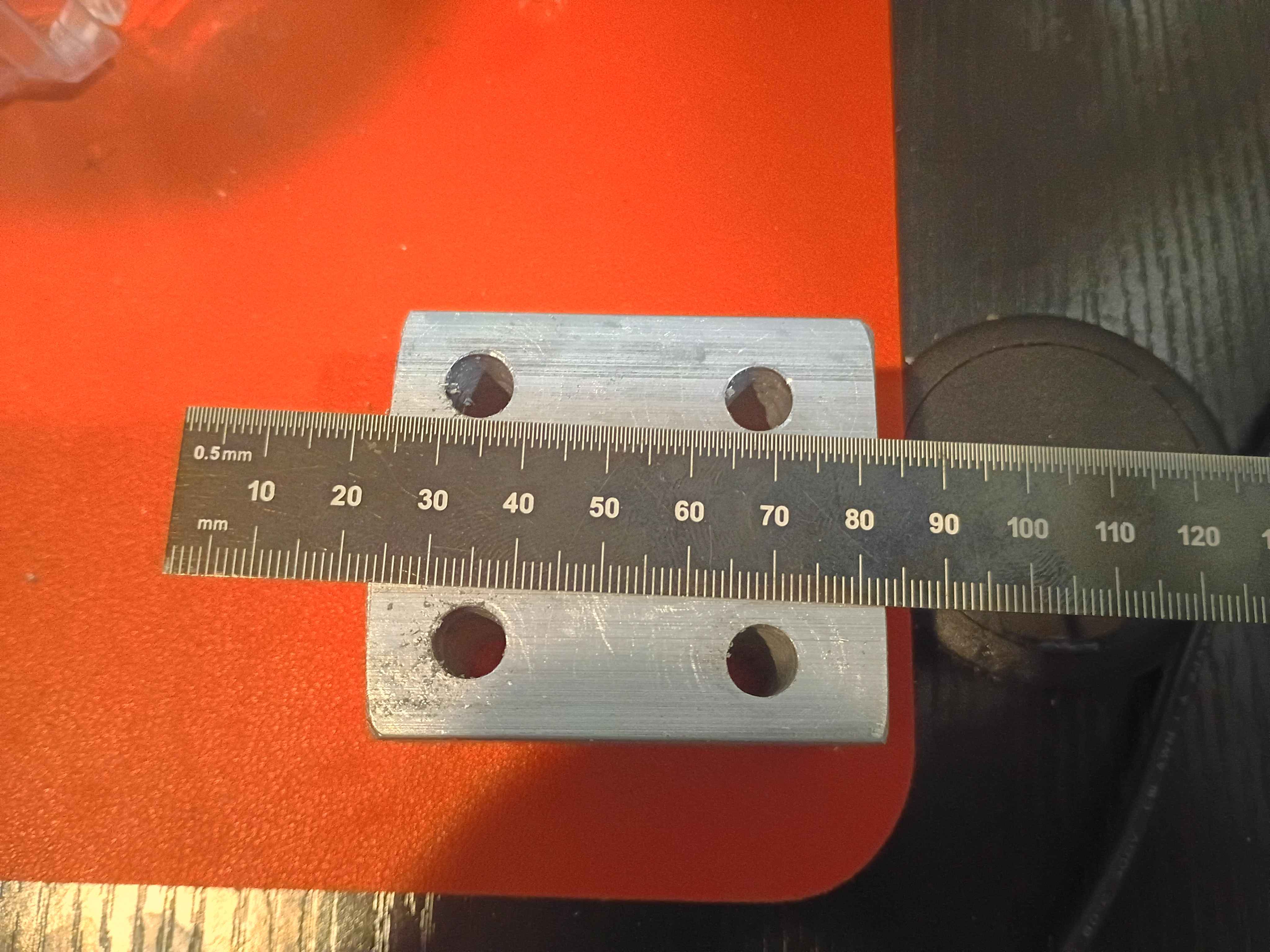
Marked, drilled, counterbored, deburred, and tapped the Z-motion mounting plate. Unfortunately I accidentally did tapped for M6 screws instead of M5, which are the largest that fit in the linear rail holes, so I will need to drill and tap another array of these outer holes, slightly offset from where I made them. Also, learned that you can depress the drill press and counterbore bit on the edge of the part to set the end stop depth appropriately, see last picture. 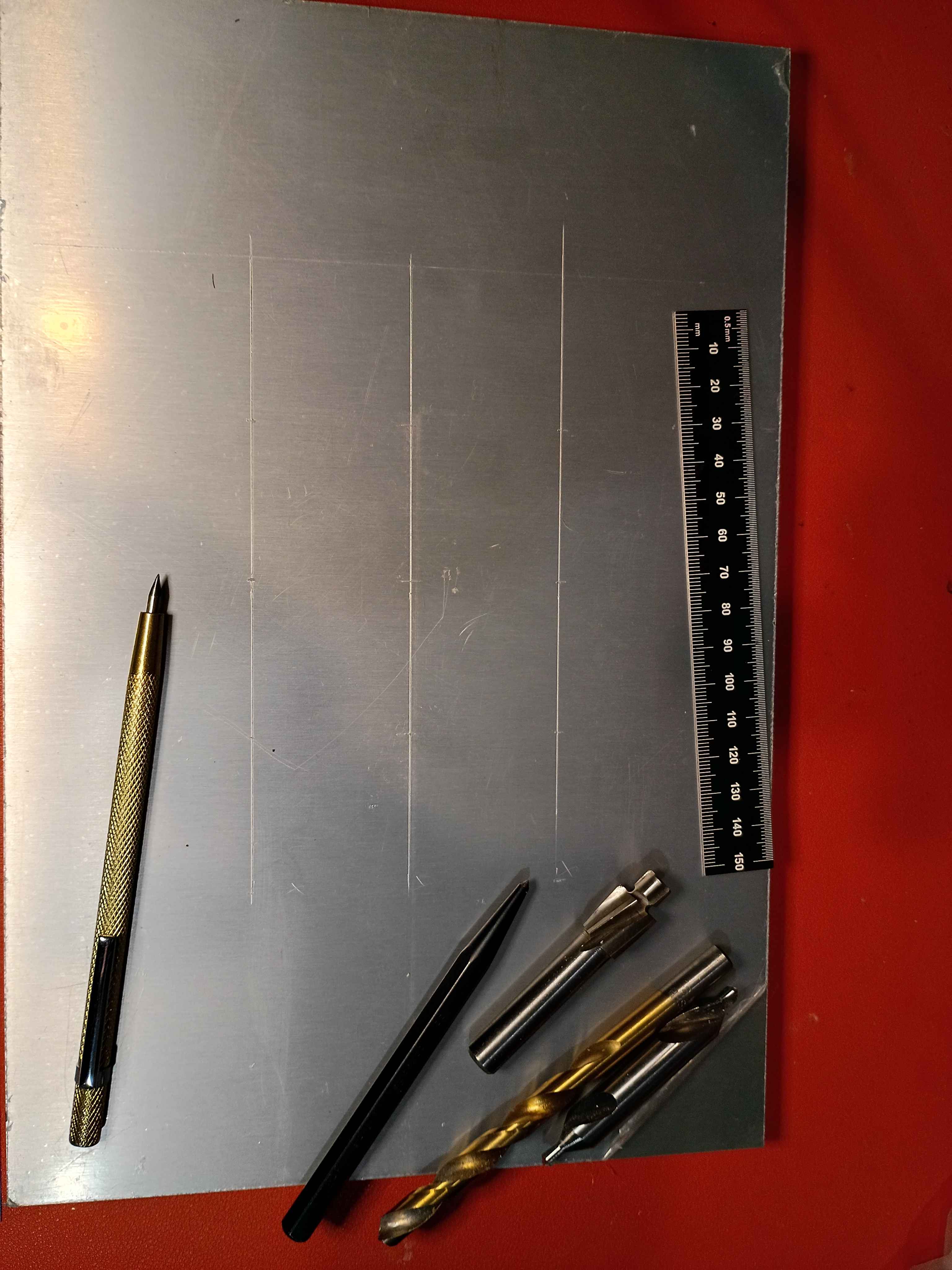
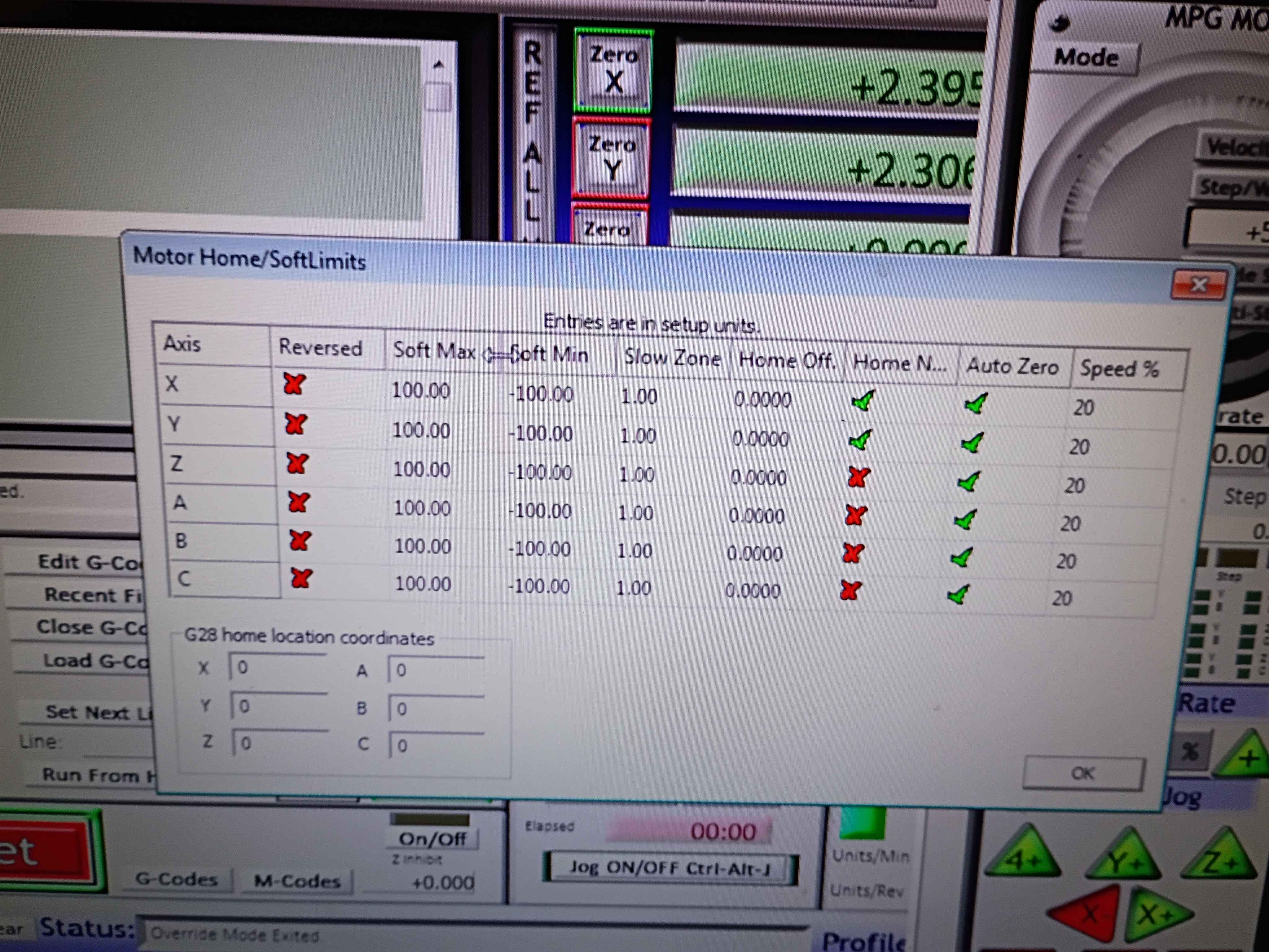
soldered and wired both y-axis limit switches in series NC between GND and the input pin. Got the Mach3 CNC software to recognize and work for both the X- and Y-direction for limit stopping and homing. The below images show the settings which were not easy to determine. See video of limit switches working. I should eventually redesign the x-limit switch mounts to get some more range of motion. Currently there is only like 3.5 inches in each direction. For future reference, Tab opens the jog menu in Mach3, the Settings tab (Alt+6) lets you override the limits to get unstuck, and the Diagnostic (Alt+7) tab shows pin states among other things. Also port 3 is the input pin port on the RNRMotion DLL and board. 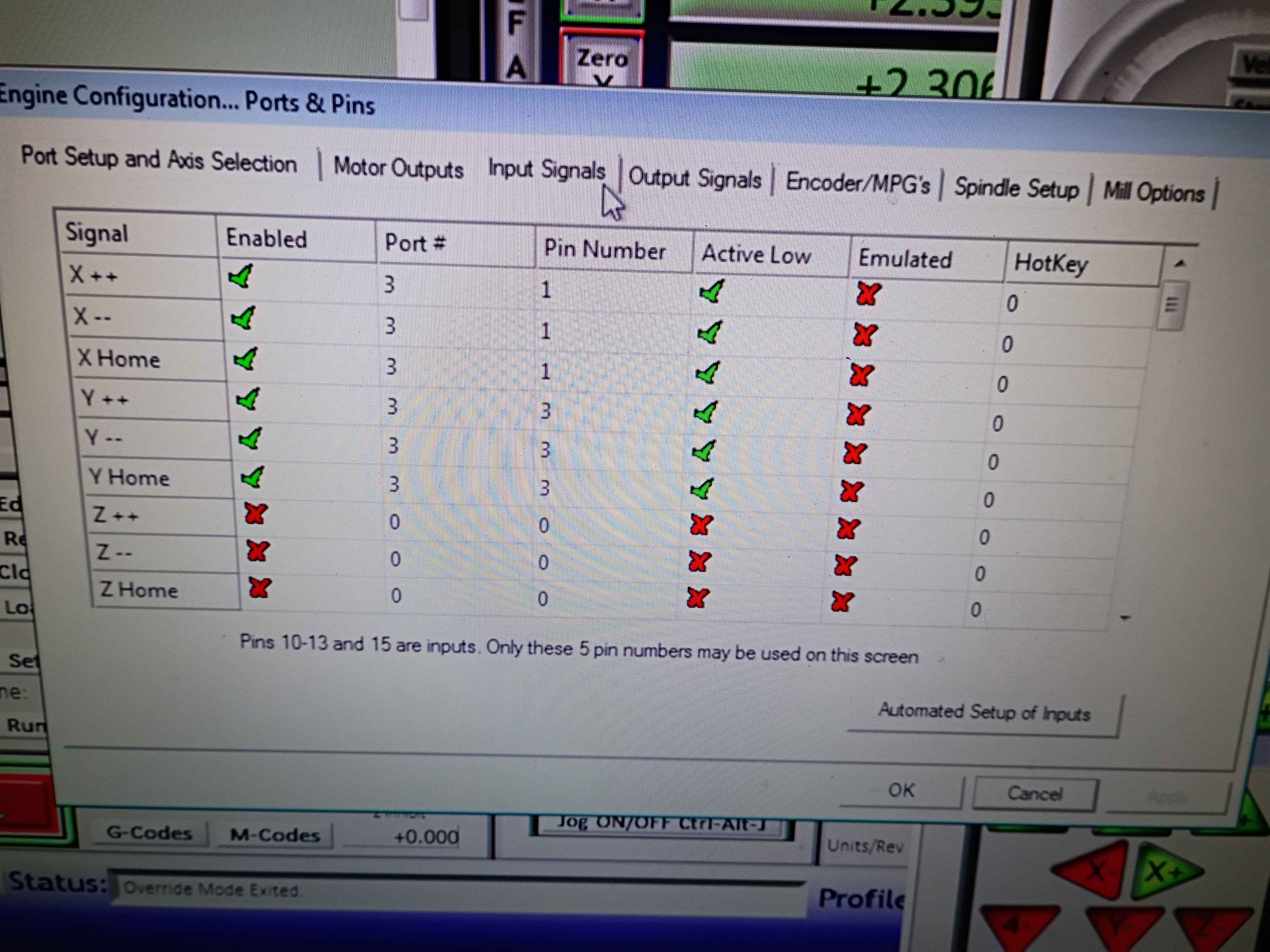
Redesigned and printed 00001-010A. Installed limit switches (unwired), and used friction and hot glue to install both side brackets onto the ball screw support blocks. 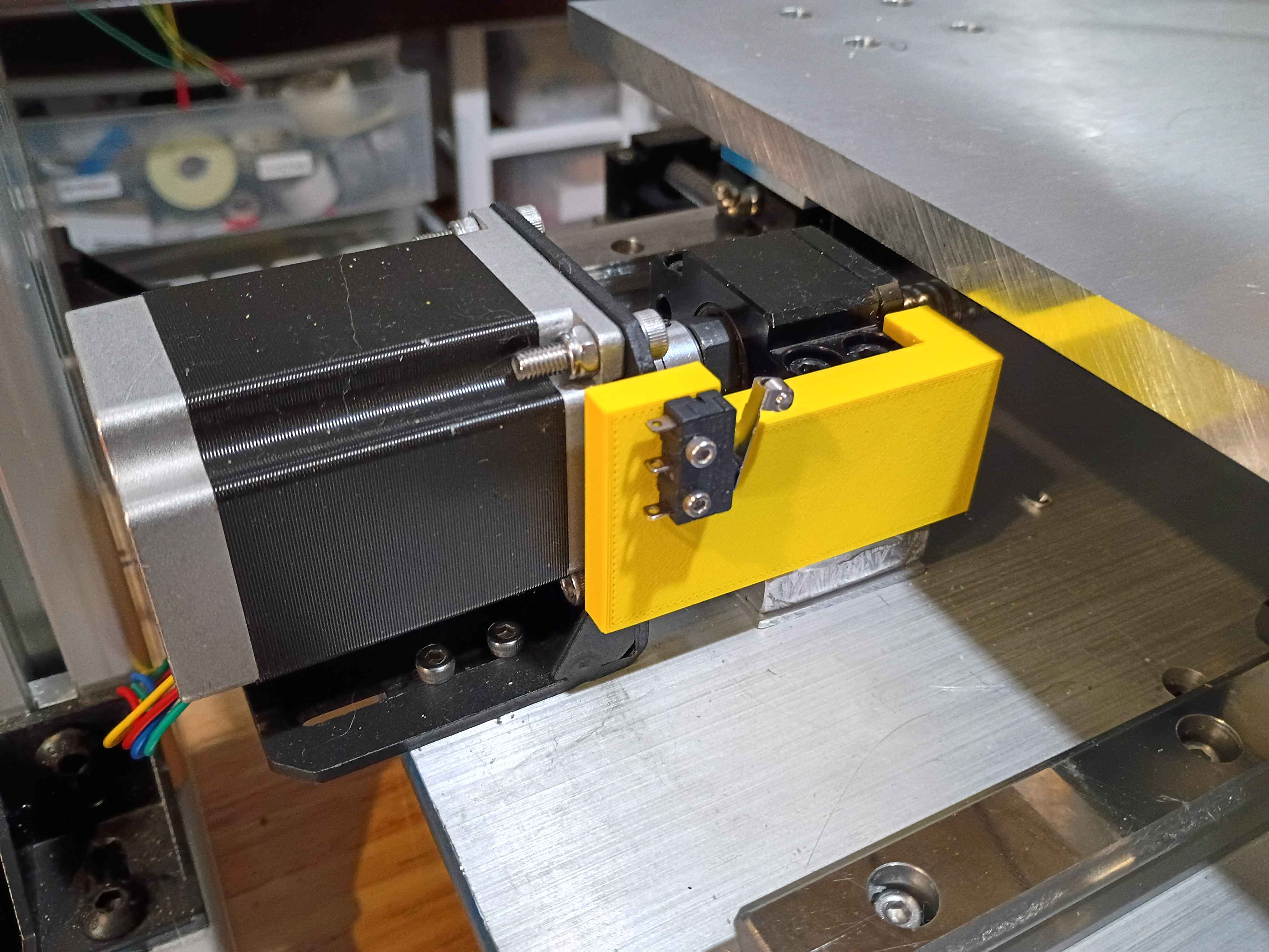
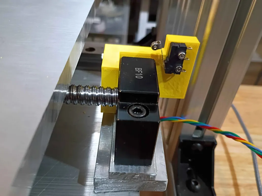
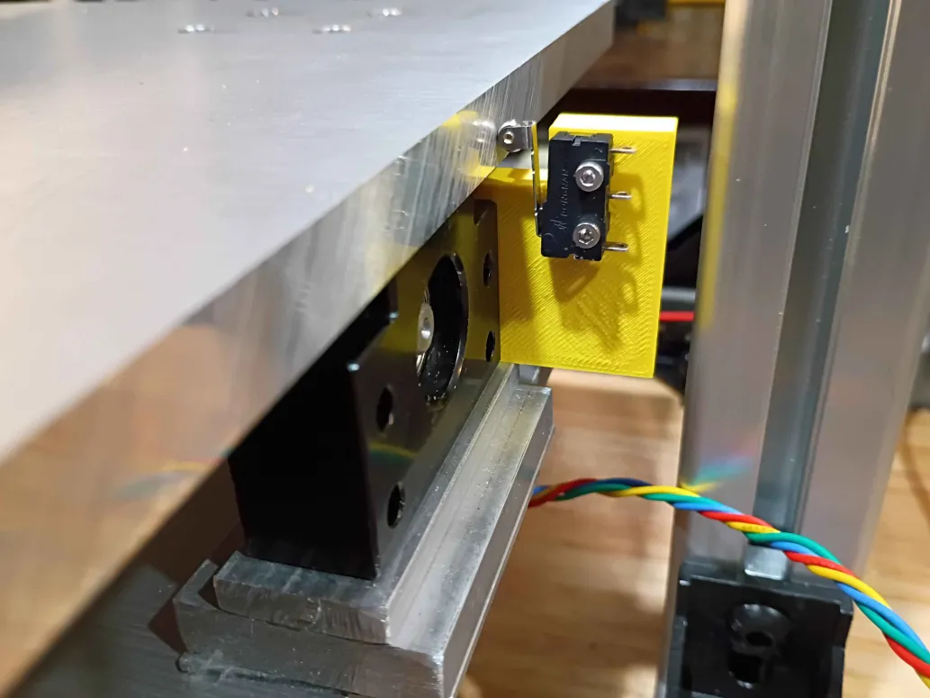
Printed the 00001-009 and installed limit switch successfully into position (unwired currently). Fits perfectly. Designed and printed the opposing 00001-010 part. 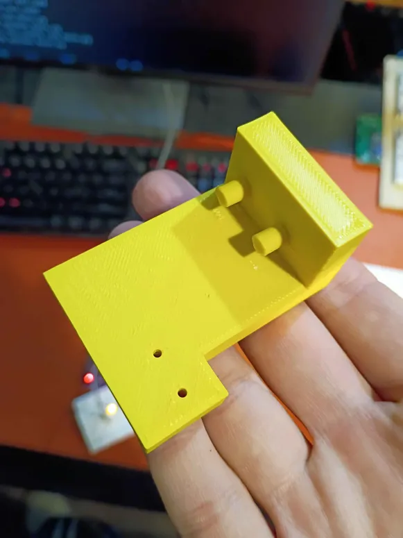
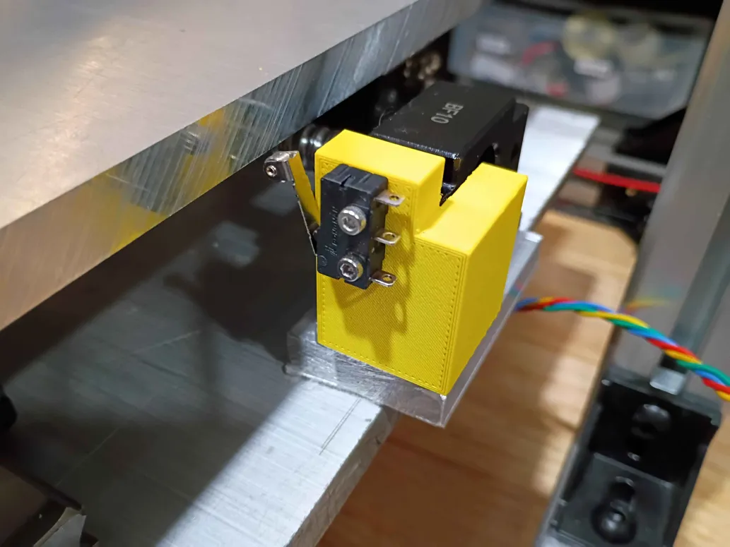
Redesigned limit switch bracket with cutaway for gantry motion. Printed in a different orientation to enable stronger pegs. Will be installed in the opposite orientation shown in Figure 2 below. Currently another design iteration is being printed that maximizes the range of motion along this axis. Due to the asymmetry on the ballscrew supports, a unique but similar part will be required on the opposing side. 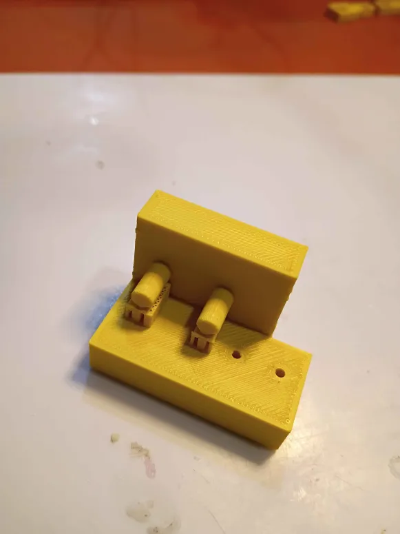
Designed and printed first iteration of y-axis limit switch brackets (00001-009). Found 3 geometric characteristics that needed to be revised, and submitted another overnight print. 
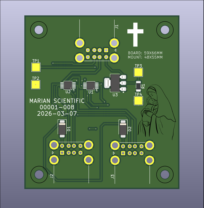
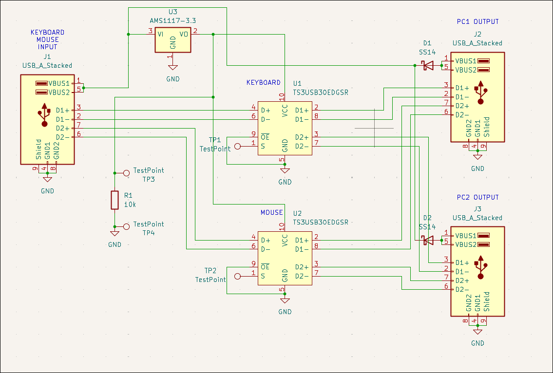
Designed USB mouse & keyboard splitter board (00001-008) for the CNC PC control. Likely will not purchase. 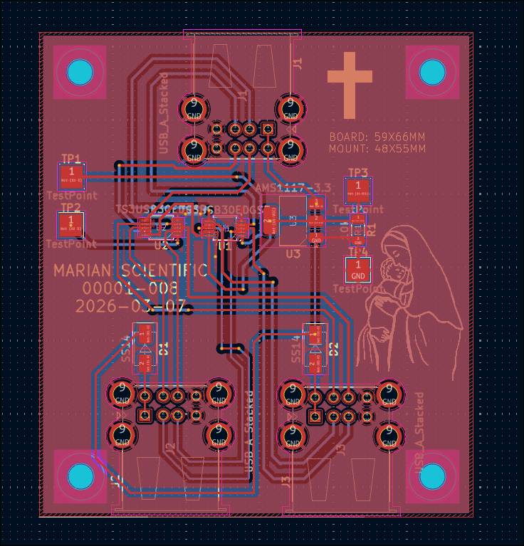
Redrilled and assembled Y motion to eliminate binding. Added Y motion electronics and tested the control software. 
Cut, drilled and installed shims under the gantry plate. Also reversed the 2 upper mounting screws on the y-axis stepper. Altogether that gives roughly 110mm of motion. I will have to drill out some of the holes a bit wider and possibly straighten the rails because currently there is some binding in the Y-direction motion. 
Installed gantry plate successfully, but apparently there is insufficient clearance with the ballscrew support blocks for more than 1 inch of motion in the Y-direction. I will need an additional 2mm shim on all carriages and possible 3mm on the ballscrew follower nut. 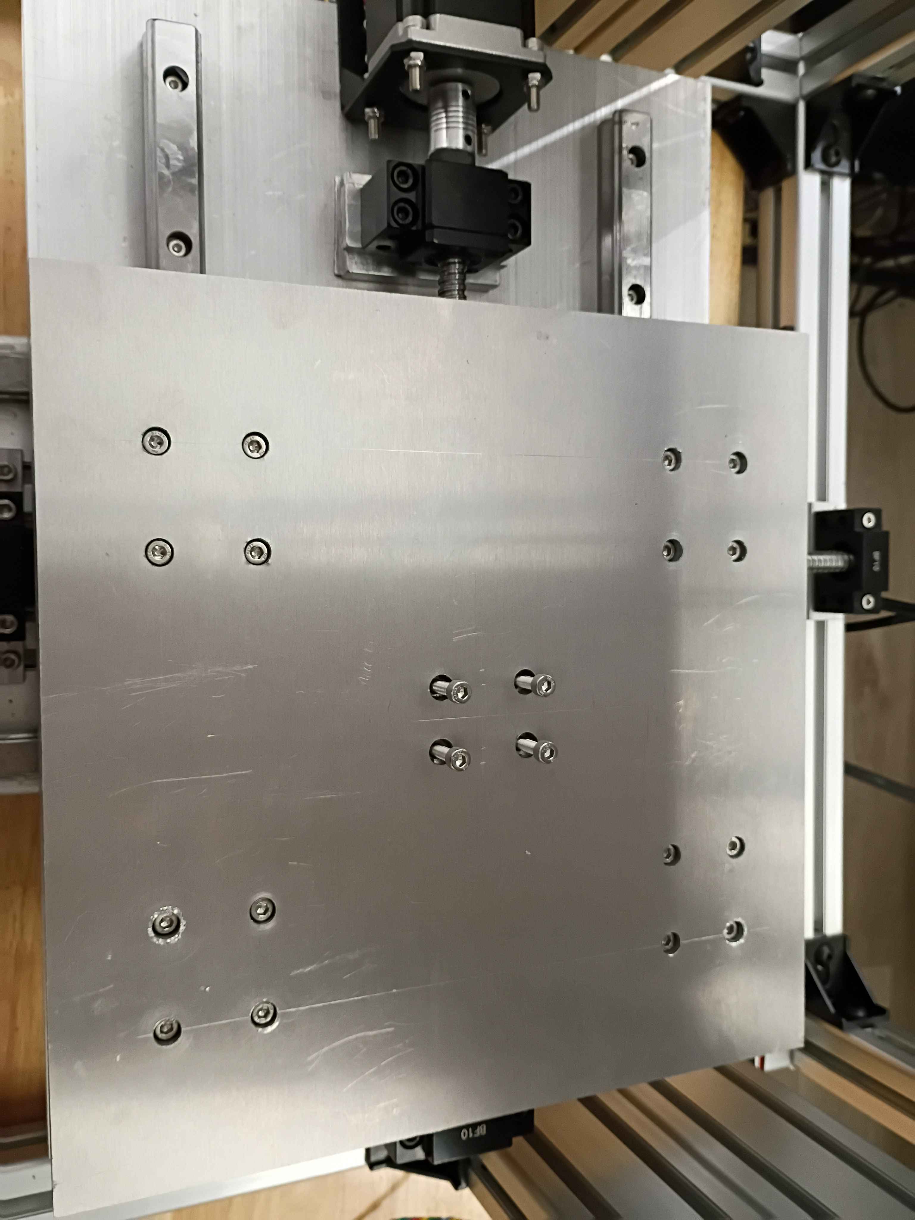
Cut, filed, drilled, and deburred 4x linear rail carriage mount spacers for the y-axis motion system. Ordered the corresponding length screws to mount the gantry plate.
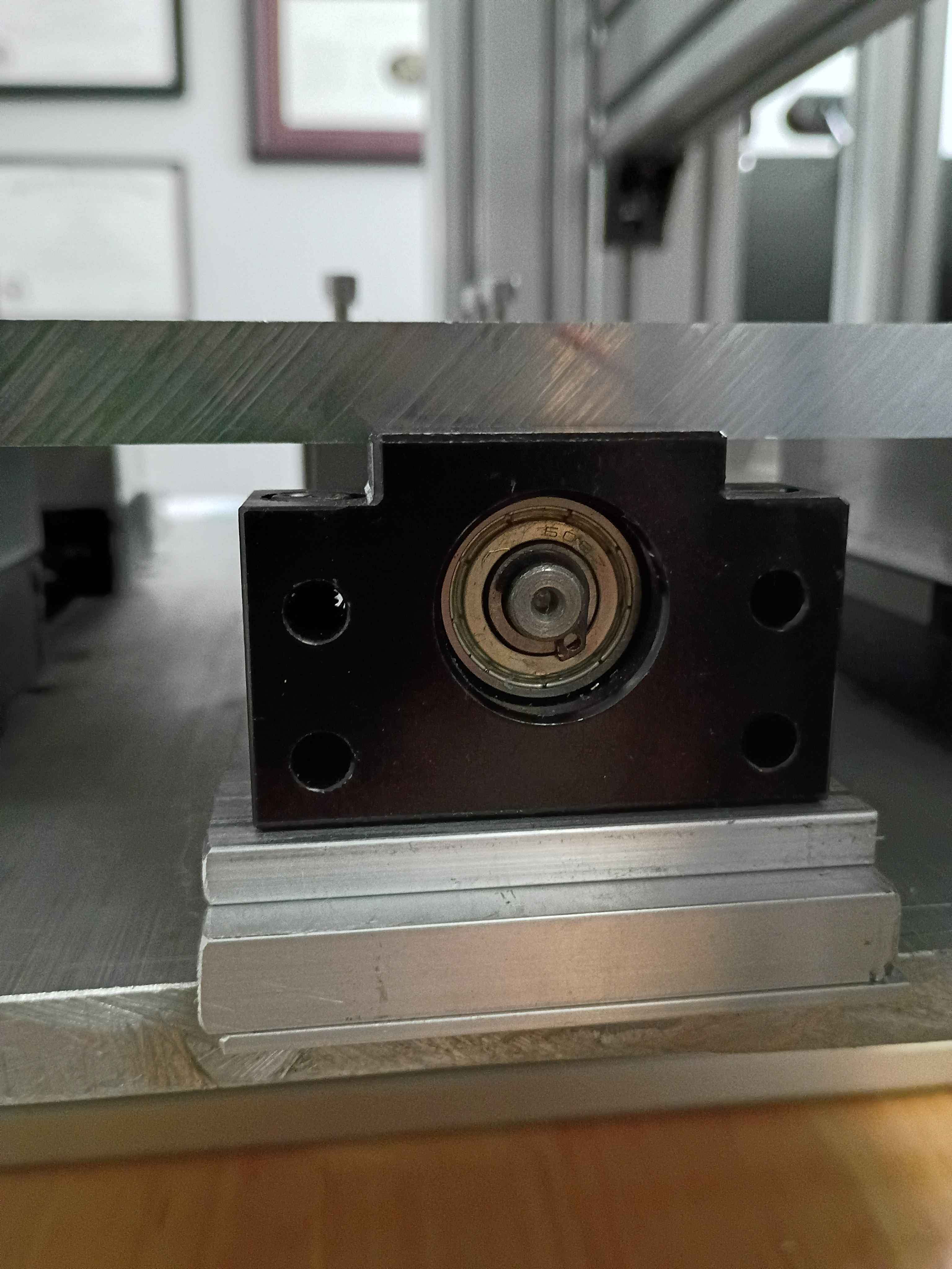
Bolted down Y-axis ballscrew supports, installed lubrication nipples, vacuumed the entire assembly, and lubricated the rails and screw. 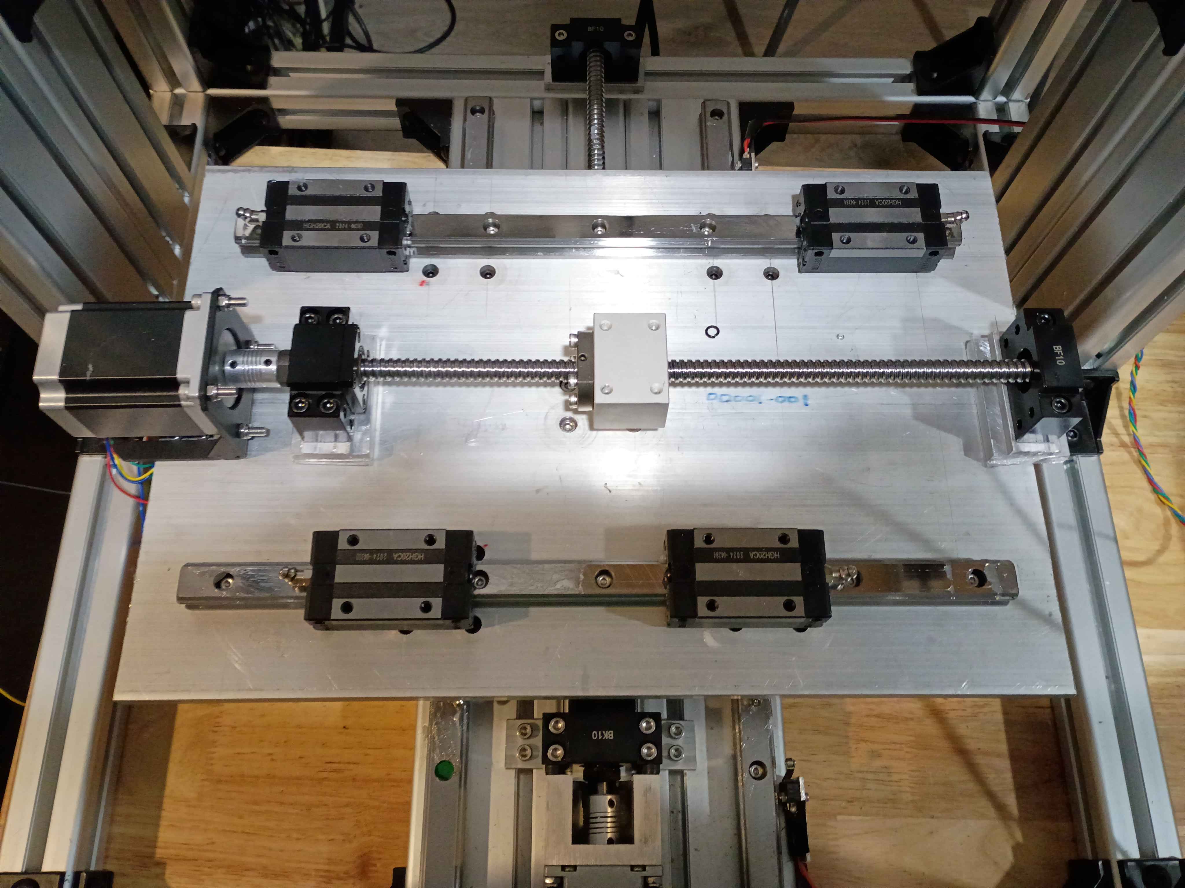
Installed ballscrew nut follower onto Y ballscrew. Determined height of linear rail carriage spacers (25mm ~ 1in) and ordered some aluminum stock for that purpose. Also printed templates for the clearance hole patterns. To simplify this process going forward, I spent some time configuring my network printers.
Cut, filed, and drilled clearance holes in some spacers for the ball screw support blocks for the XY gantry motion. Took a while to saw because my hacksaw blade is getting quite dull. Used Inkscape, my printer, and a gluestick for the first time in this application to actually mark out the drill locations, which worked swimmingly. I do need longer M5 bolts to mount these, however. 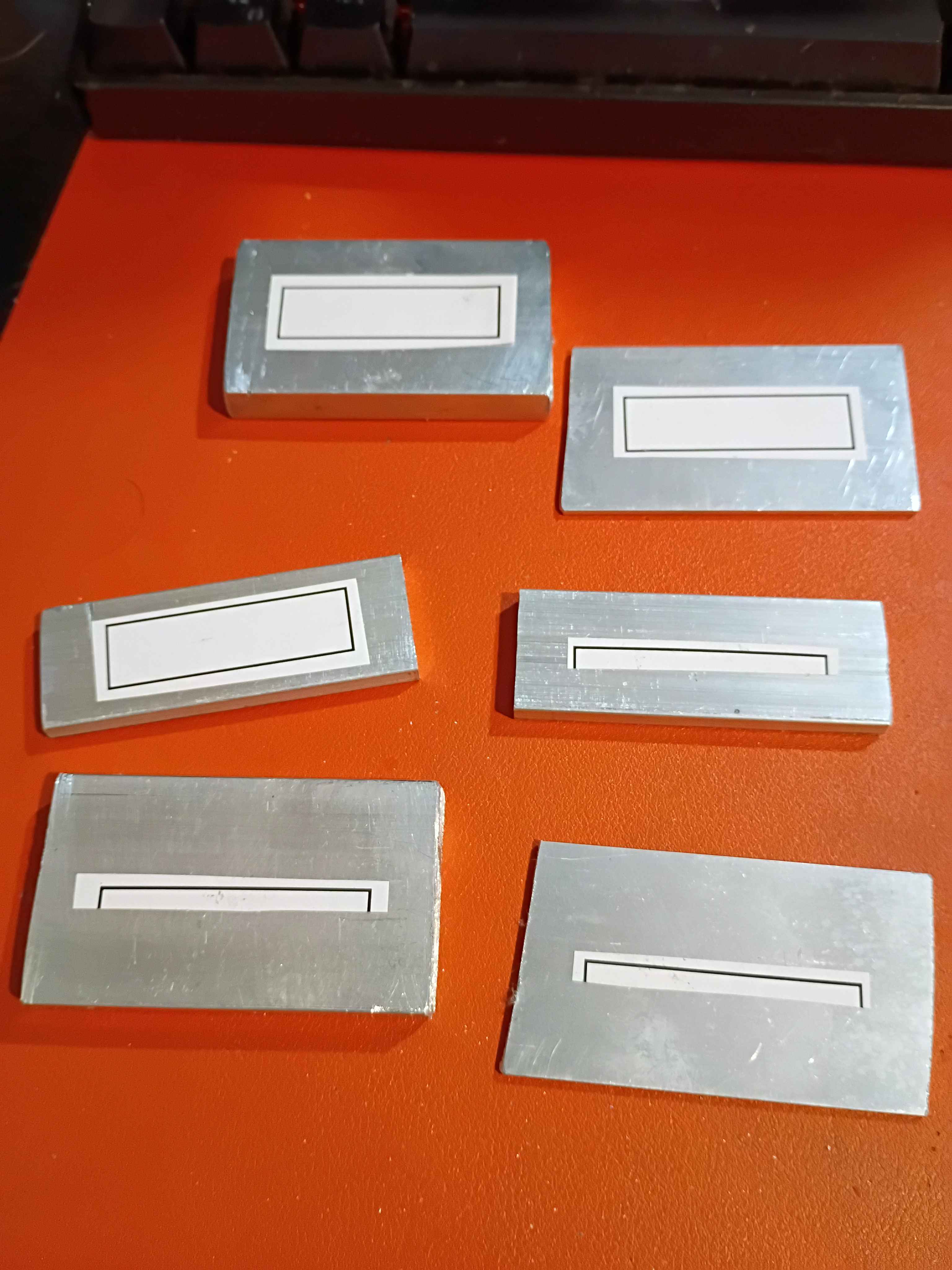
Trimmed roughly a quarter inch off the end of the ballscrew to make the entire Y-axis motion assembly fit in the frame interior (barely). Installed the stepper motor bracket in the proper location and then installed the stepper itself. Determined that 18mm of shimming will be required below the ballscrew support blocks. I have various aluminum stock thicknesses that together stack up to that value, and I can cut and drill those this week. 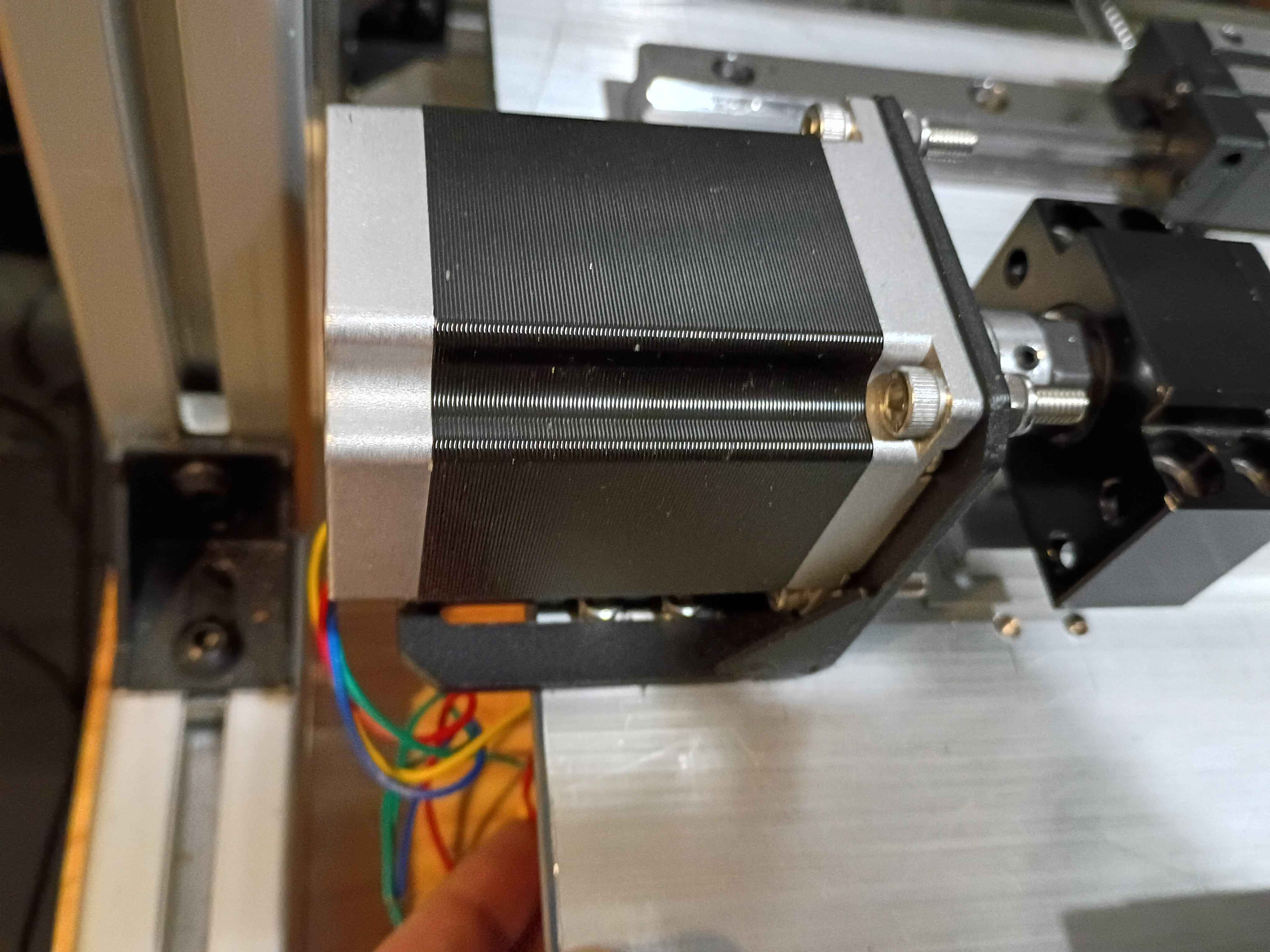
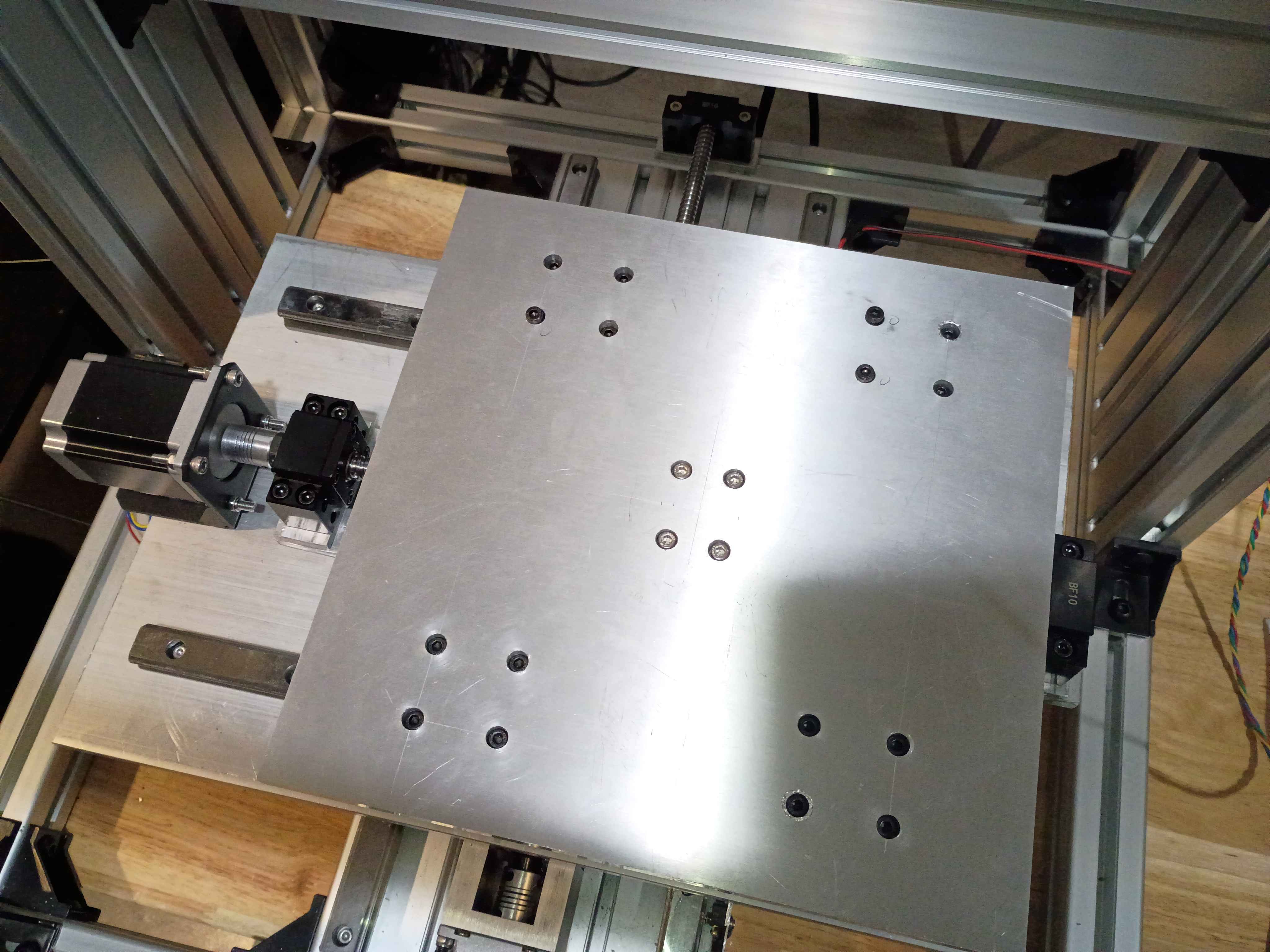
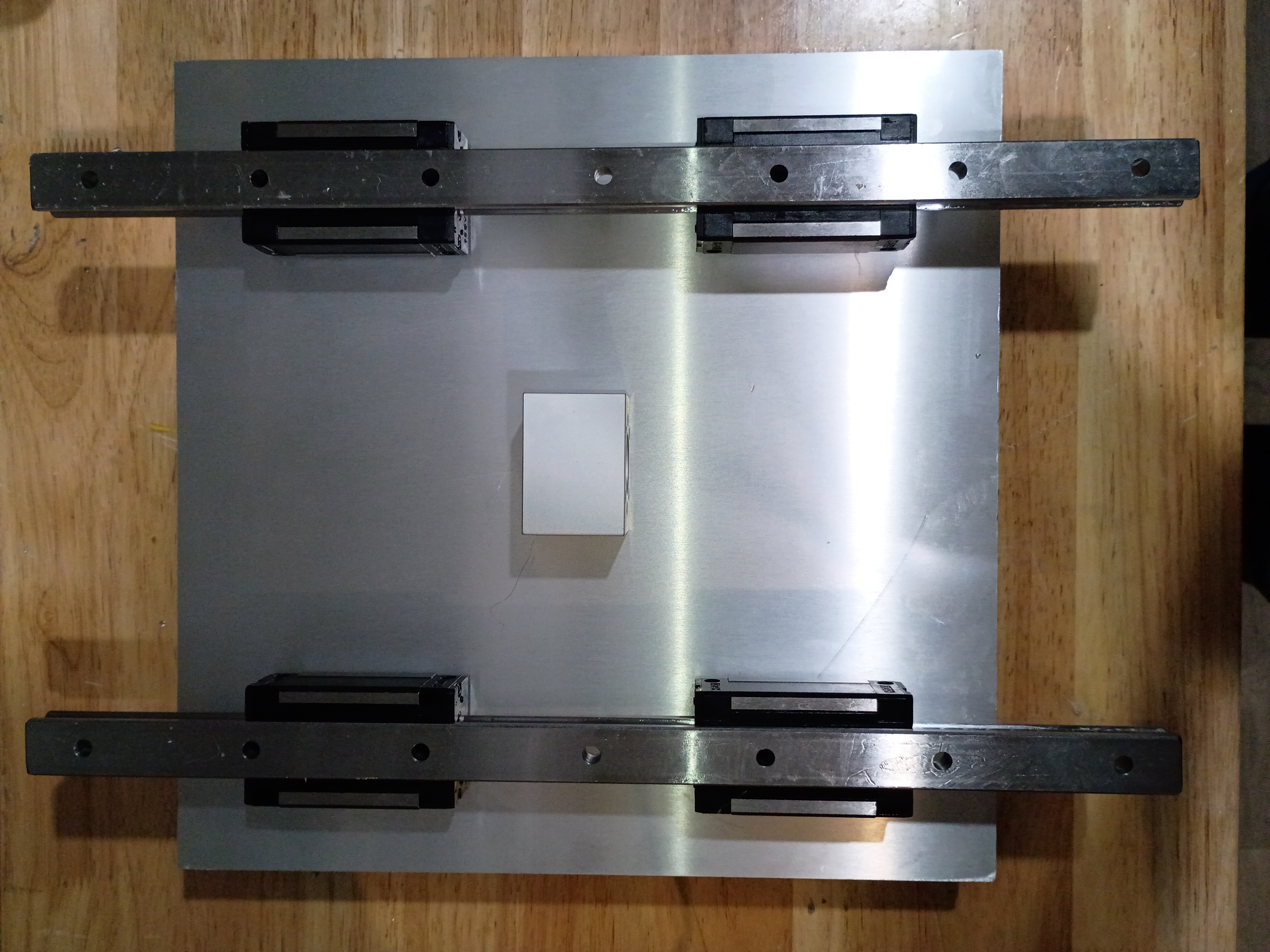
Calculated, measured, marked out, drilled and tapped holes for the Y-axis motion control on the X gantry plate. Installed the linear rails. Because space is tighter than I anticipated, I'll need to saw off a bit from the ballscrew and possibly even some from the drive shaft on the stepper. Not ideal but it should work. I'll also need a different stack of spacers between the ballscrew follower thingamajig and the XY gantry plate since the stepper mount is different, again since space is so tight. 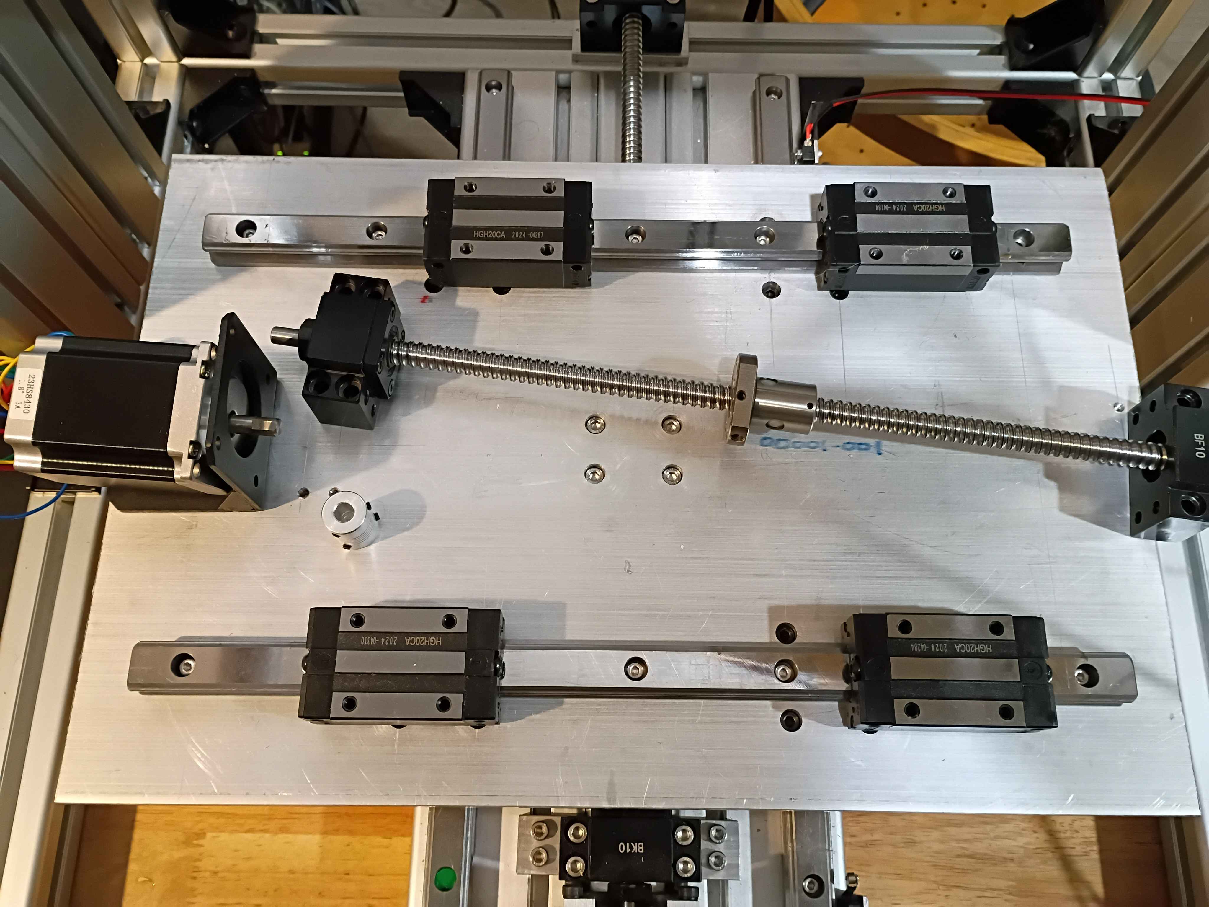
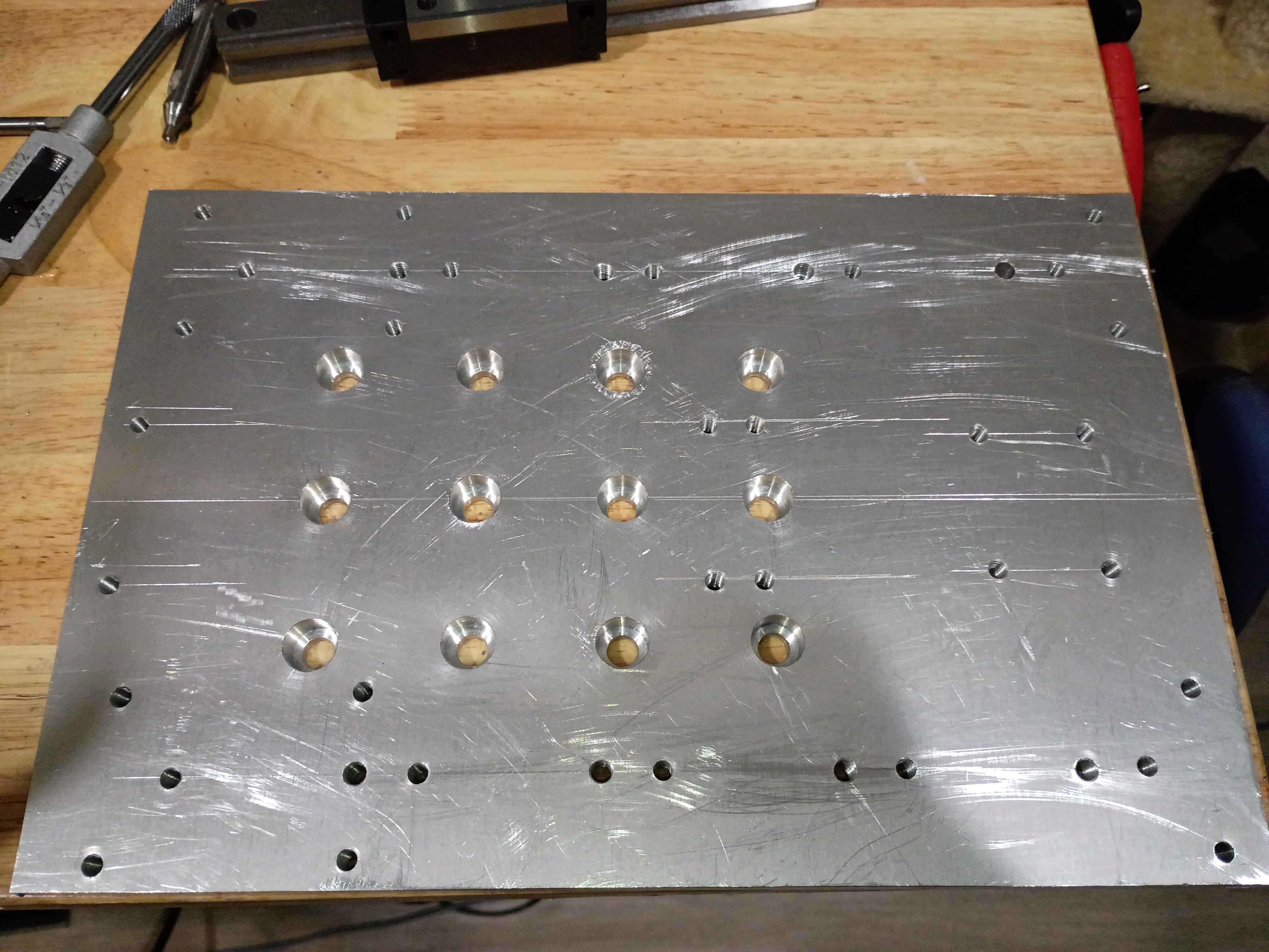
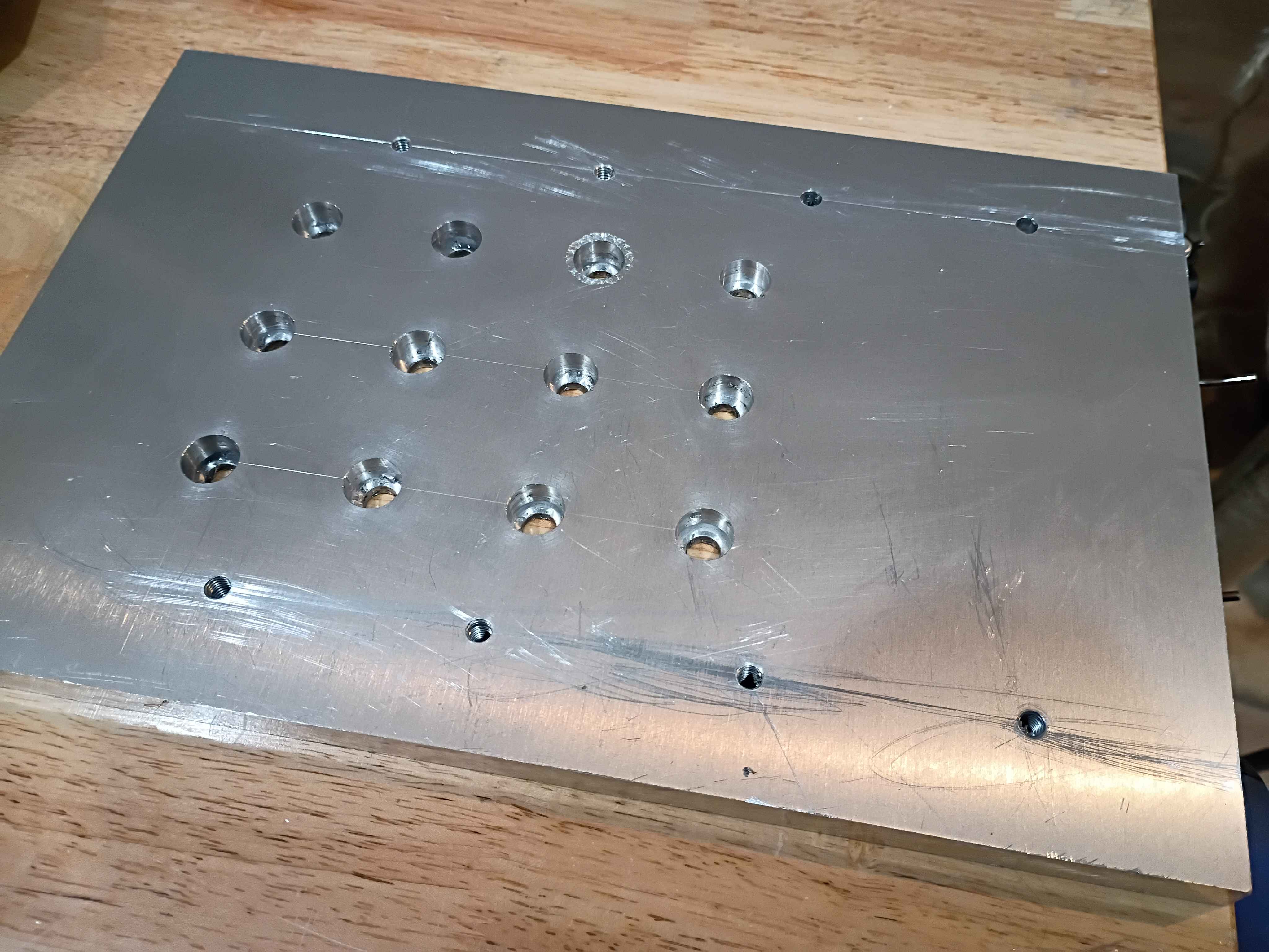
Put final counterbores into X-Y gantry plate and test-fit the linear rails and ballscrew ball nut carriage block. Somehow miraculously everything is aligned. I do still need to put in tapped M5 mounting holes for attaching things. 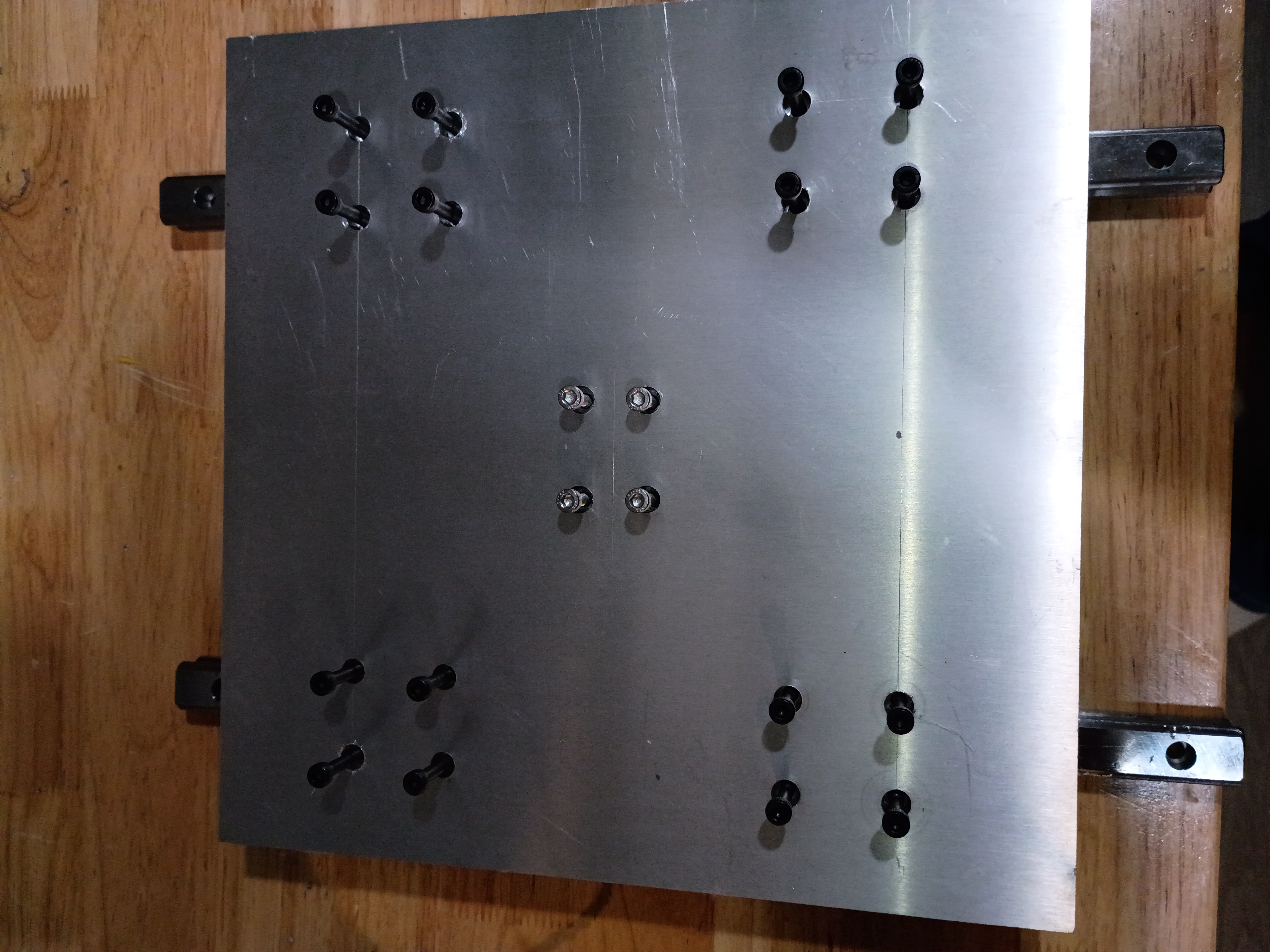
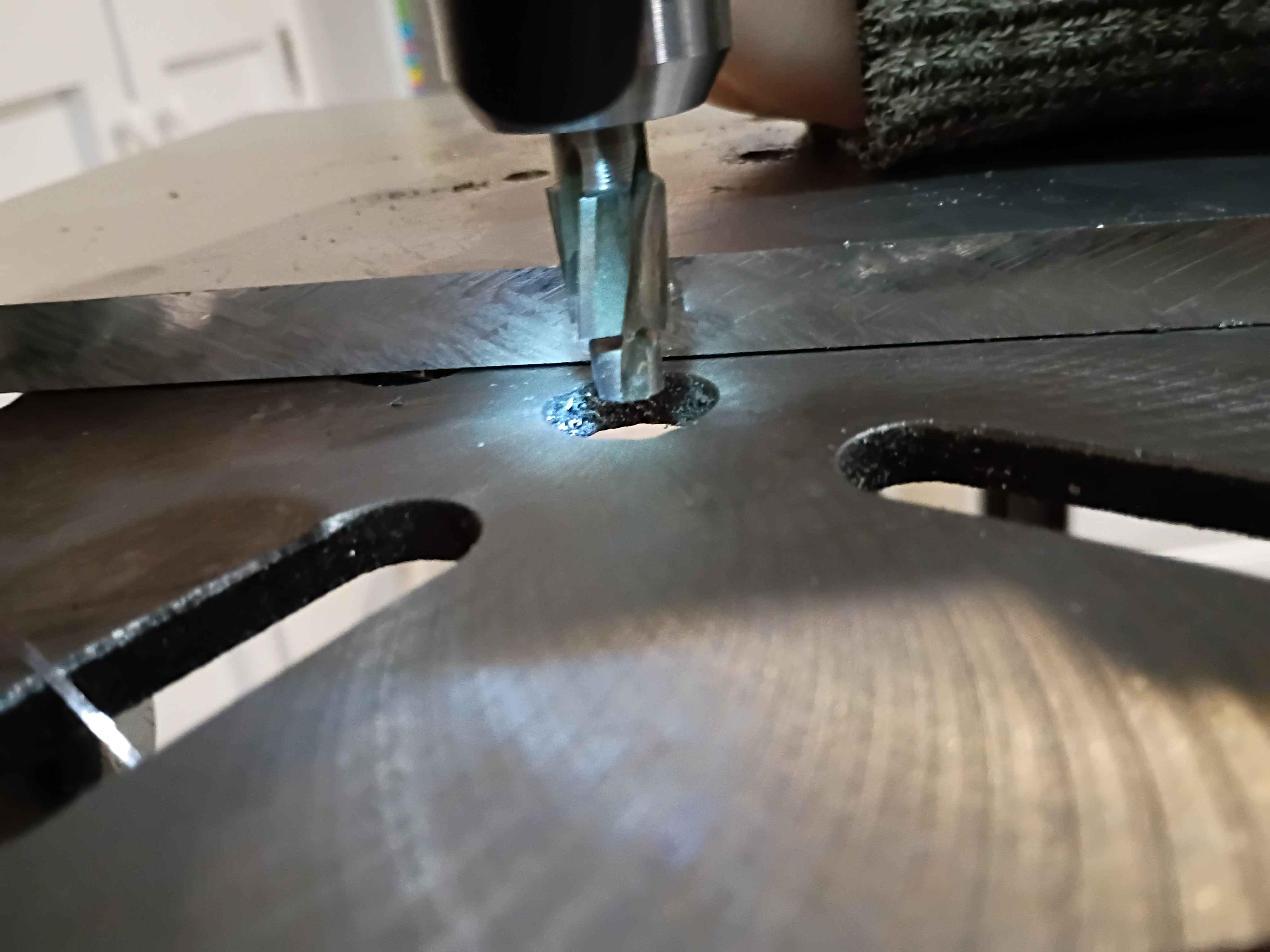
Began to drill and counterbore mounting holes for the X-Y gantry plate. These slotting counterbore bits are really nice but get gummed up quickly and stall the motor of my weak drill press. Also have to use a cordless drill to reach the central holes. Would be nice to make a nice drill press. 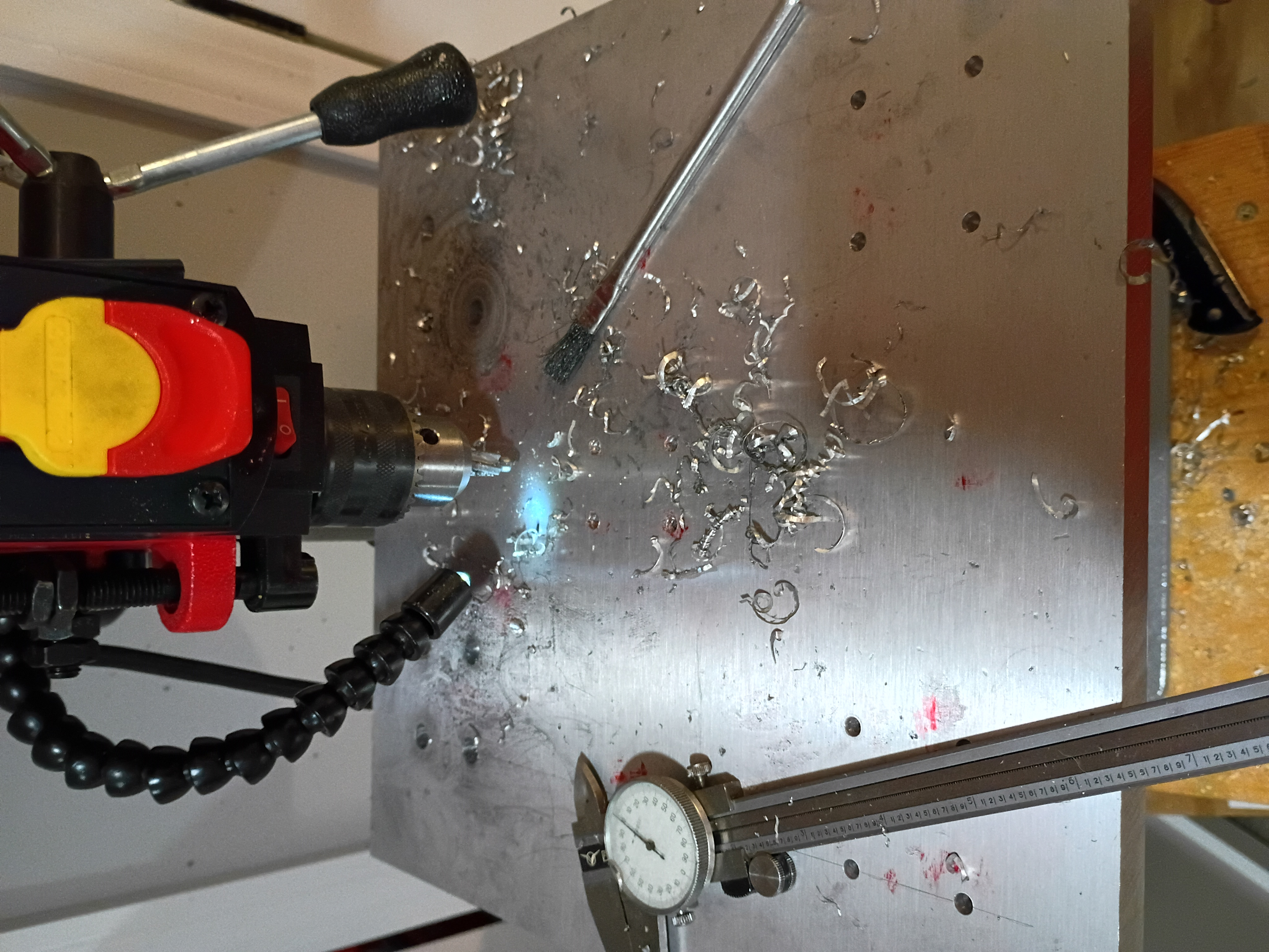
Took inventory of CNC mill project after long hiatus. Updated CAD model to reflect length of installed collet and bit and migrated to organization repository. Marked out the drill and tap locations for the X-Y gantry plate.