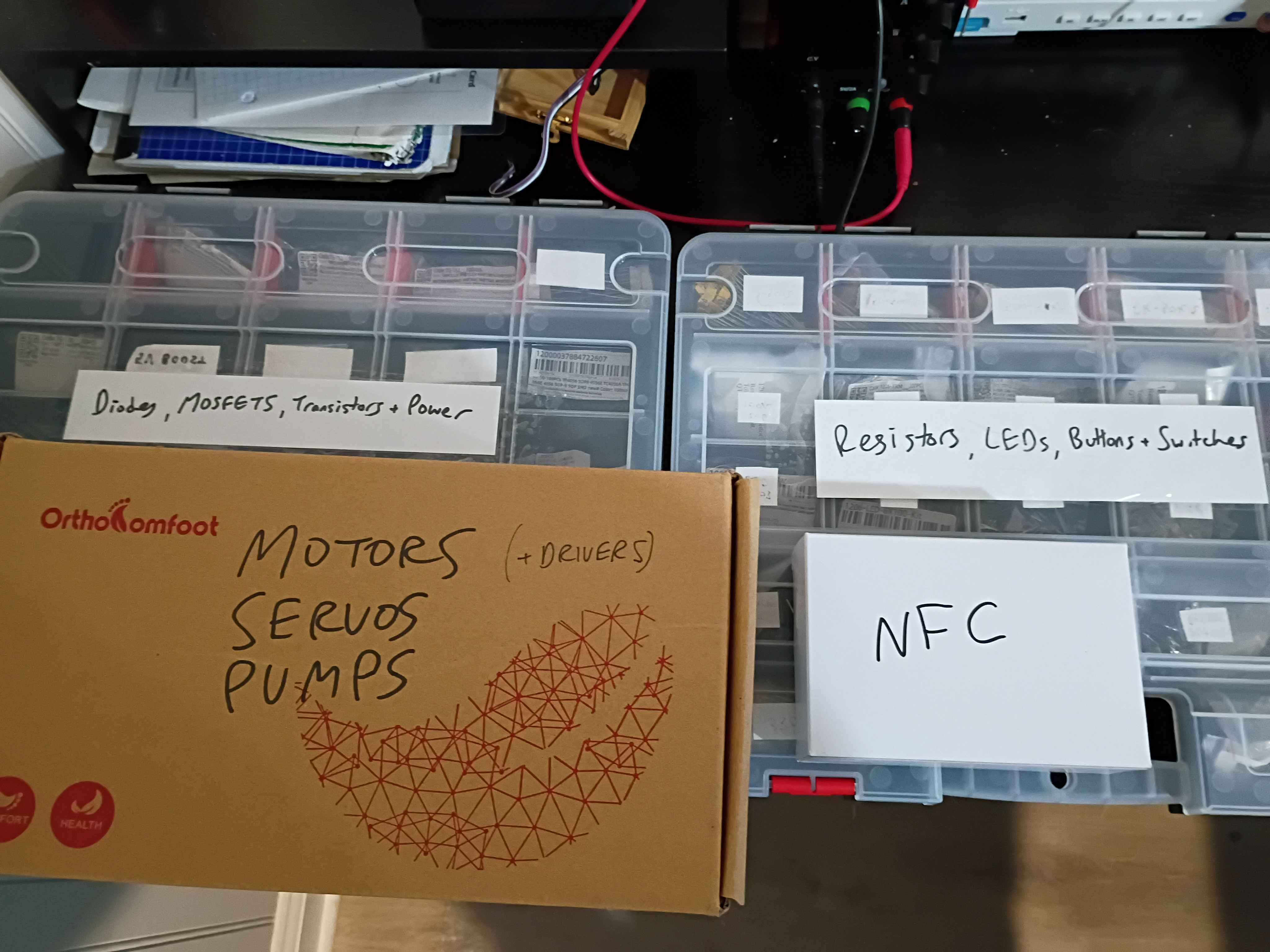
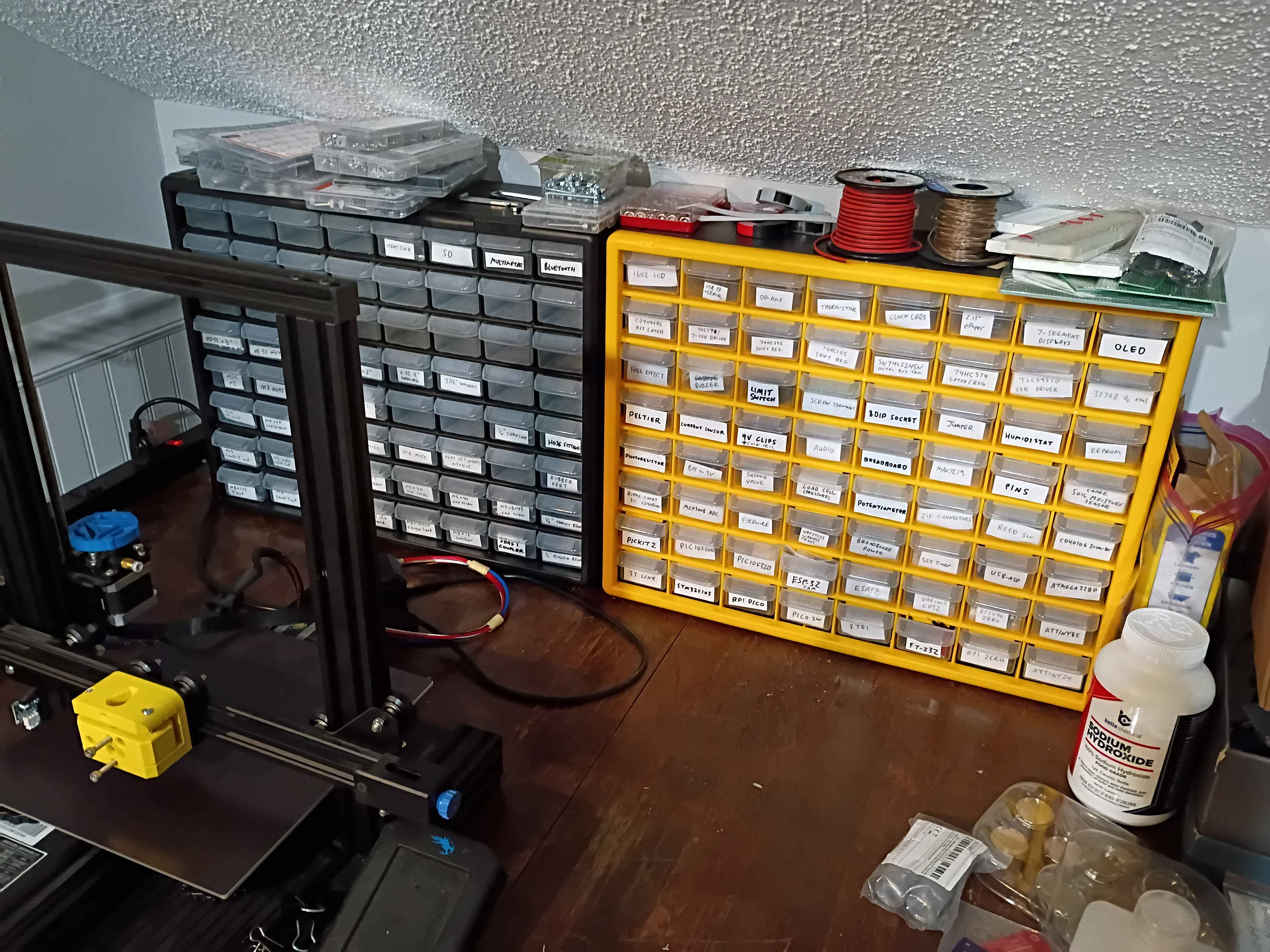
Redistributed all electronics components after recent acquisitions. Also set up a pretty good 3-camera set up for streaming and cleaned the majority of the workshop.
After a lot of floundering, determined a reasonably effective way of desoldering thru-hole components. Insert the board inverted in a vice and heat them up while pushing the exposed pin down thru the hole. A solder wick is useful to remove the bulk of the solder before attempting to push the leads thru. 
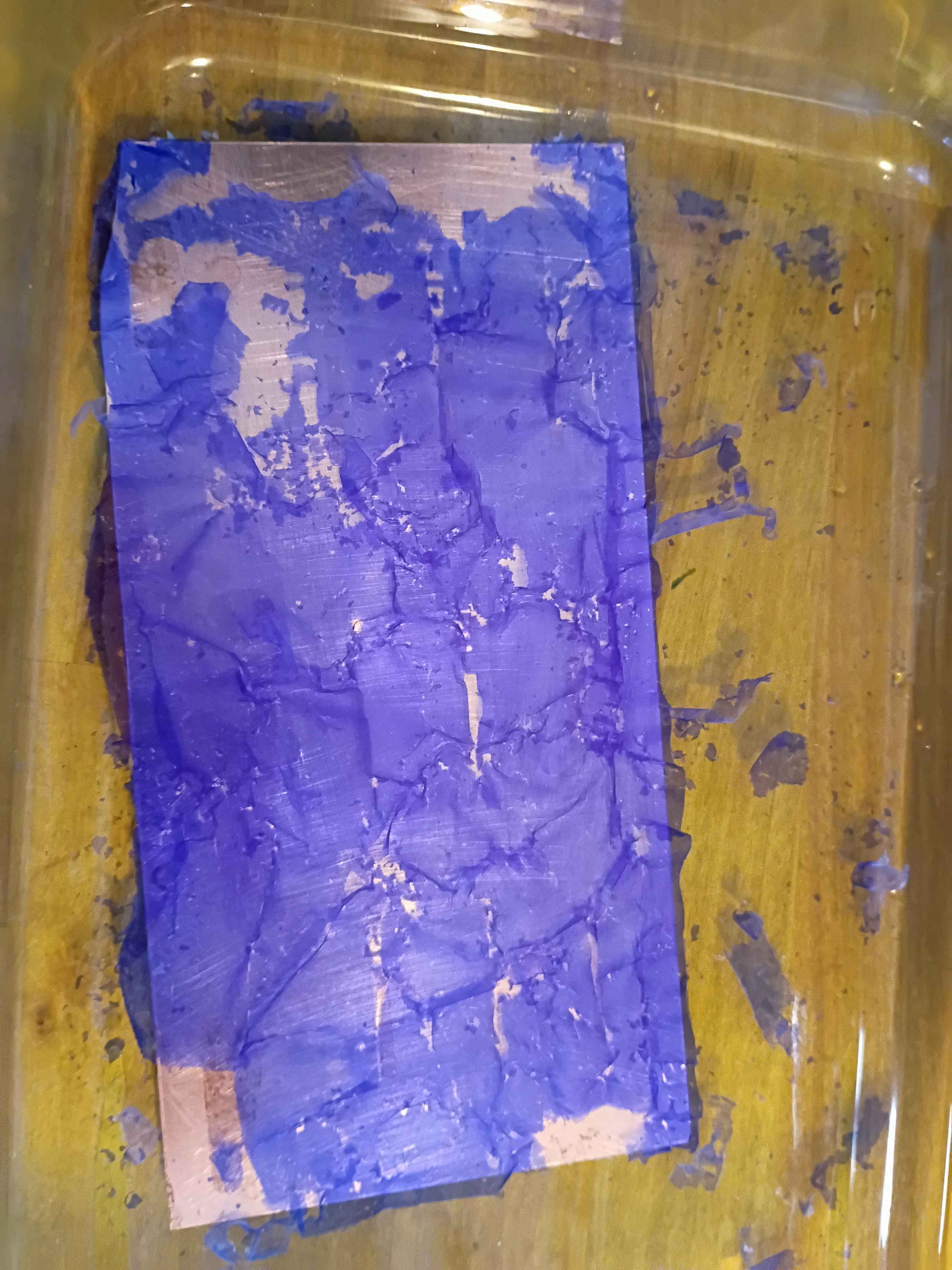
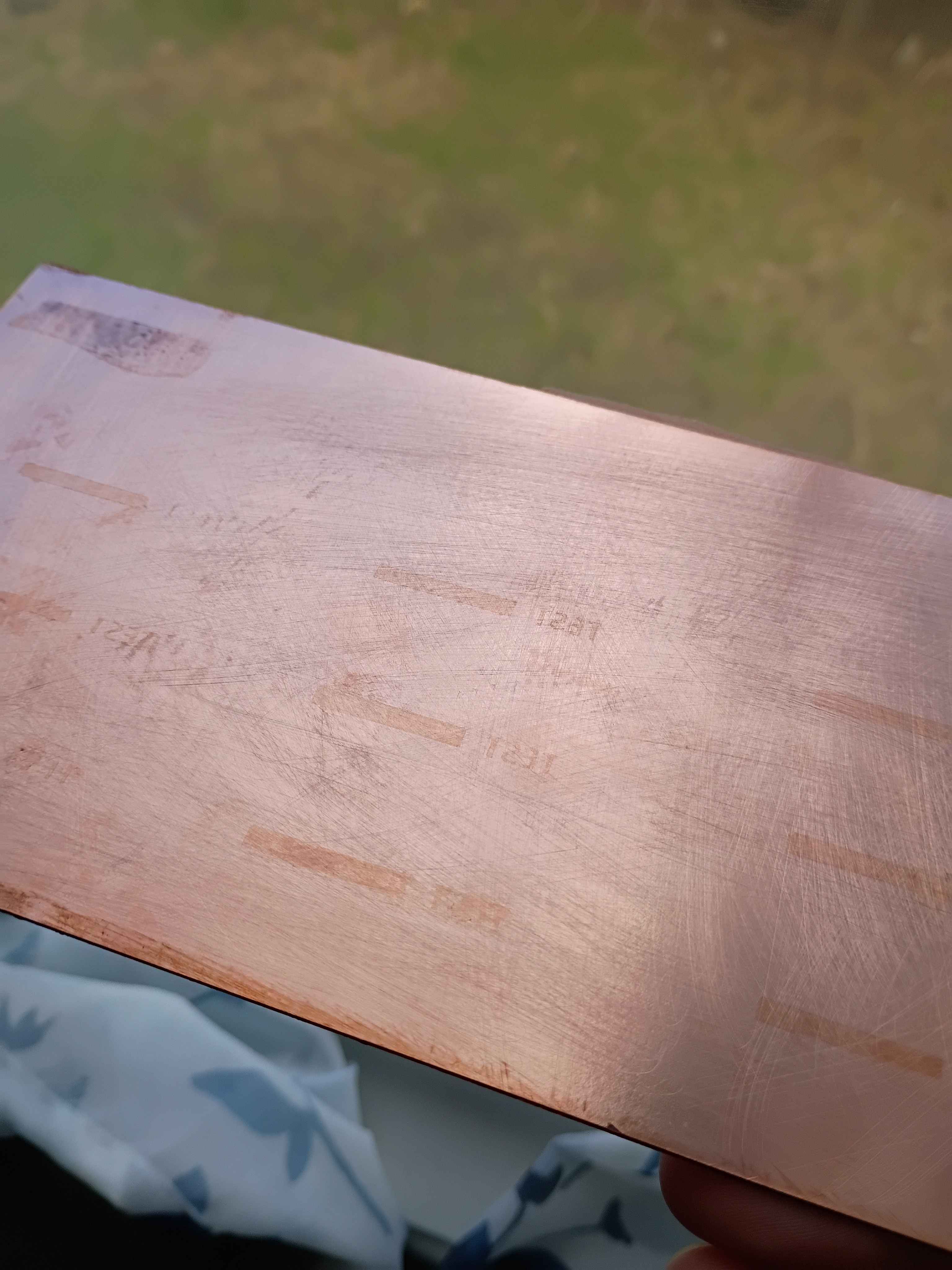
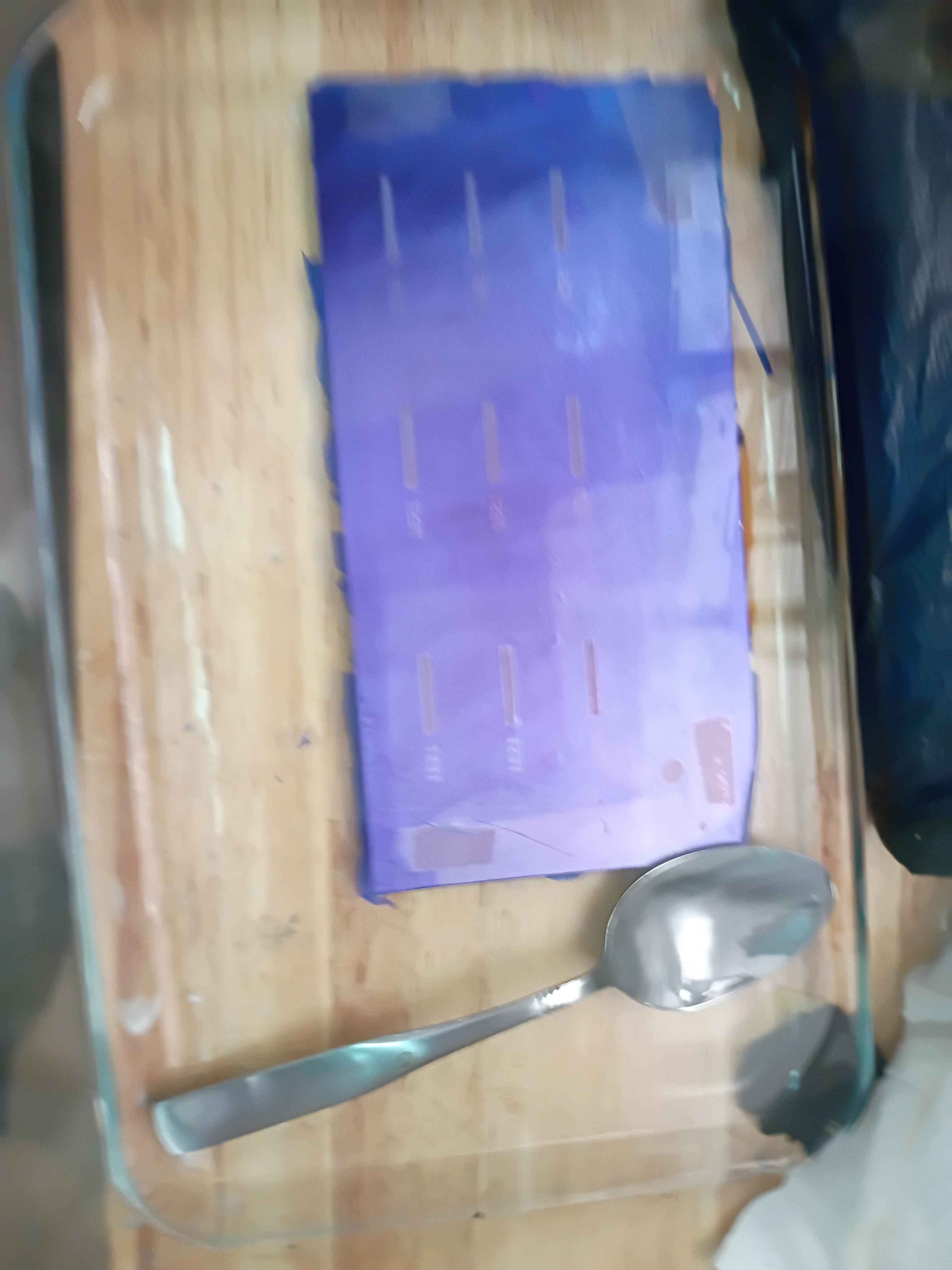
Added 2 tsp of sodium hydroxide to 500 mL of water to dissolve off the hardened photoresist on the test panel. It only took a few minutes. The only remnant was the oxidation that built on the exposed areas. 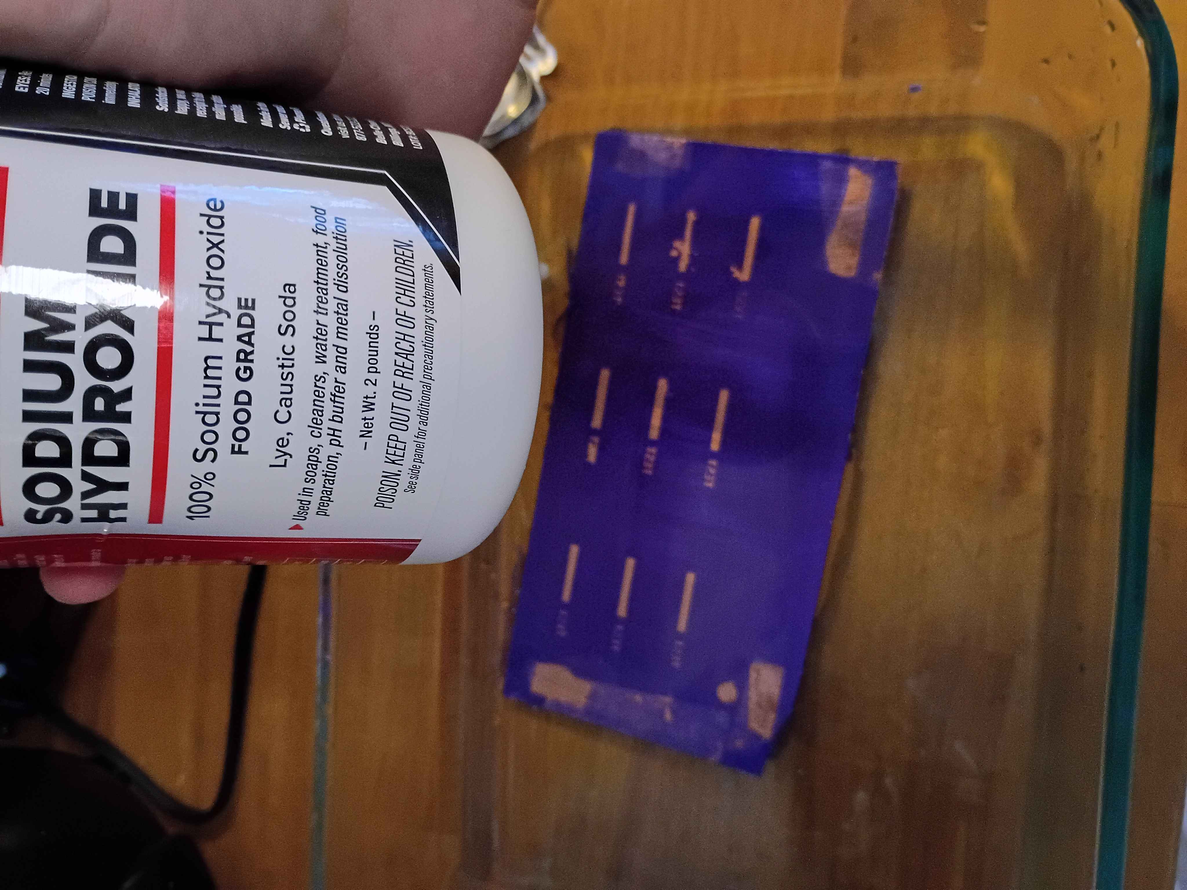
Did manage to get a toolchain working for the plotter using jscut.org. Originally I attempted to use InkScape's built-in Gcode plugin but was unable to operate on the circuit mask because there were too many paths. Eventually I figured out that you can ungroup, flatten and then reconstitute all of the features into a single path, though the order to do that requires some stumbling around. By that point, I was using jscut, an outdated browser utility, which worked decently enough. The main problem was that because I didn't have the proper hardware to assemble the plotter head, the Ultra Fine Point Sharpie was rigidly mounted to the toolhead, making it blunt rather quickly, which caused both attempts at tracing the circuit to be unusable. At some point I will retry this with a different mechanical setup because the difficult part, getting the software to work, is behind me. 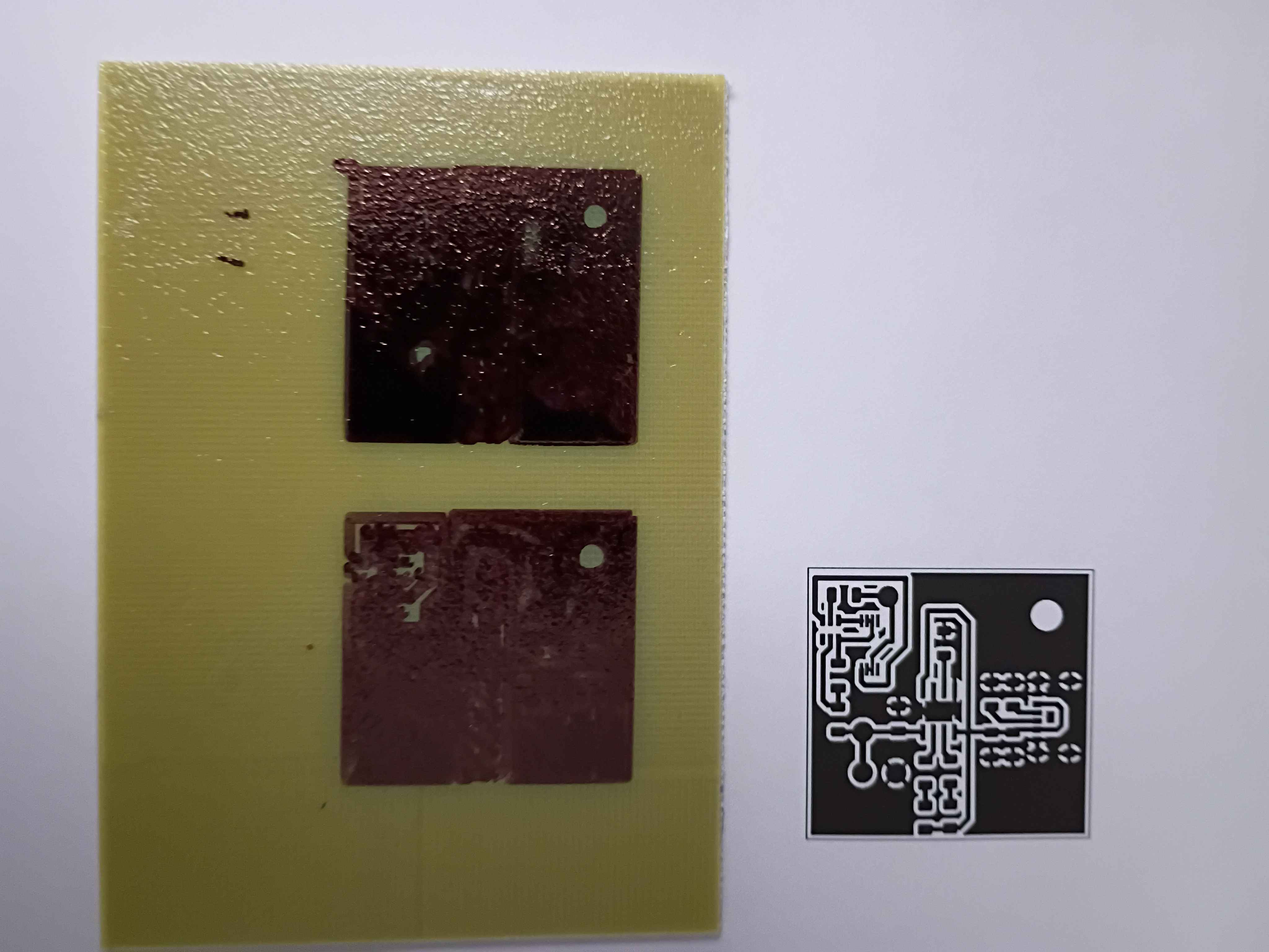
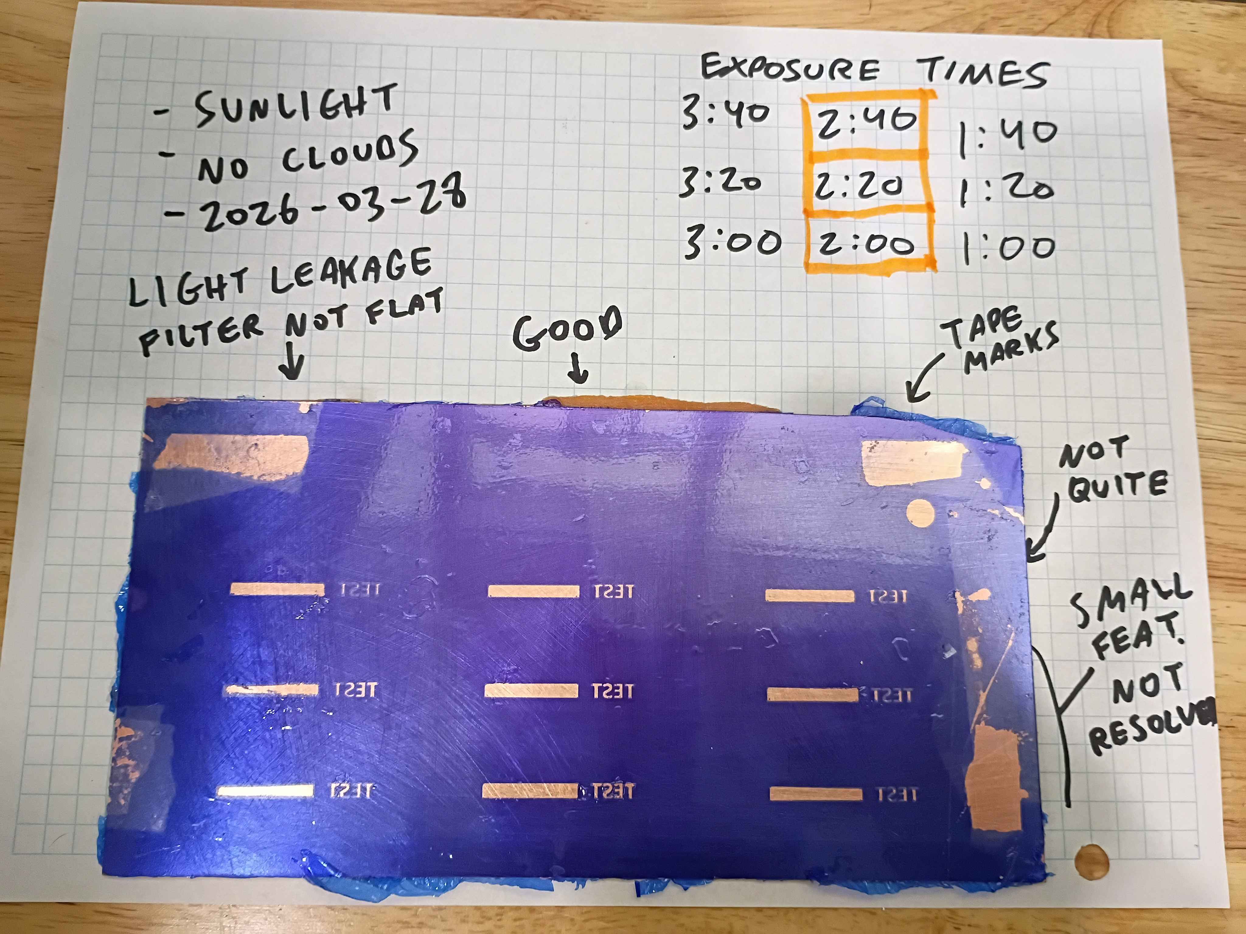
Re-attempted the use of dry film photoresist for mask transfer onto copper clad boards. Board was scuffed with 500 grit and then cleaned with acetone and IPA (actually I messed up the first film transfer and removed the failed attempt with acetone and wiped clean with IPA). The film was affixed mostly mechanically, with bubbles being removed by sliding them out by finger pressure. Limited heat was used, iron on low seemed not to help very much, though research suggests it helps the bond. A double layer of a light filter laser-printed on transparency sheets was taped to the surface and regions were exposed to the sun on this cloudless day in Bridgeport, CT (2026-03-28) for between 1:00 and 3:40 minutes. The filters were held flat to the surface by a thin acrylic sheet. After developing in 1L tap water with 1 tbsp dissolved washing soda for several minutes, the board was wiped dry. All the exposures >1 minute appear passable, though because the light filters were not pressed flat the entire time, the longer exposure times seem to have experienced some light leakage, though that could likely be avoided with a better clamping setup. Qualitatively the 2:20 exposure time looks best, with the 0.4mm features in the text being well defined. This is more than enough fidelity for most circuit traces and IC package pin spacing. Exposures below 2:00 also seem reasonable though the edges are not well resolved. I think this is because the photoresist is not sufficiently cured along the edges. The conclusion is that this method of transferring a copper mask with relatively fine features can be used successfully without even a UV cure station. It would appear able to resolve smaller features with a greater degree of success than toner transfer. If I were to use this in the future, I would recommend clamping a thick glass panel on the outer surface to keep the light filters pressed flat and cure for roughly 2:30. 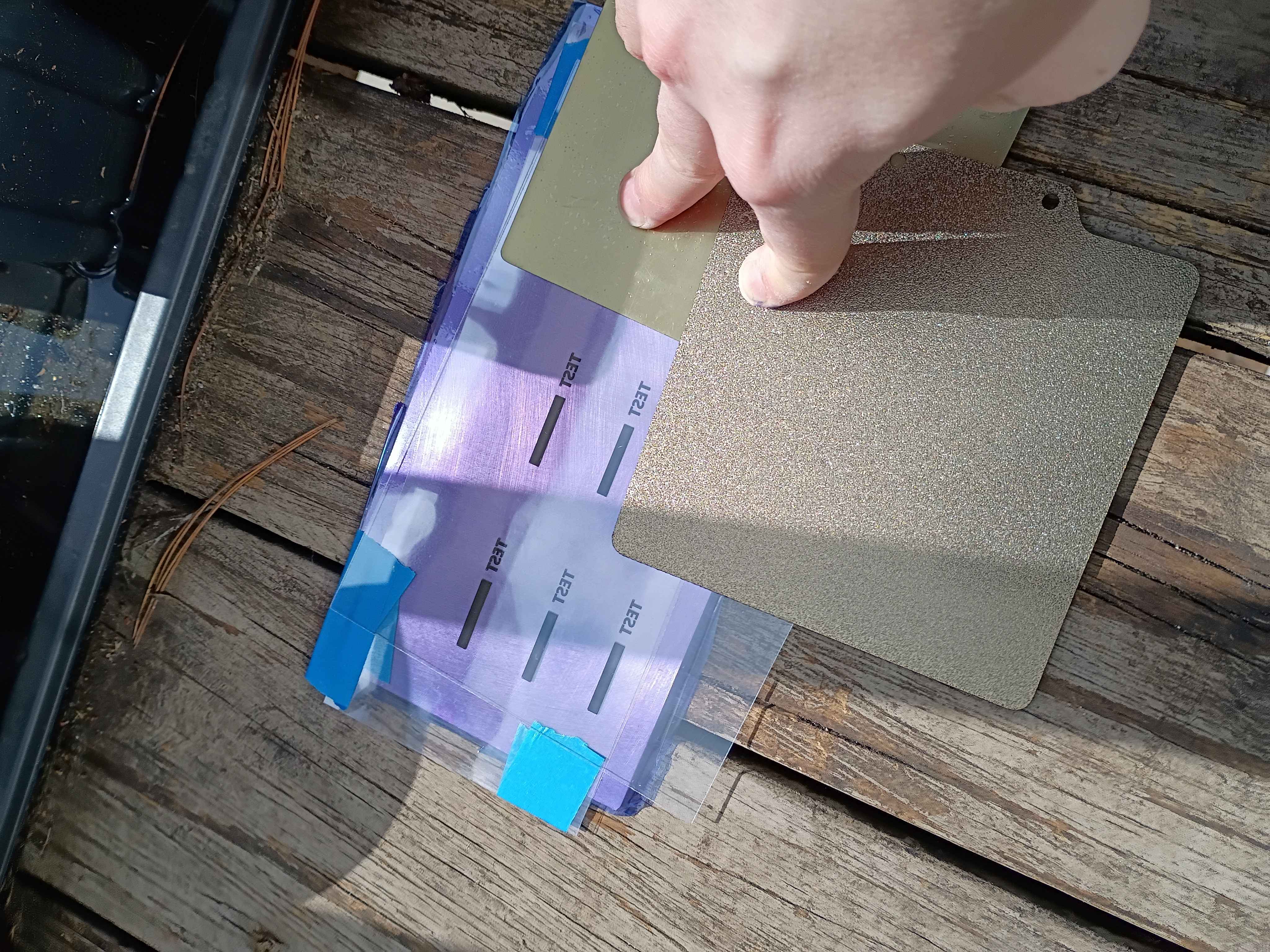
Printed and installed (with absolutely none of the correct hardware) the "pltr v2" plotter conversion to the old Ender3. Did a quick test and proved that it would work in theory to apply Sharpie as etch-resist for basic PCB production. Have to figure out how to generate the gcode for the mask with a preset X Y Z offset, but maybe I can cheat by zeroing the printer at a certain location. For reference the Sharpie lines are a bit under 1/32 inch wide, which I think will work for SOIC packages but probably not TSSOP. Still very cool. See video. 
Updated printed config files to improve print quality and seemingly avoid some common print failures I was having. Reprinted 04002-001 and 04002-002 dog bag holder with a slightly larger internal diameter as a test print. 
Designed and printed small (2cm) 3D geometric primitives for a client. Very rapid prototyping effort. 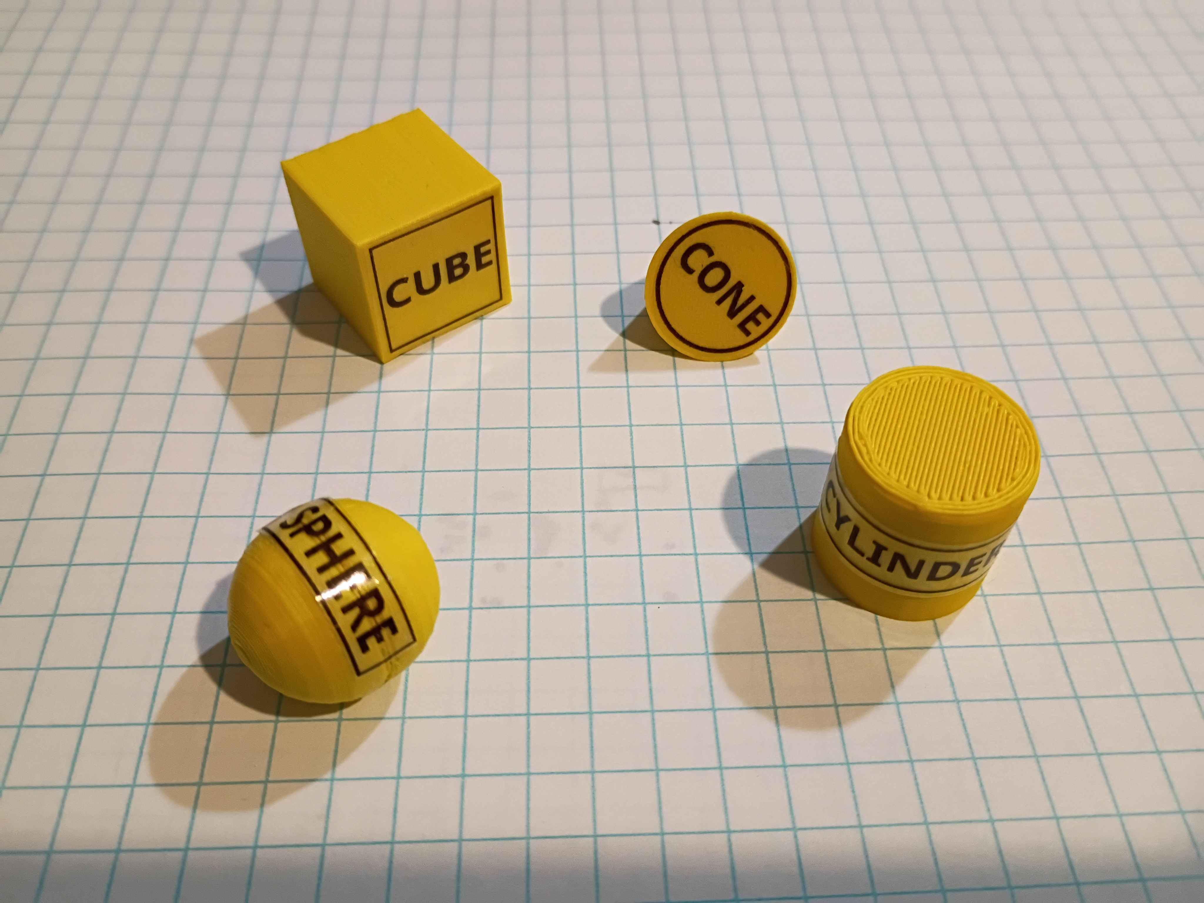
Removed silicone mat from the tool and installed edge magnets. Overall the proof-of-concept was a success, but in the future I would like to use thicker magnets set in a thicker wall and with a vent hole in the upper mold tool somewhere to prevent leakage. 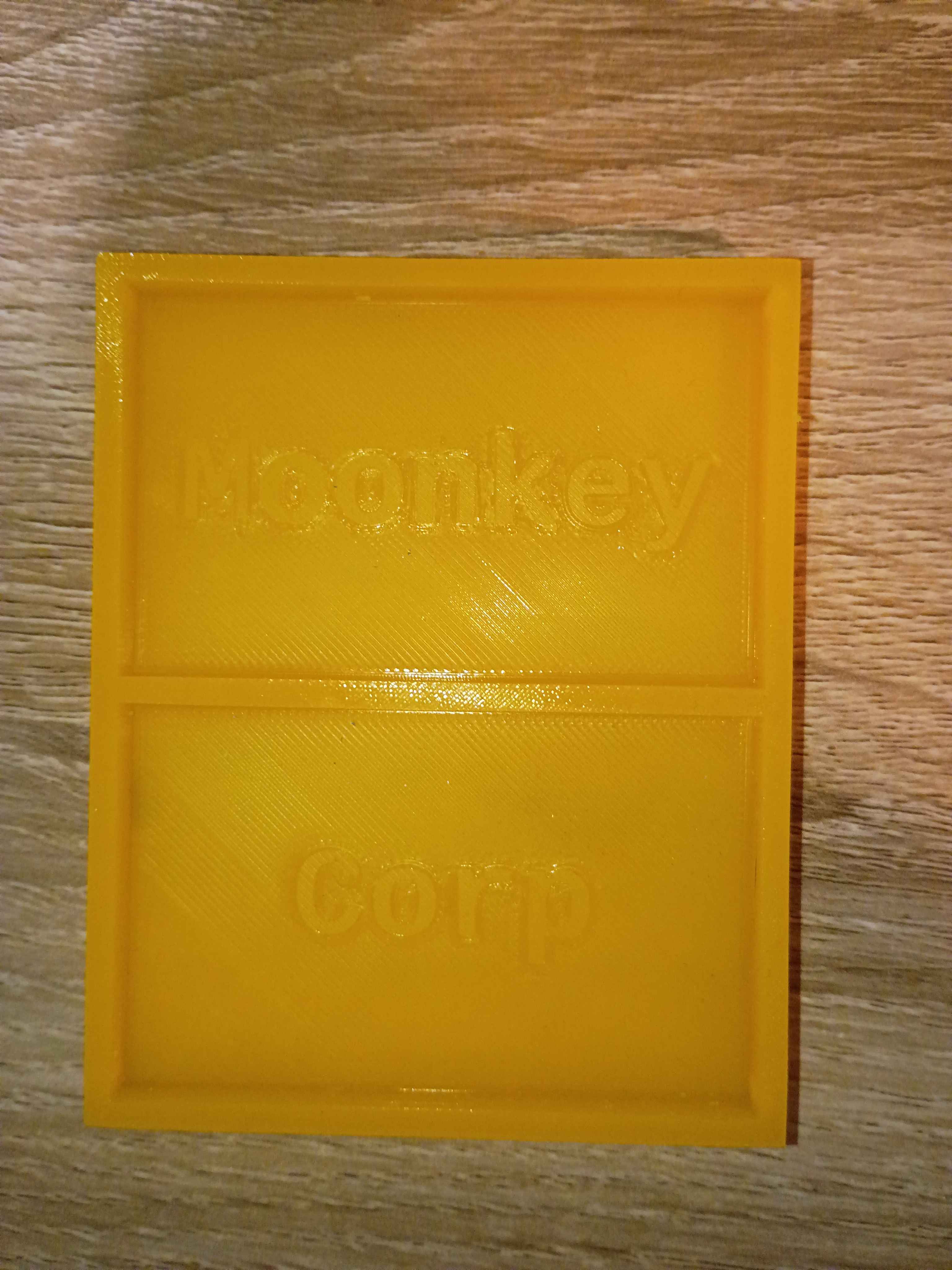
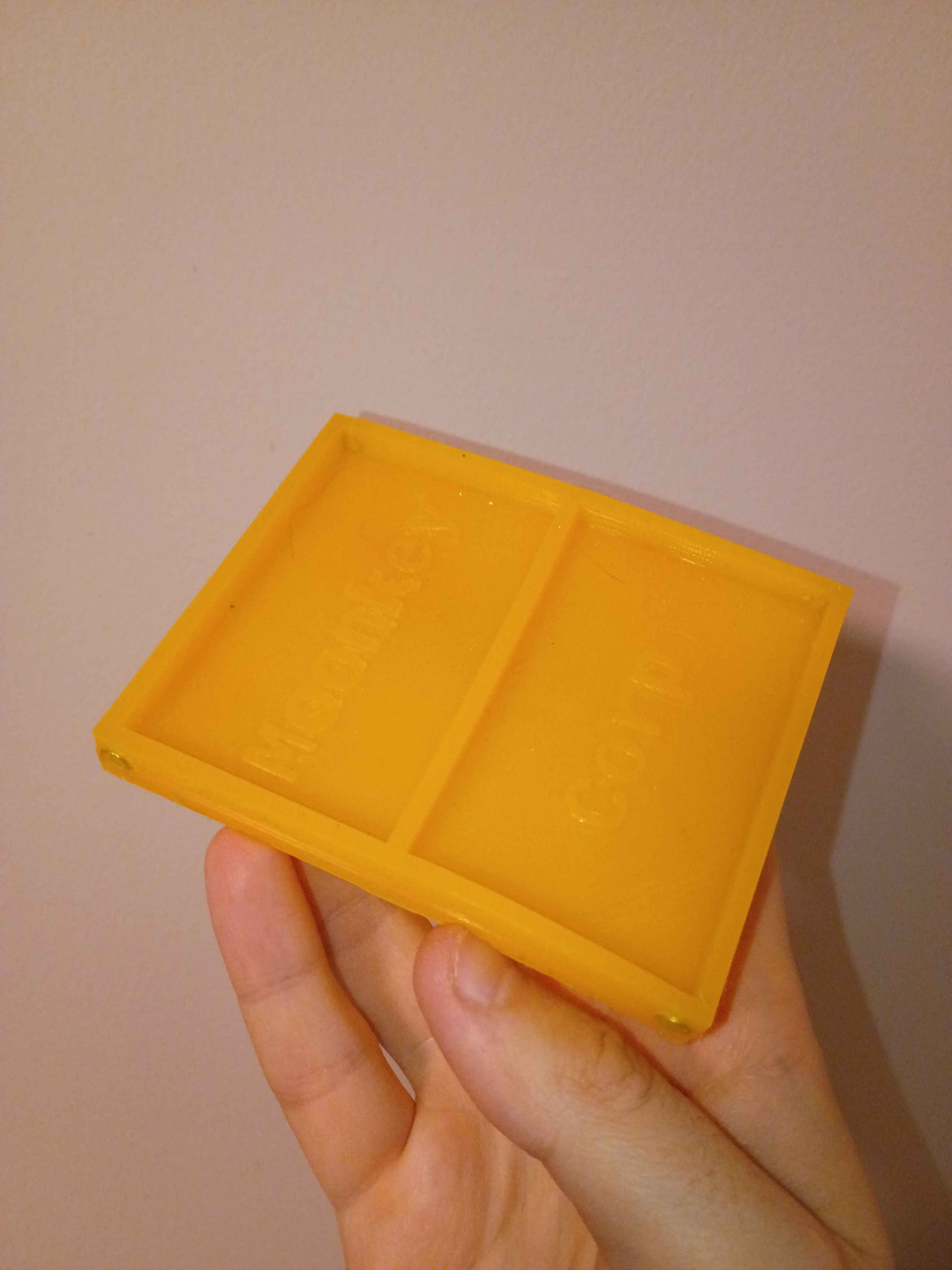
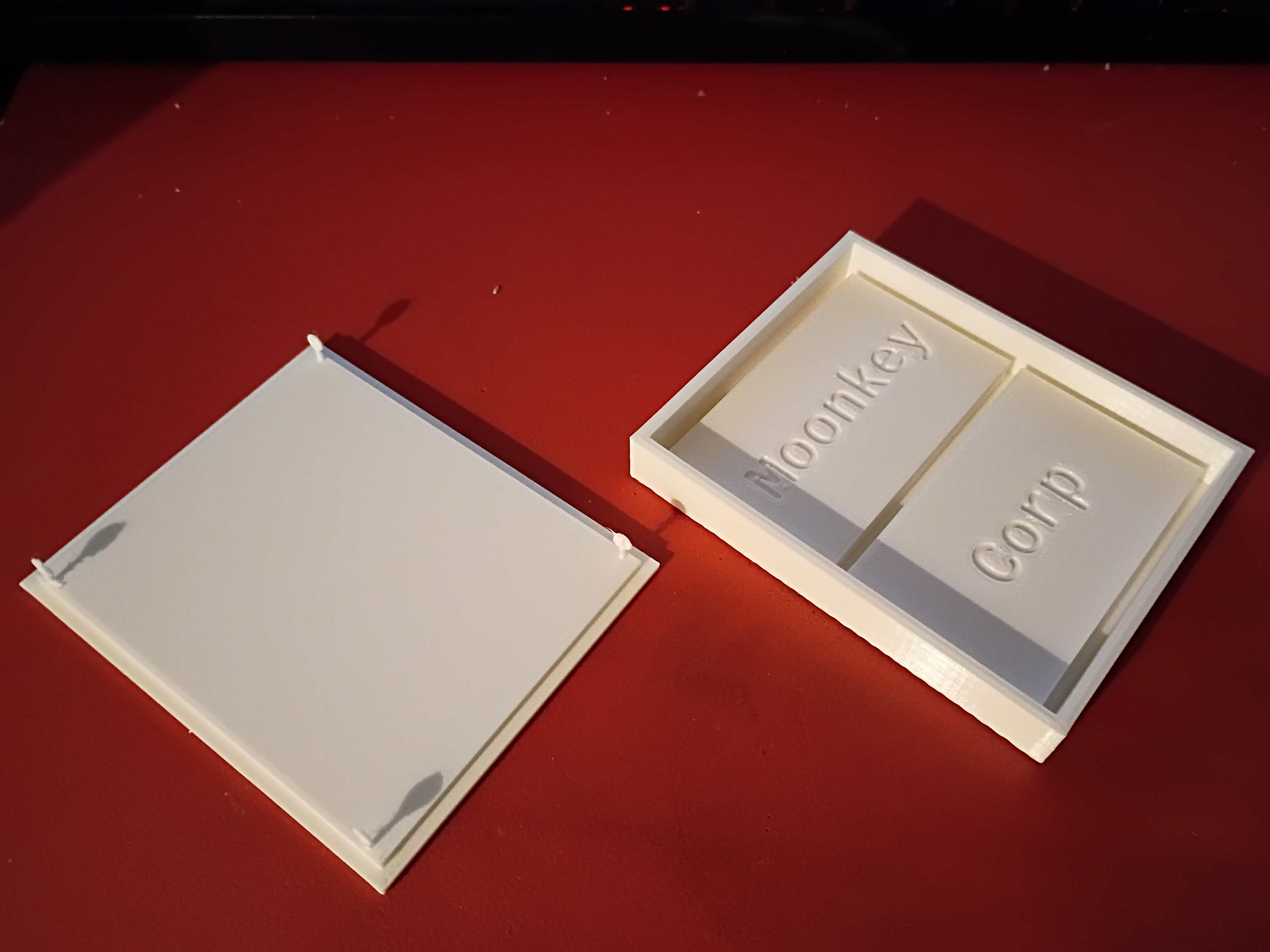
Attempted a silicone cast of the mini mat. Also had to reprint the primary clamshell mold piece due to having the text incorrectly mirrored on the first print. Due to the lack of air, I will give it 24 hours to cure and report back tomorrow. 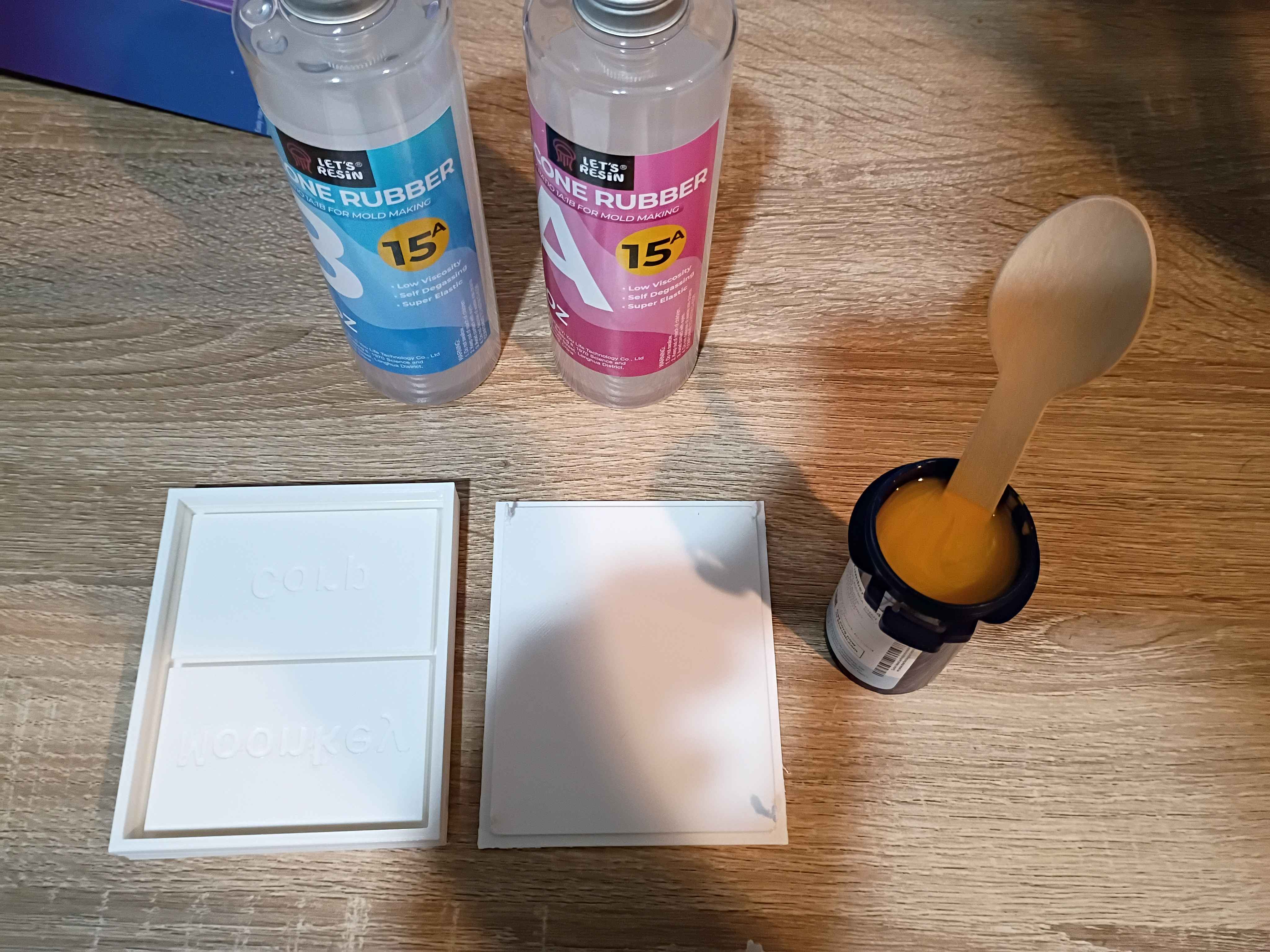
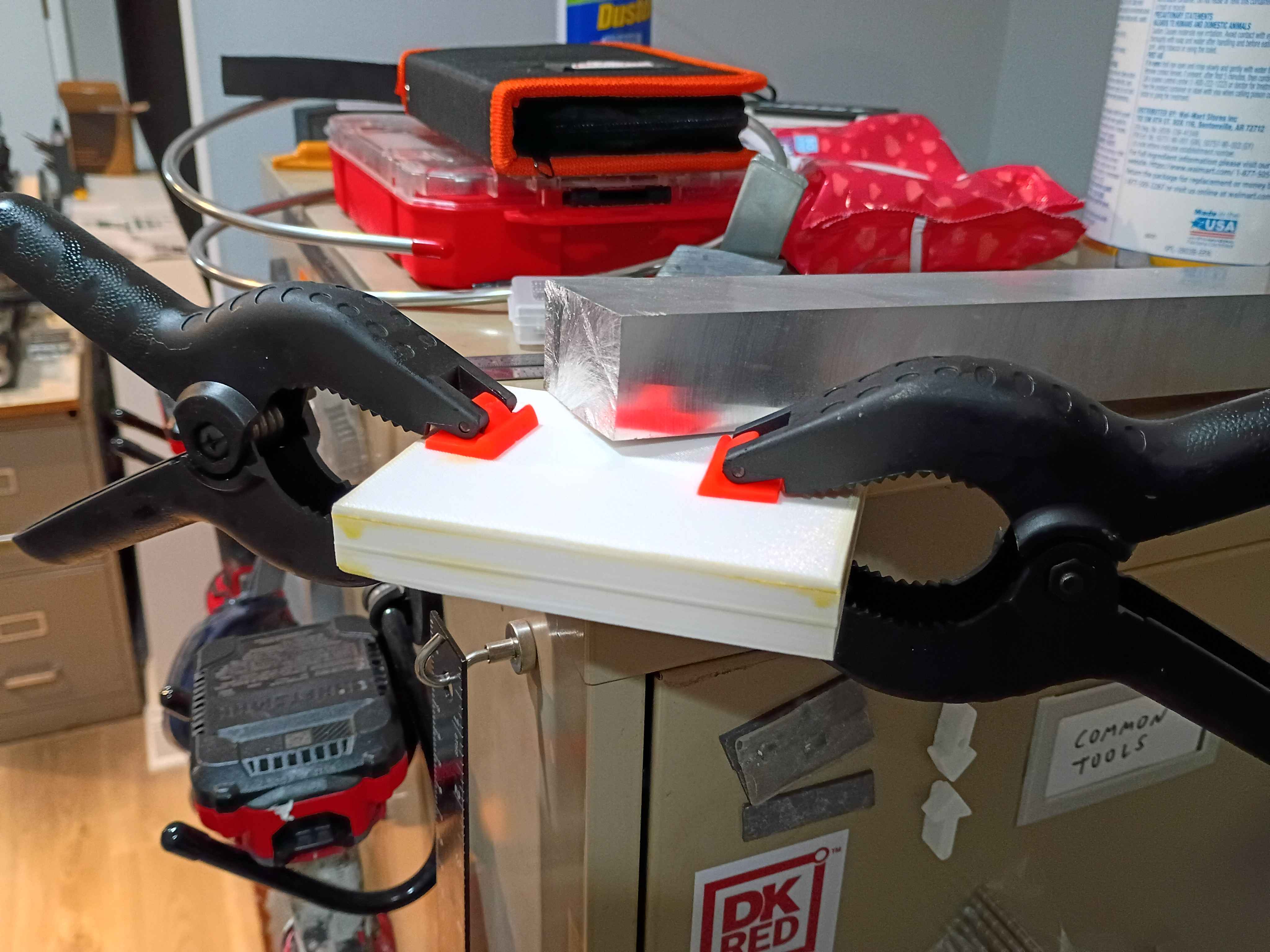
Designed and printed 2-part test mold for a silicone mat with slots for embedded magnets. This is ultimately for a potential client. 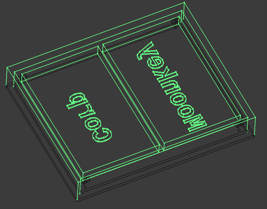
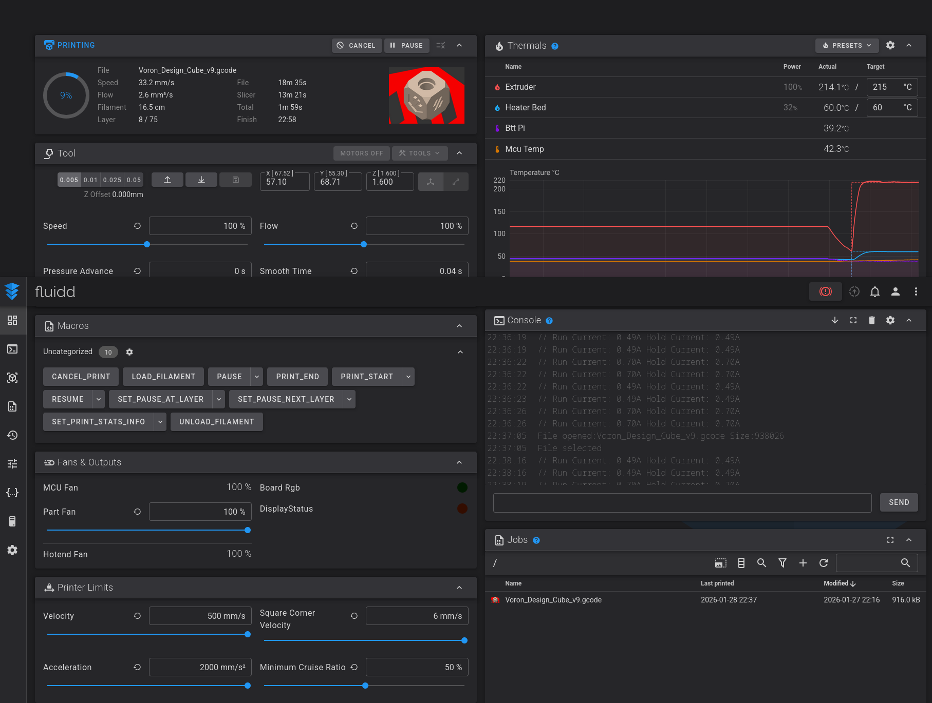
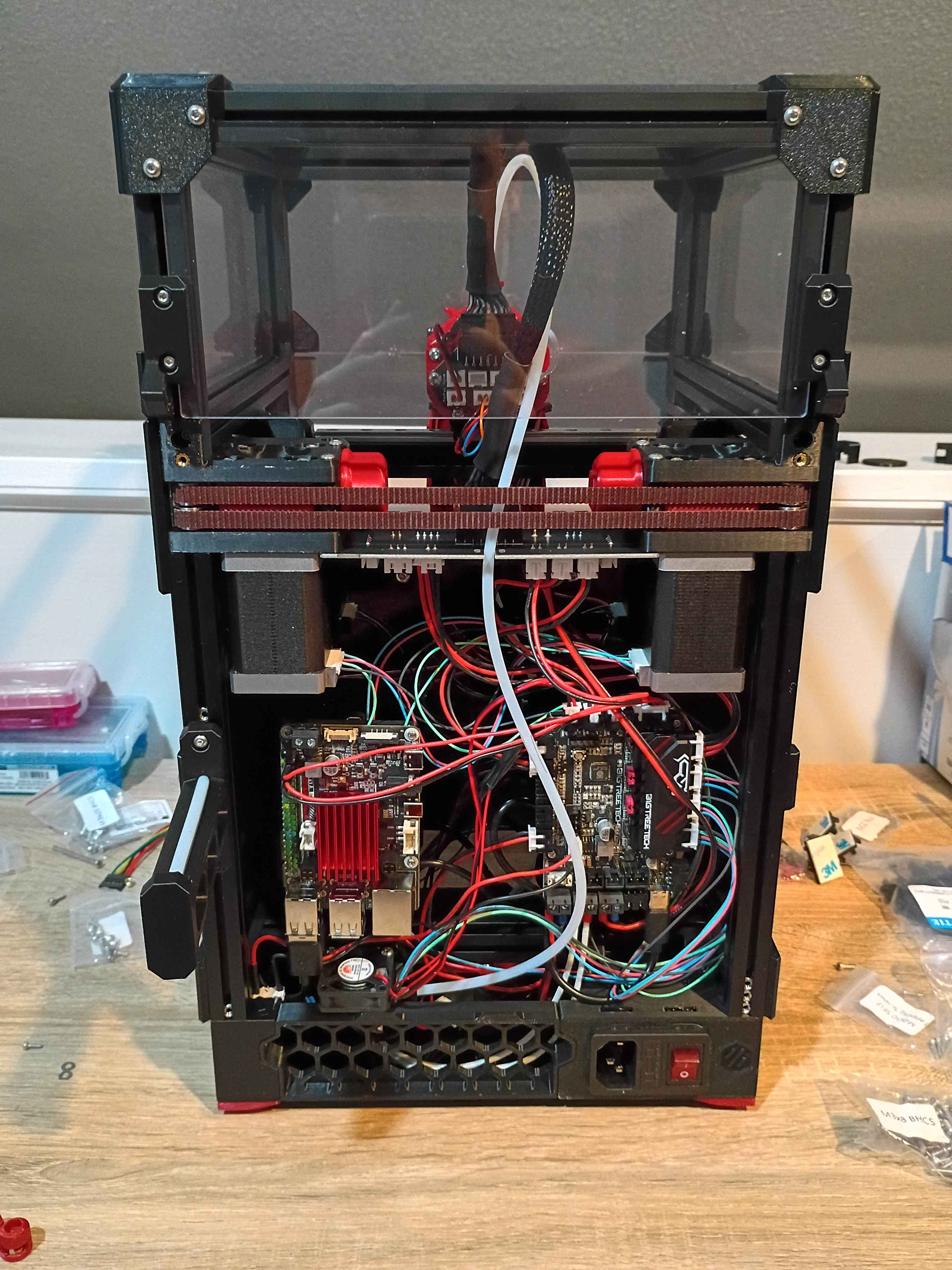
Essentially completed the Voron v0.2 build. OLED display works, wire management reasonable, back panel and top hat installed, spare parts stored away, workspace cleaned, configuration mostly set up. Several test prints completed successfully. More fine tuning will come in time, but this seems way more reliable for my purposes than my old Ender 3 V2. Props goes out to the Voron developers for this. Inspires me to make a more barebones version with a much shallower Z-depth and fewer components in general. See video of it in action. 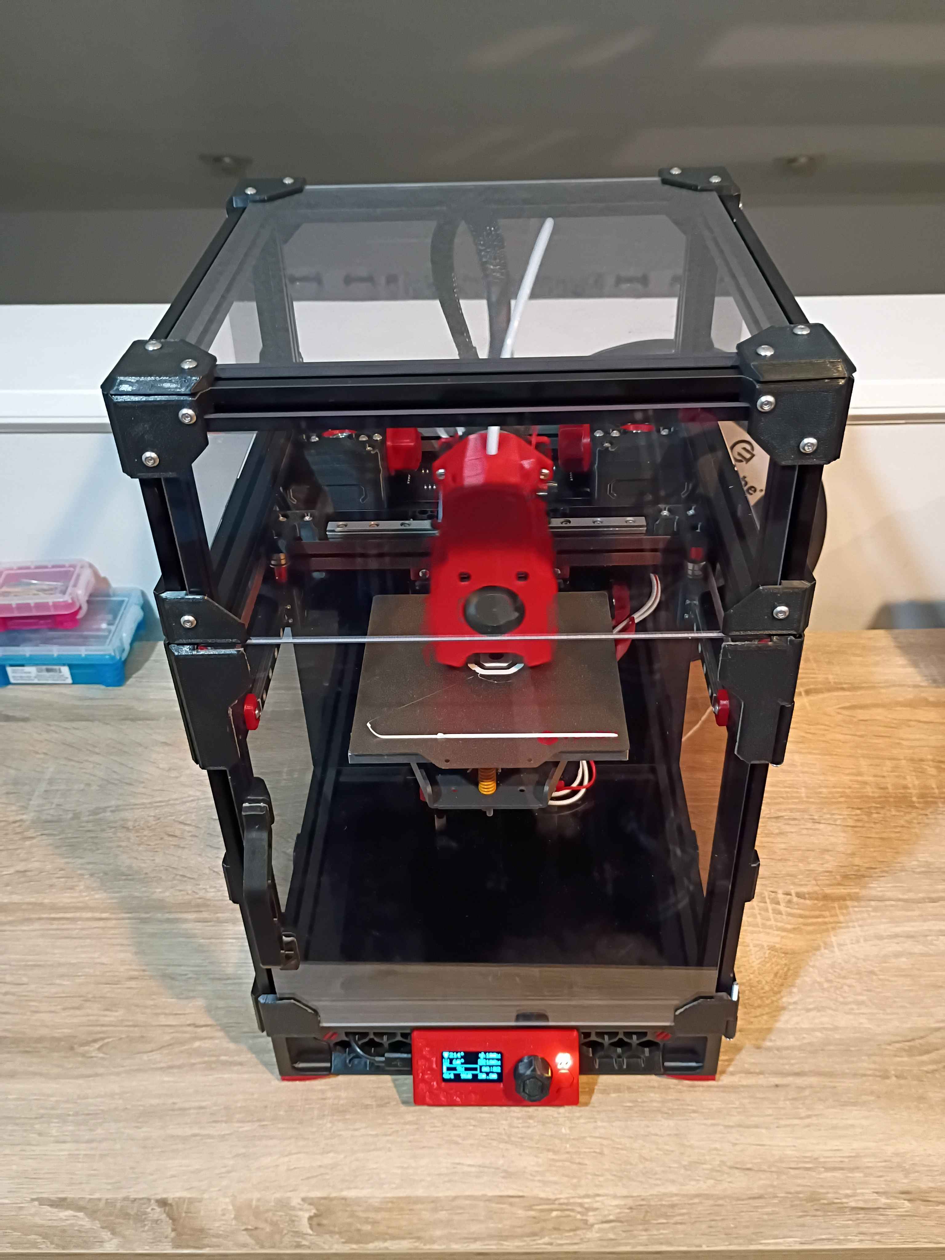
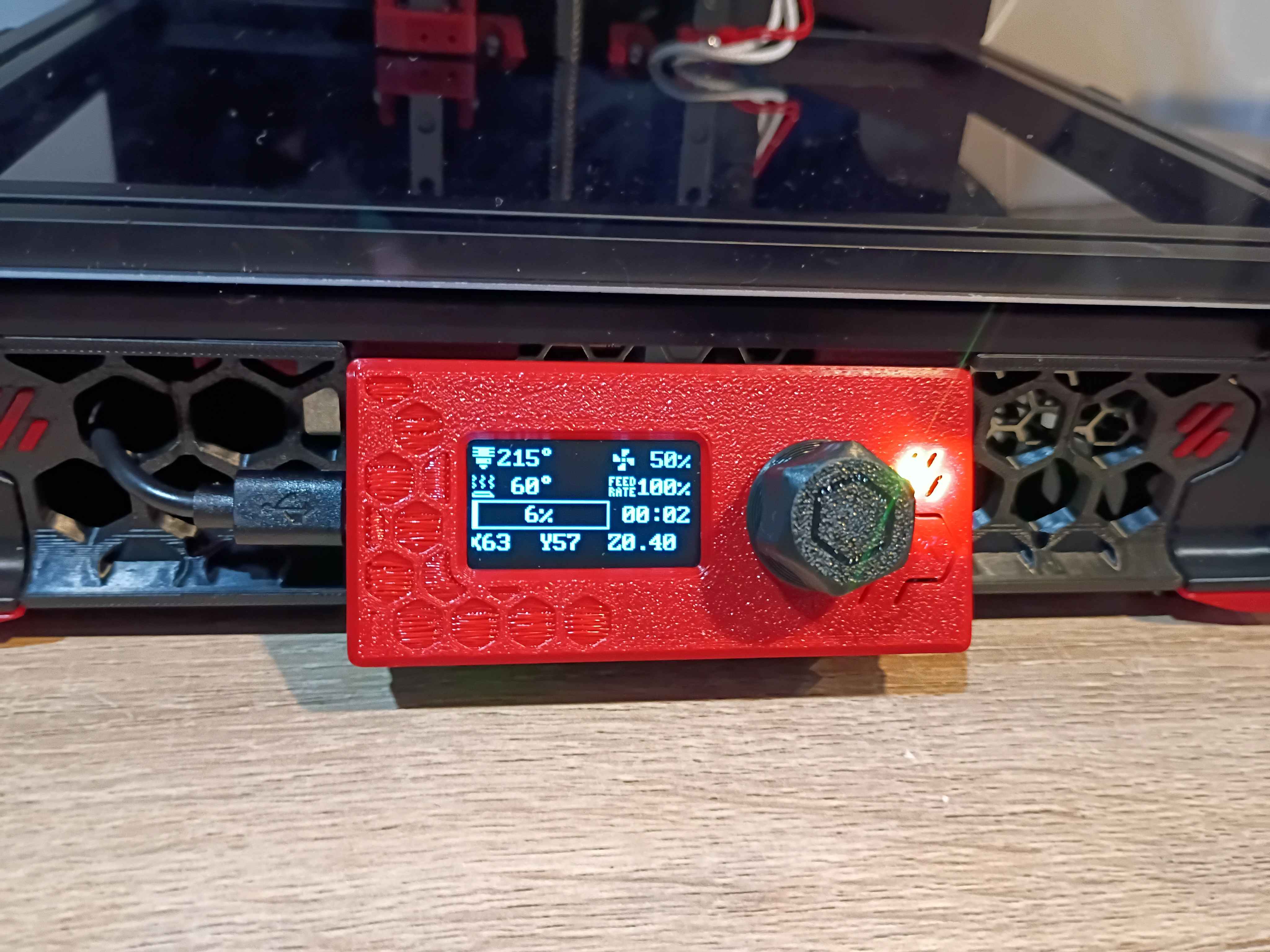
Fixed some minor electrical and software issues on the Voron v0.2 and got it printing successfully! The main issue with the electronics was that 2 sets of 2 wires were mislabeled, so I was sending negative 24V to the part cooling fans and negative 24V to the extruder fan. Found the issue, swapped them around, and it was fixed. Spent some time tuning config parameters and leveling the bed. Now that it works, tomorrow I can enclose the electronics and wrap up the build. Also the OLED display needs to be properly connected and configured - right now it only shows some default sample text. I think I'll also clean up the wiring slightly and eventually get some kind of air filter system to print ABS, though that can wait. 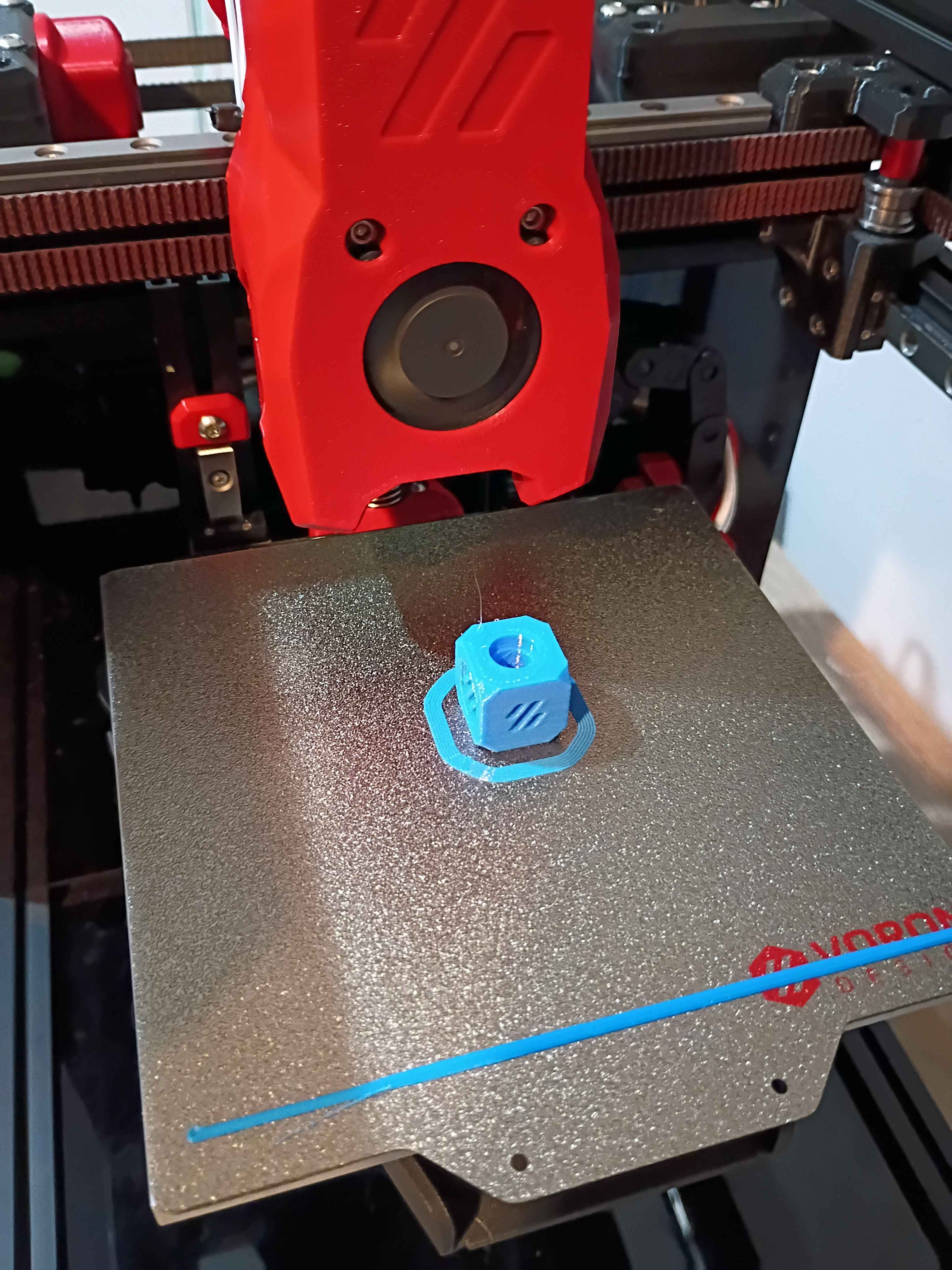
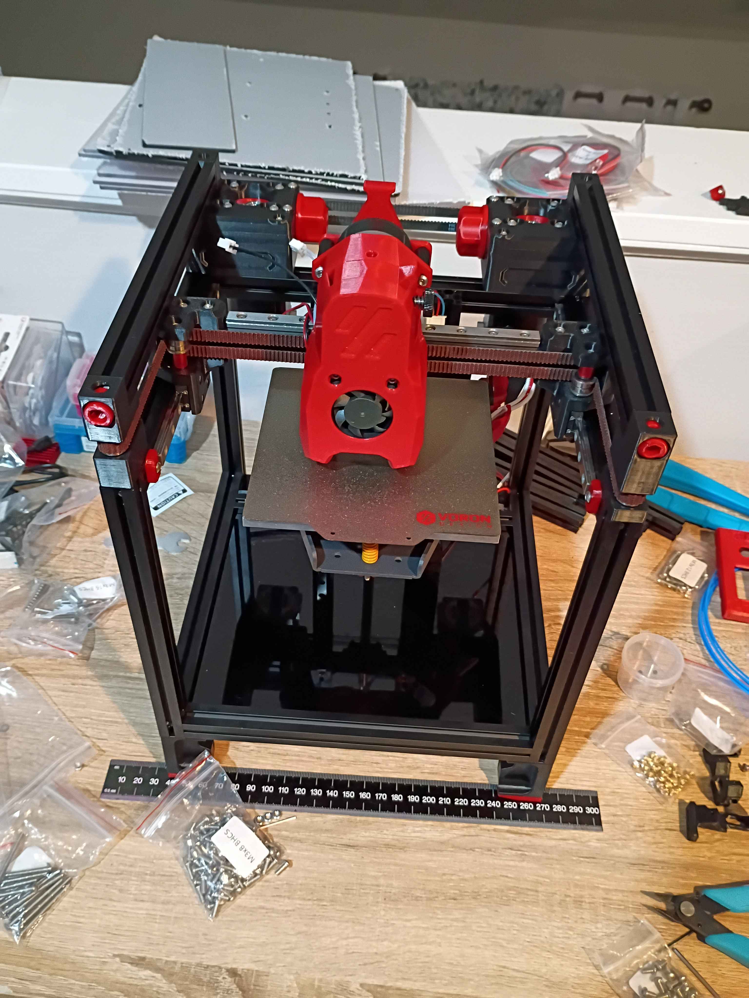
Continued to set up firmware for the Voron v0.2. Have the OS set up, and I'm just working to get the SKR Pico and OLED screen connected successfully.
Wrapped up most of the Voron 0.2 r1 build. The only thing remaining is the back panel cover (and hinge for the top hat) because I am hesitant to believe I wired (guessed) all the electronics correctly, and you can only access them from the back. Once I have the software set up and can validate that the electronics works, I will wrap up the final few operations. Also, although it's not necessary, I'd like to add more screws to the z-axis linear rails and upgrade the part cooling fans if not the entire hot-end system, but those can wait until after the printer is working and mostly tuned in, likely later this week. 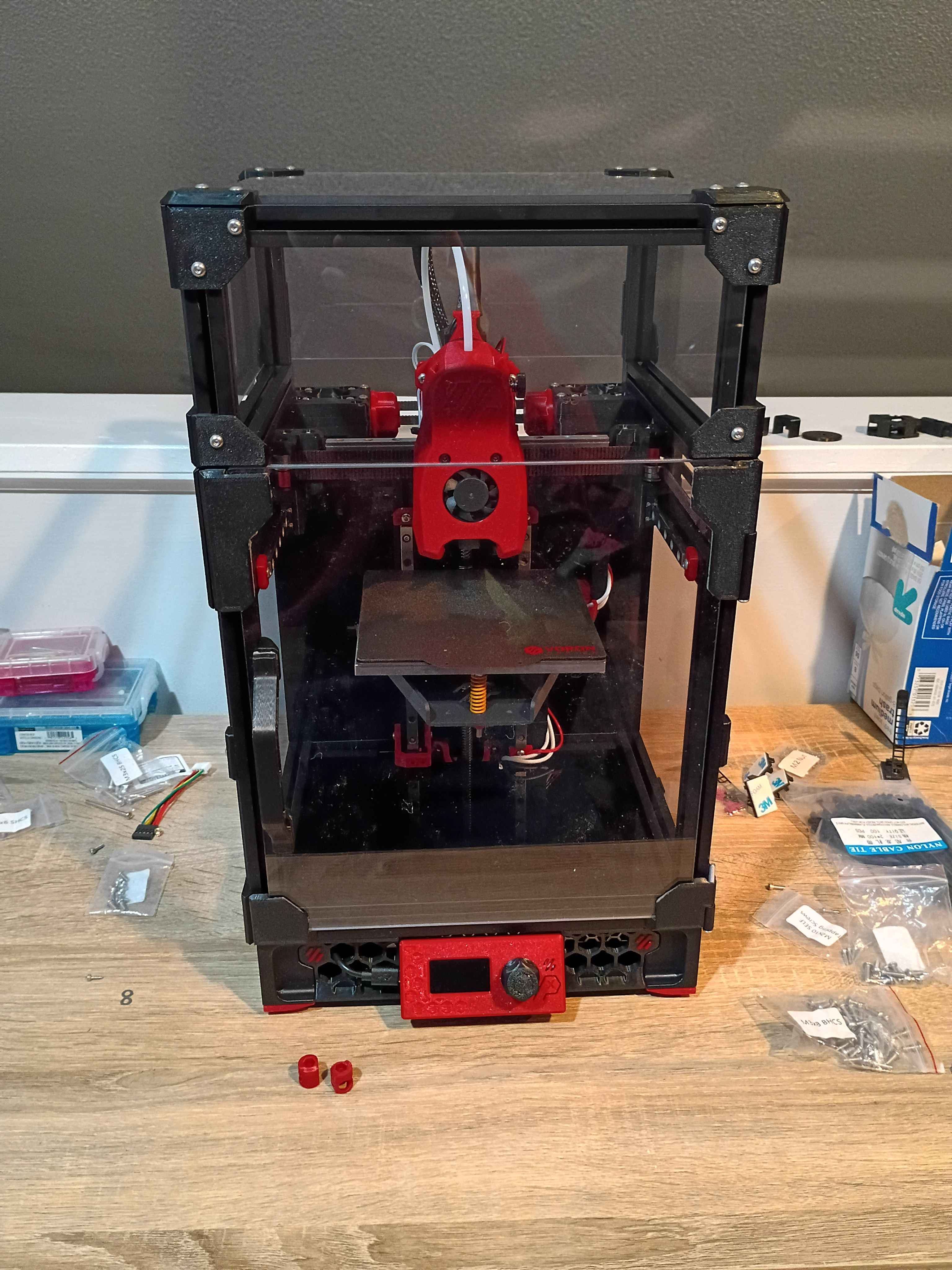
Continued to work on the Voron 0.2r1 kit. Completed most of the frame, motion system, and toolhead. Probably only 1 more day. 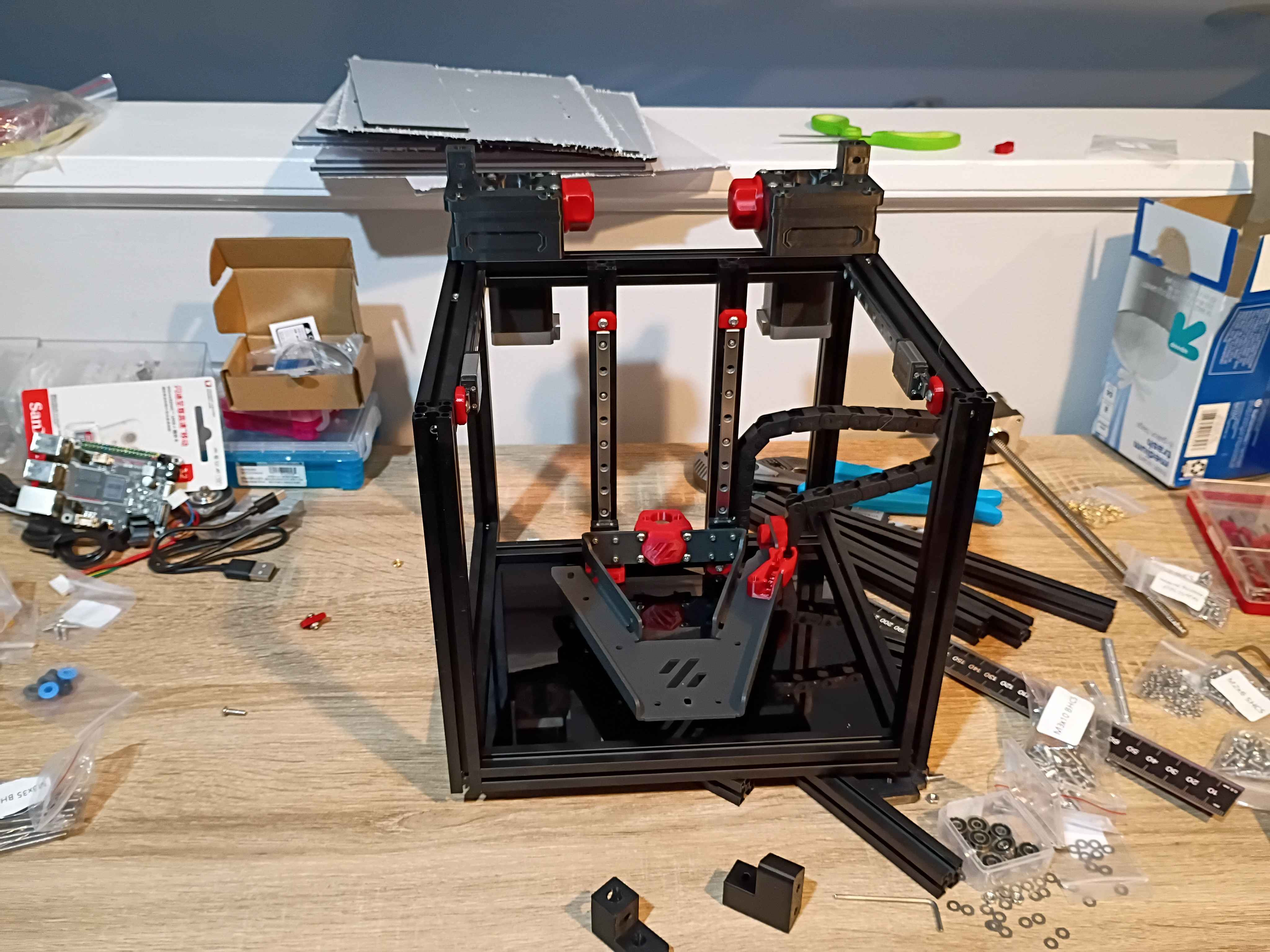
Started kit build of Voron 0.2r1. 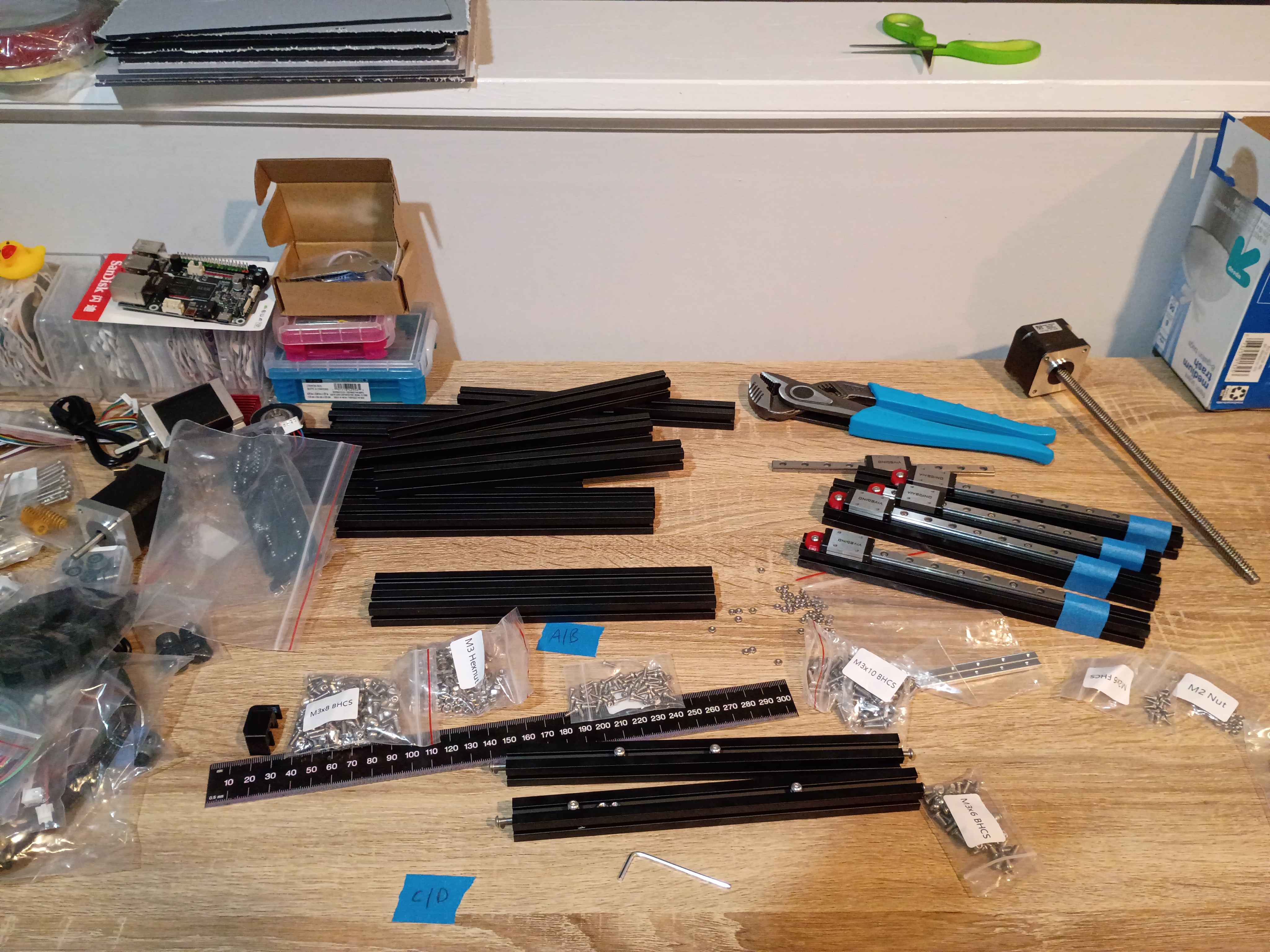
Laser cut around 30 finger-spacers. 20% power 20% current are decent settings for engraving the surface of plywood. Customer was satisfied. 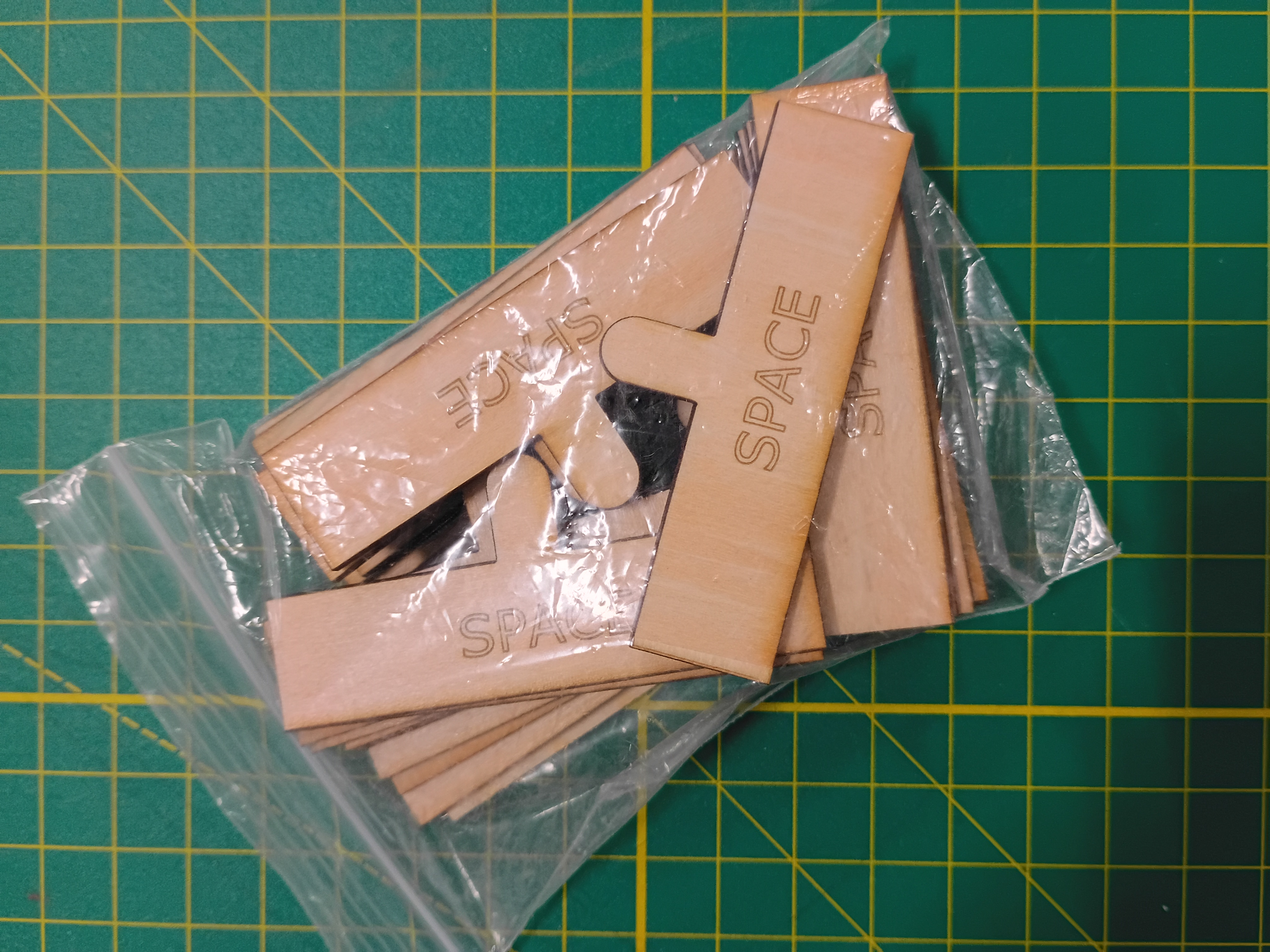
Created an SVG path for a finger-spacer tool to be laser cut. It helps children leave a space between words when they write. 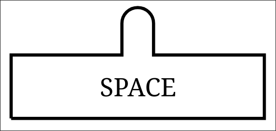
Got some exposure to laser cutting on the Muse3D at work. Made some personal engravings and tested various power setting and cut speeds. At 100% power even 100% speed is enough to cut thru 1/8-inch plywood.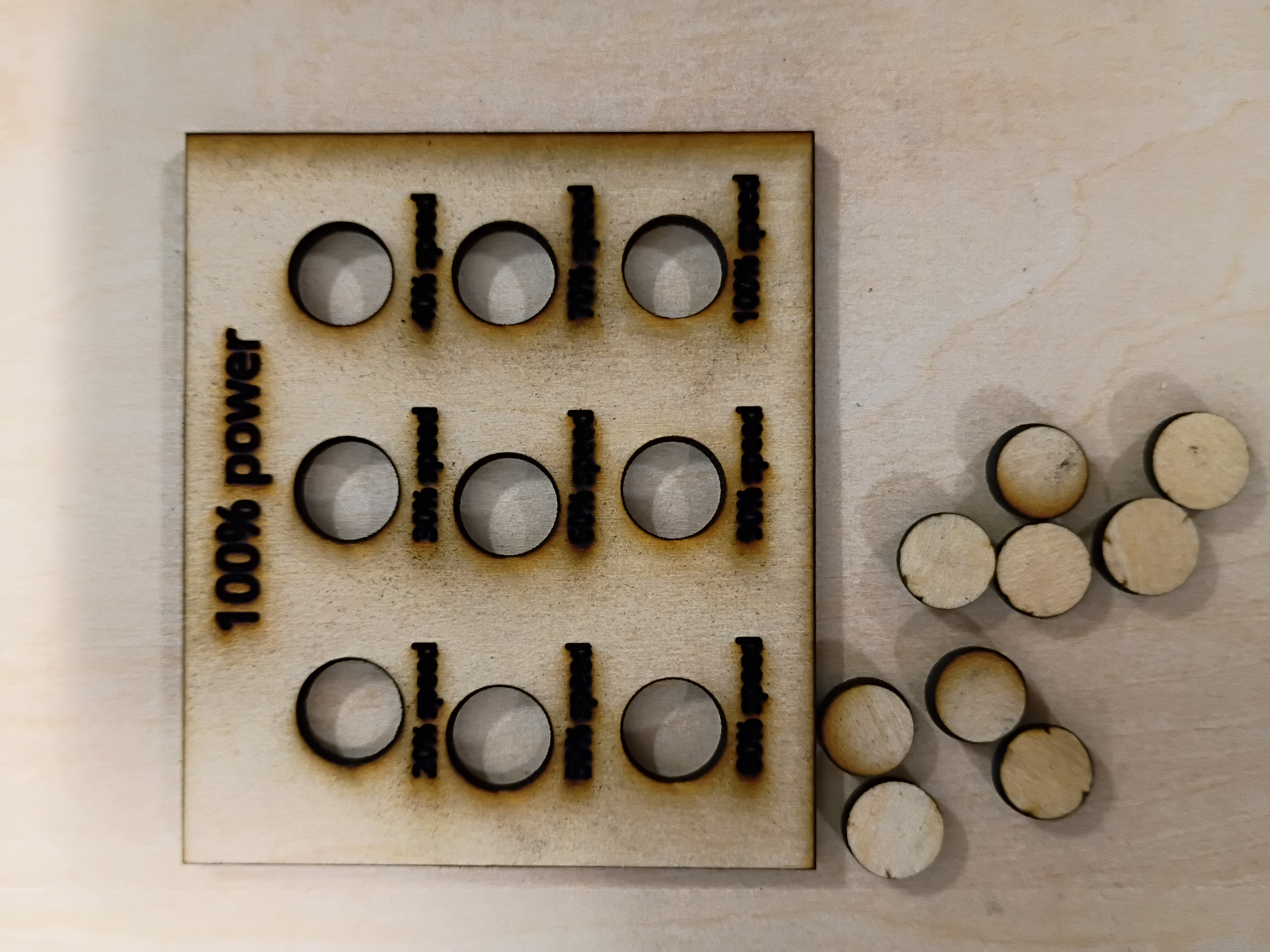