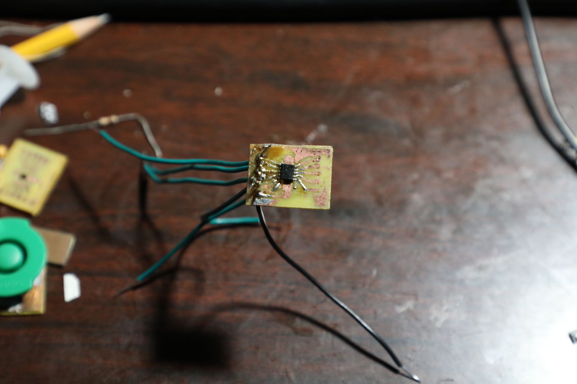
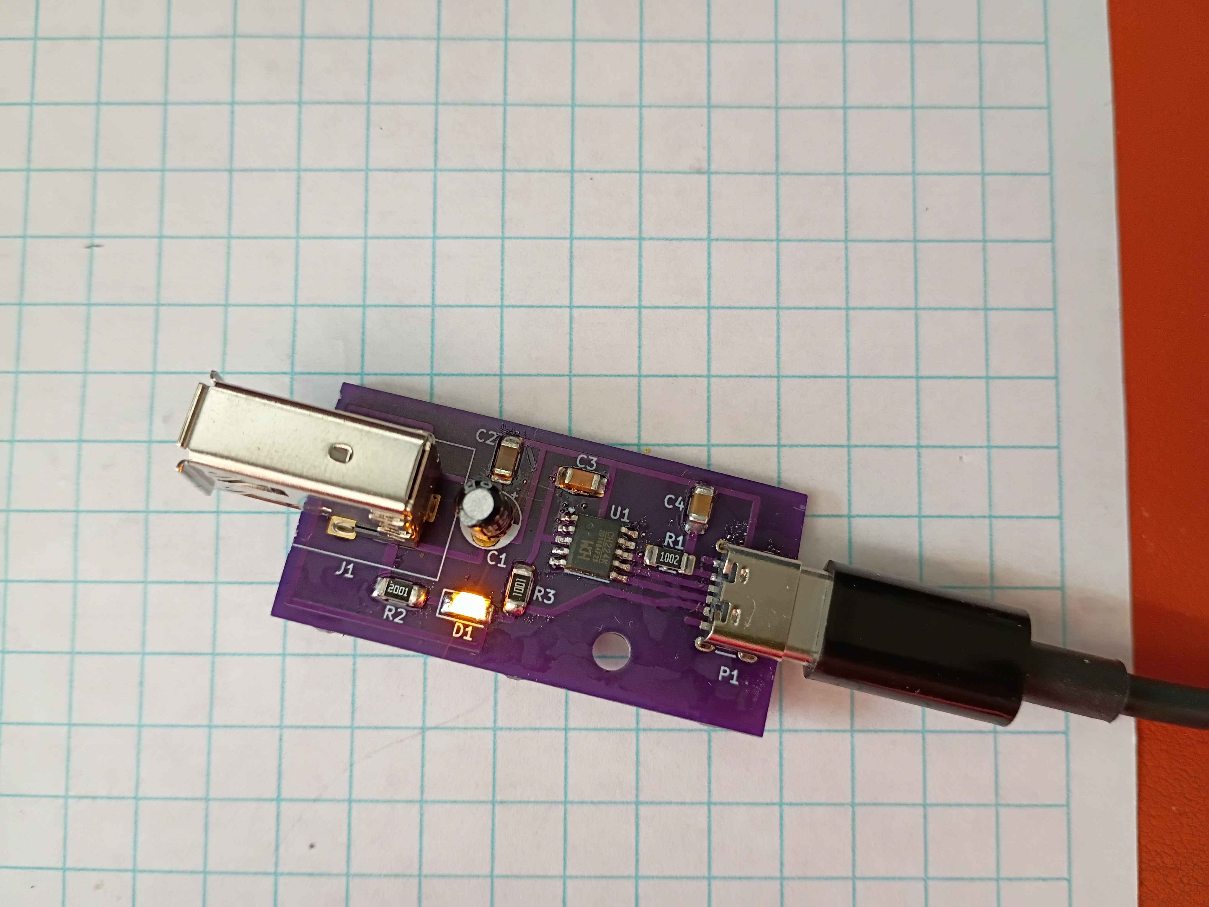
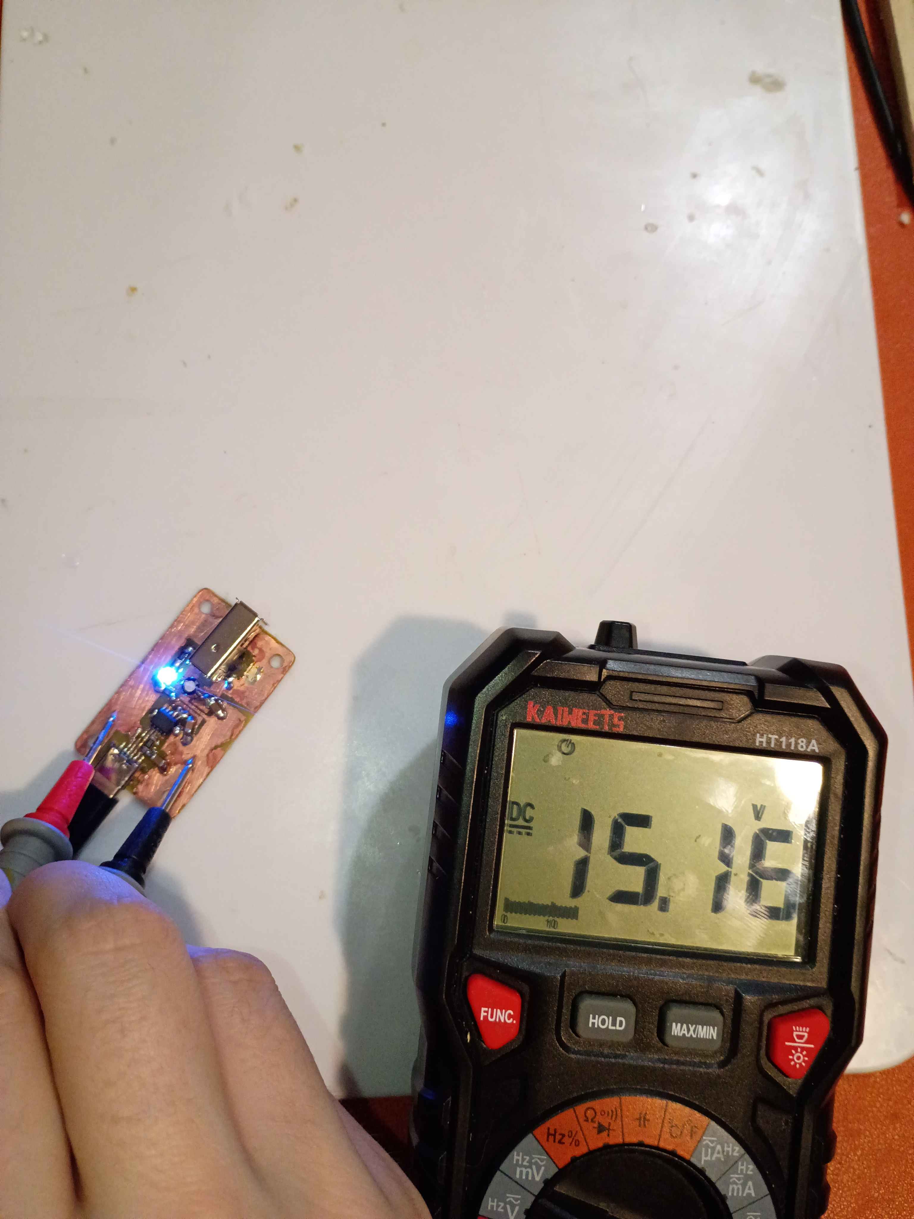
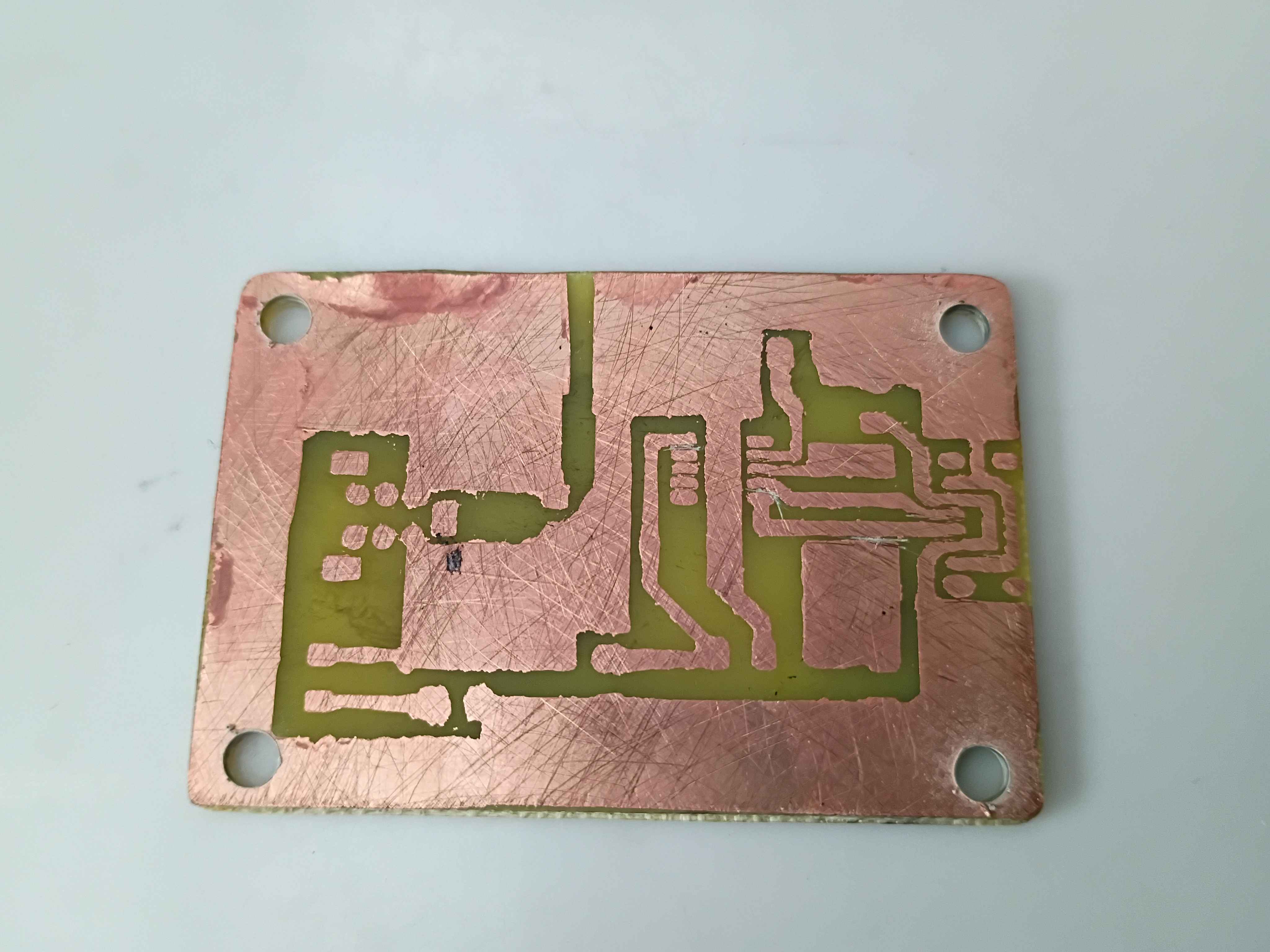
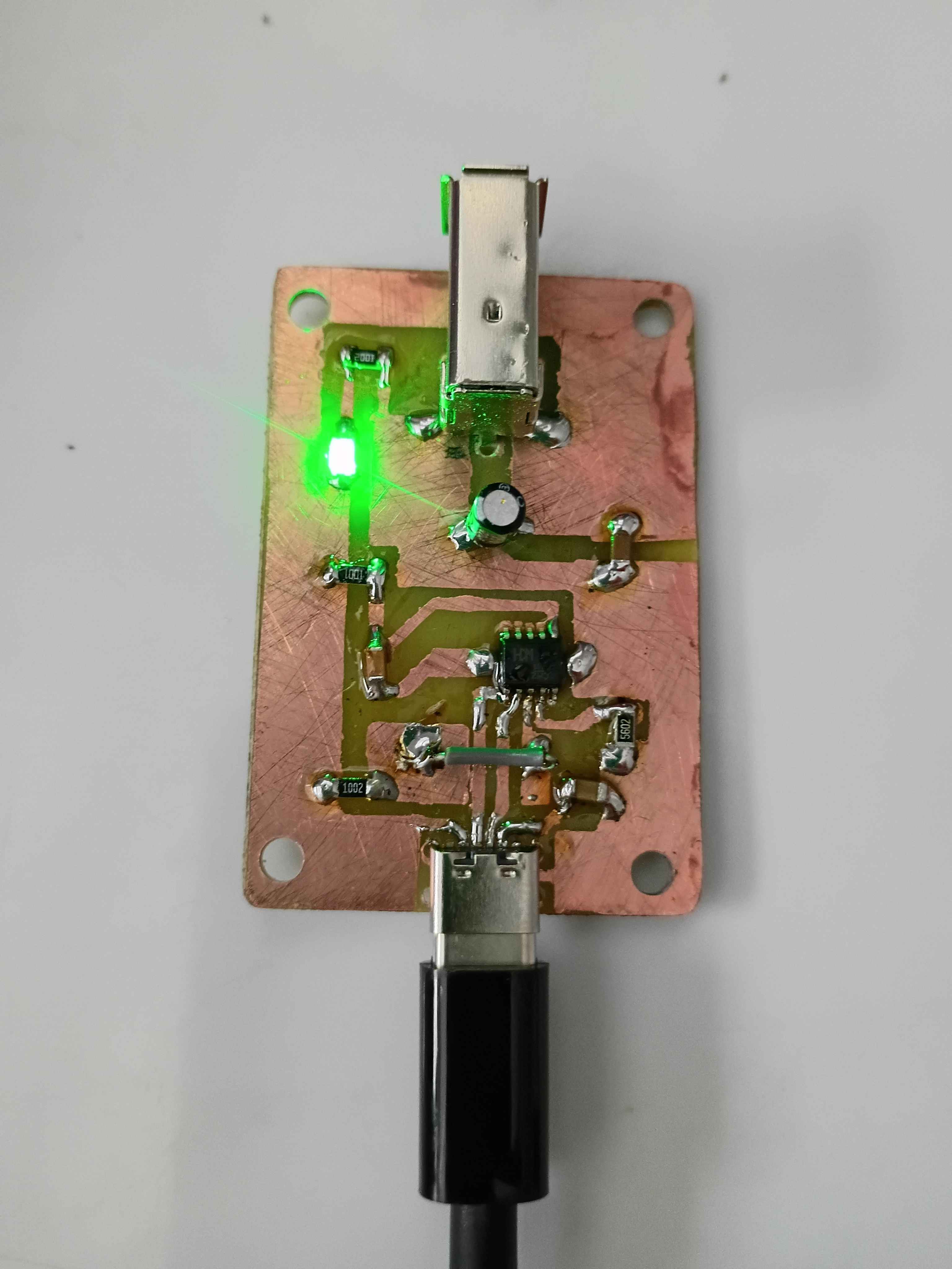
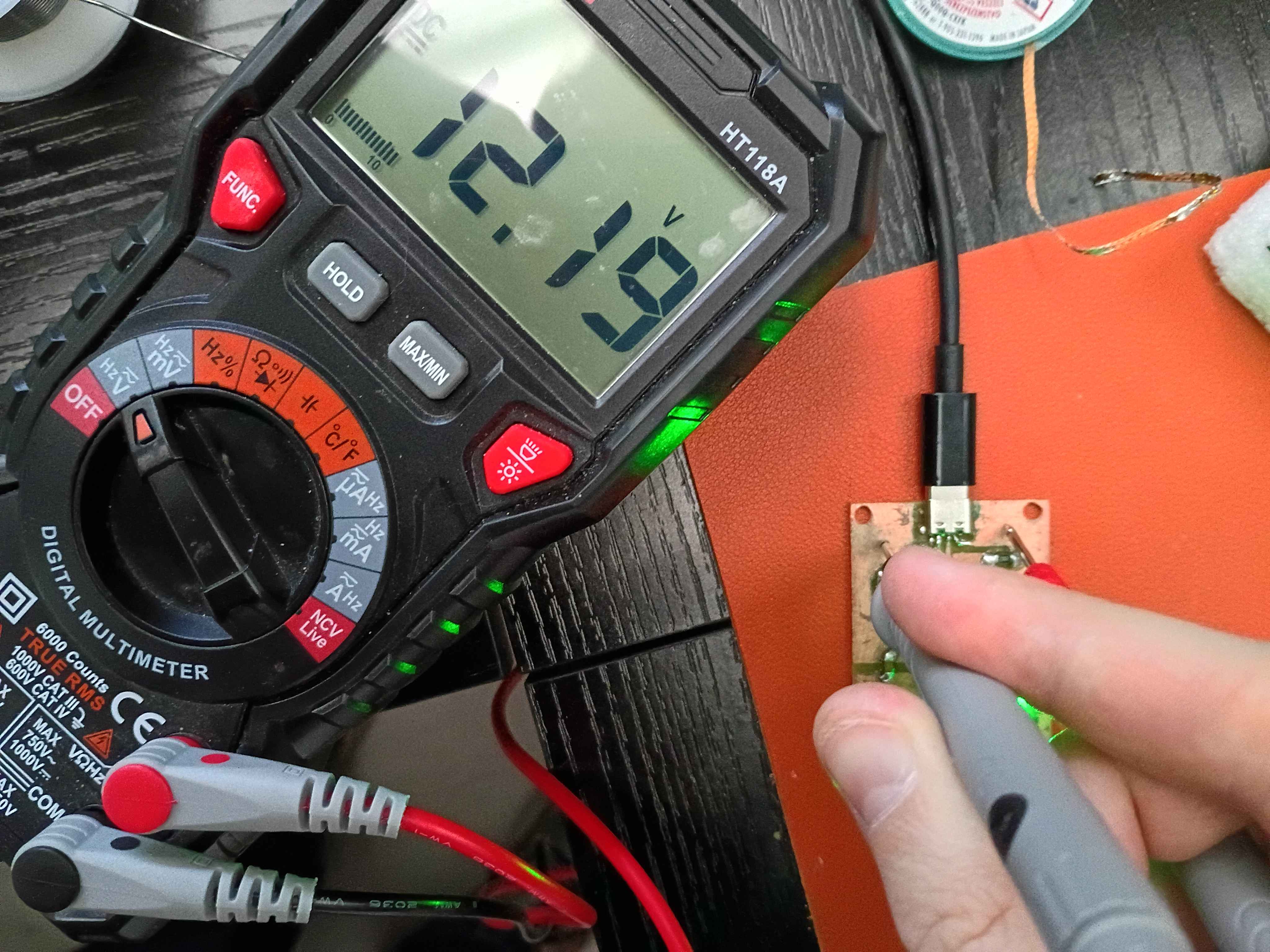
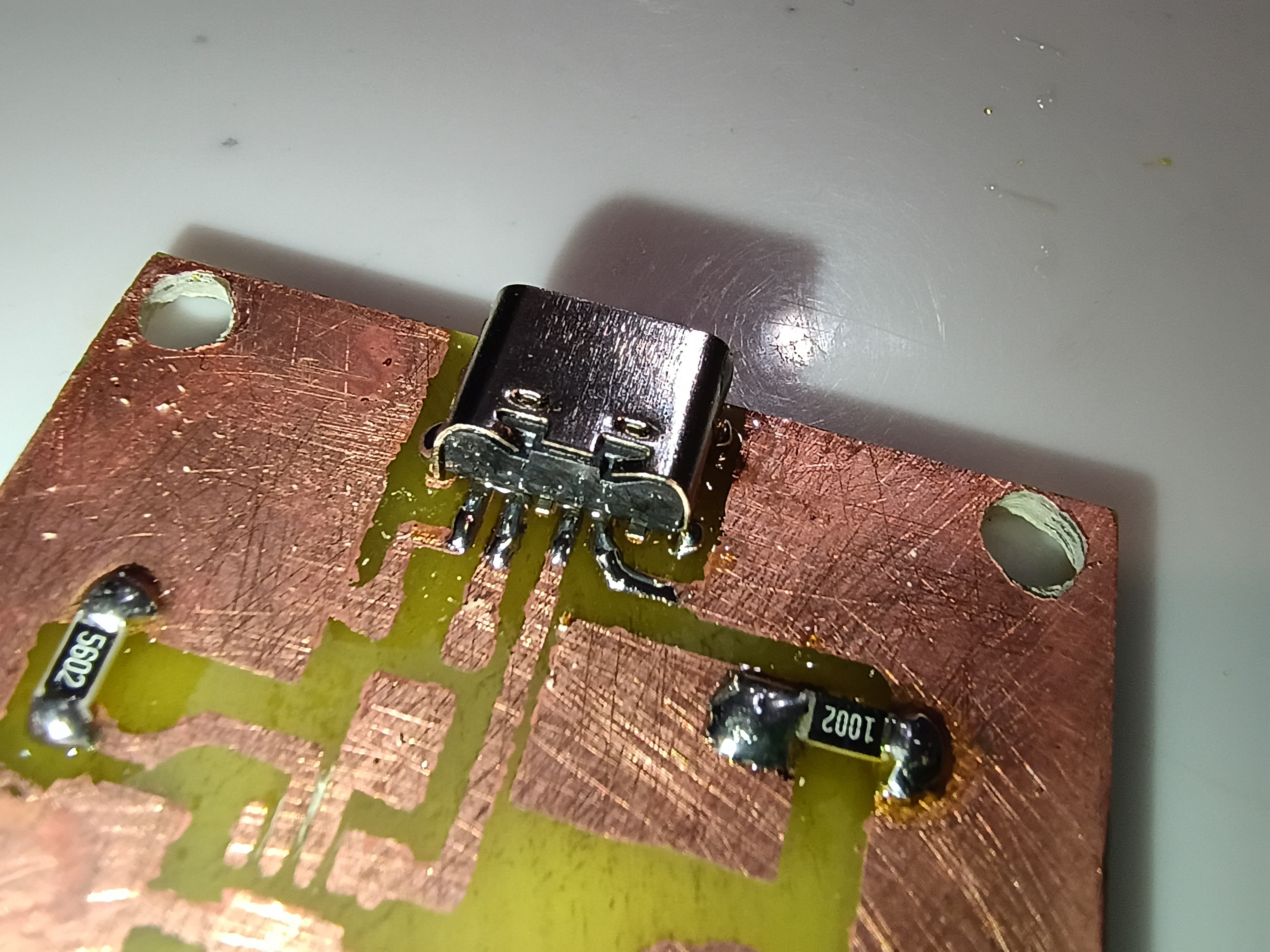
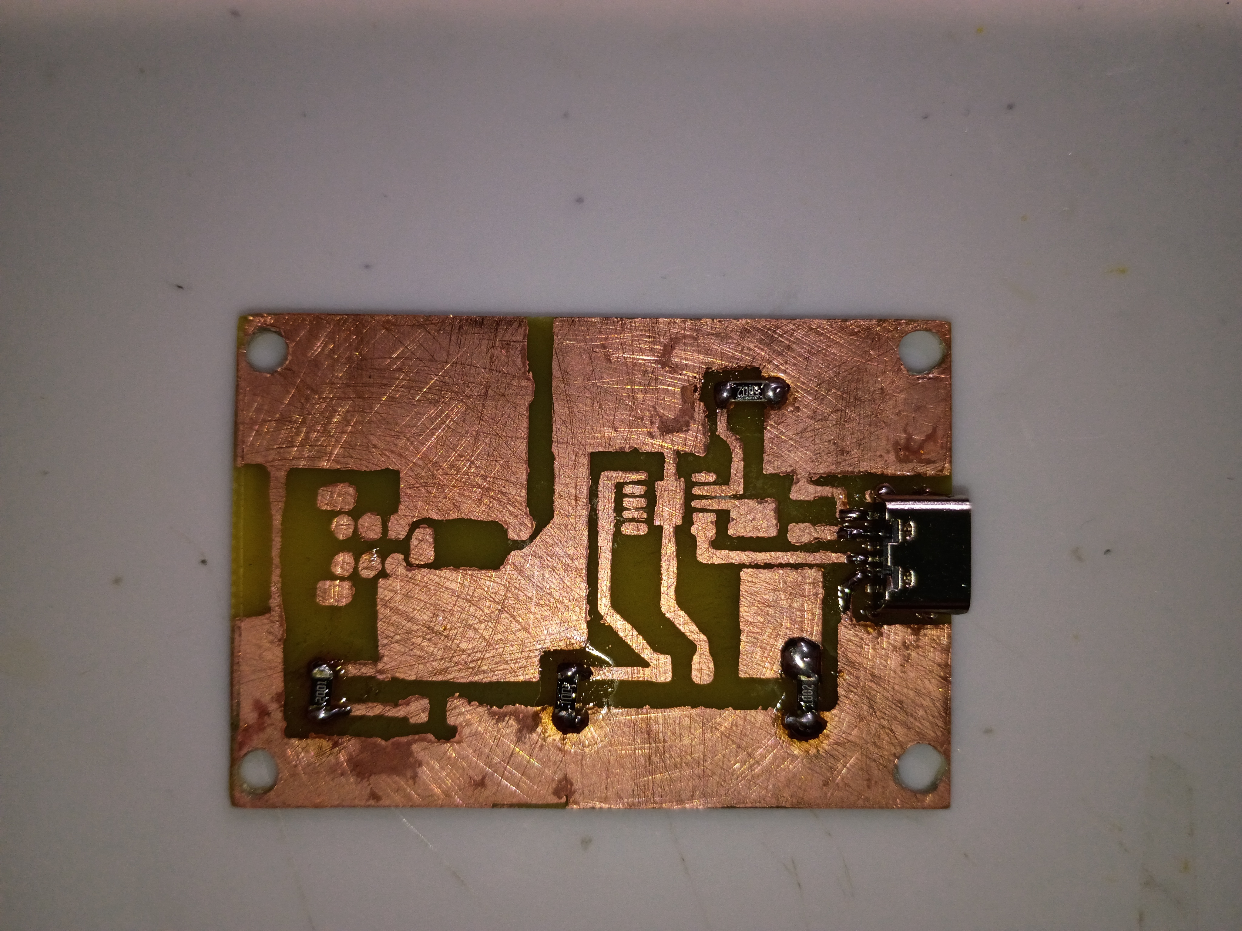
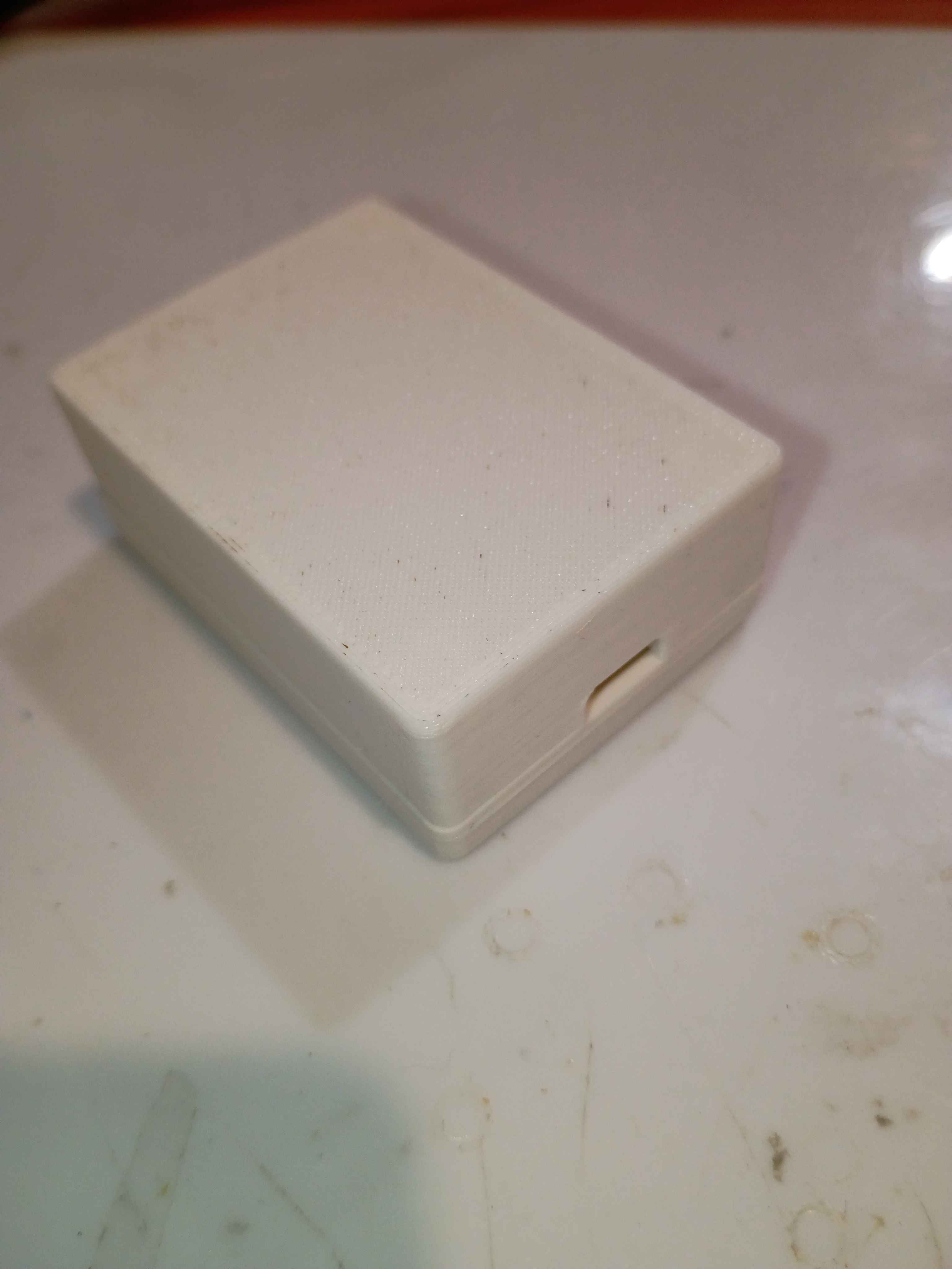
Manufactured the CH224K Breakout. It's mostly finished. The connections have been tested with a multimeter and are sound. The PCB was etched with ferric chloride and then drilled. The CH224K was then soldered to the Board.
Created GitHub landing page for project with BOM, photos, and links.
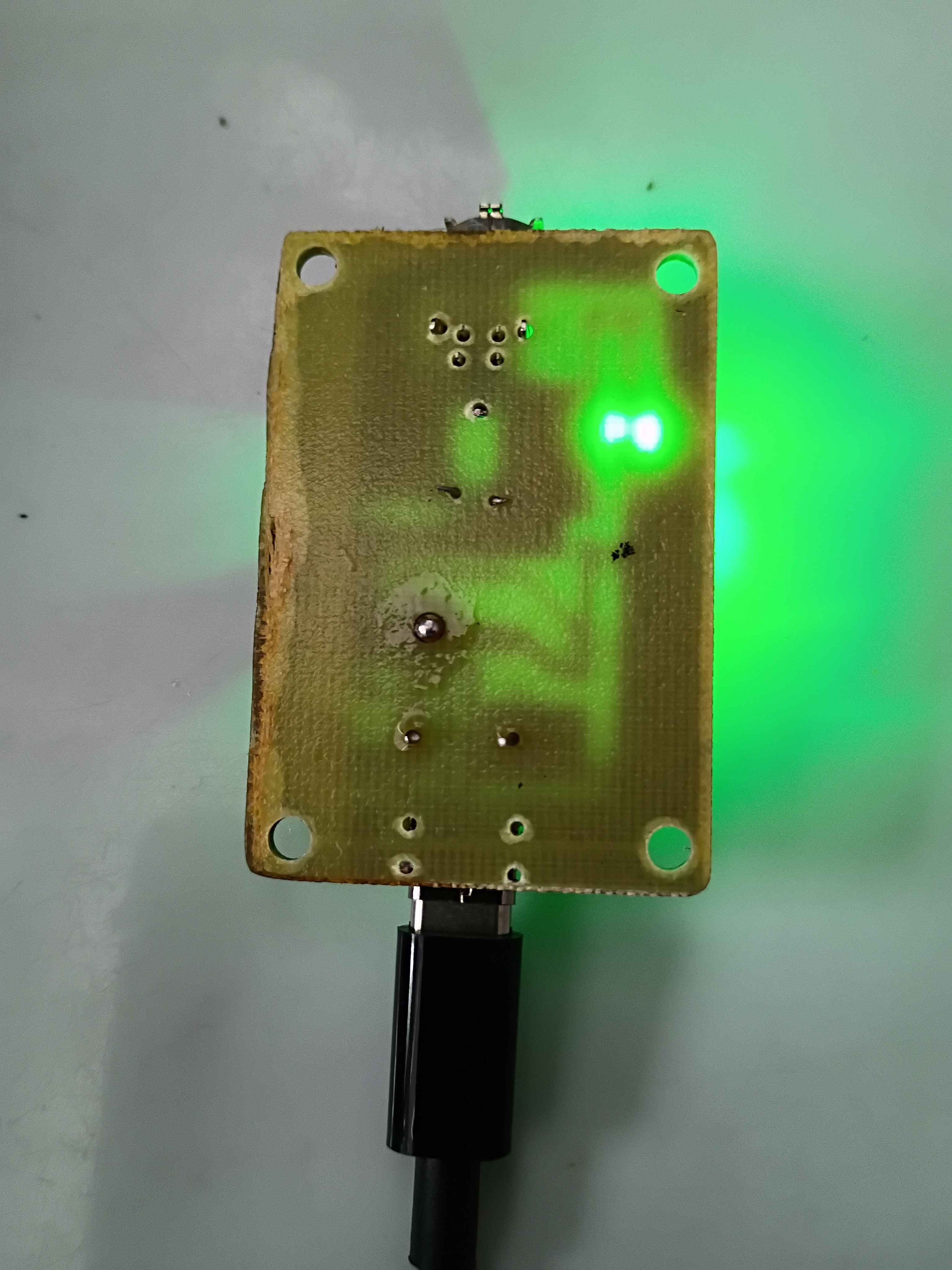
Made progress on the ch224k breakout pcb. 1 was successful and 2 failed. I believe the first succeeded because it was allowed to cool off before submerged in water. 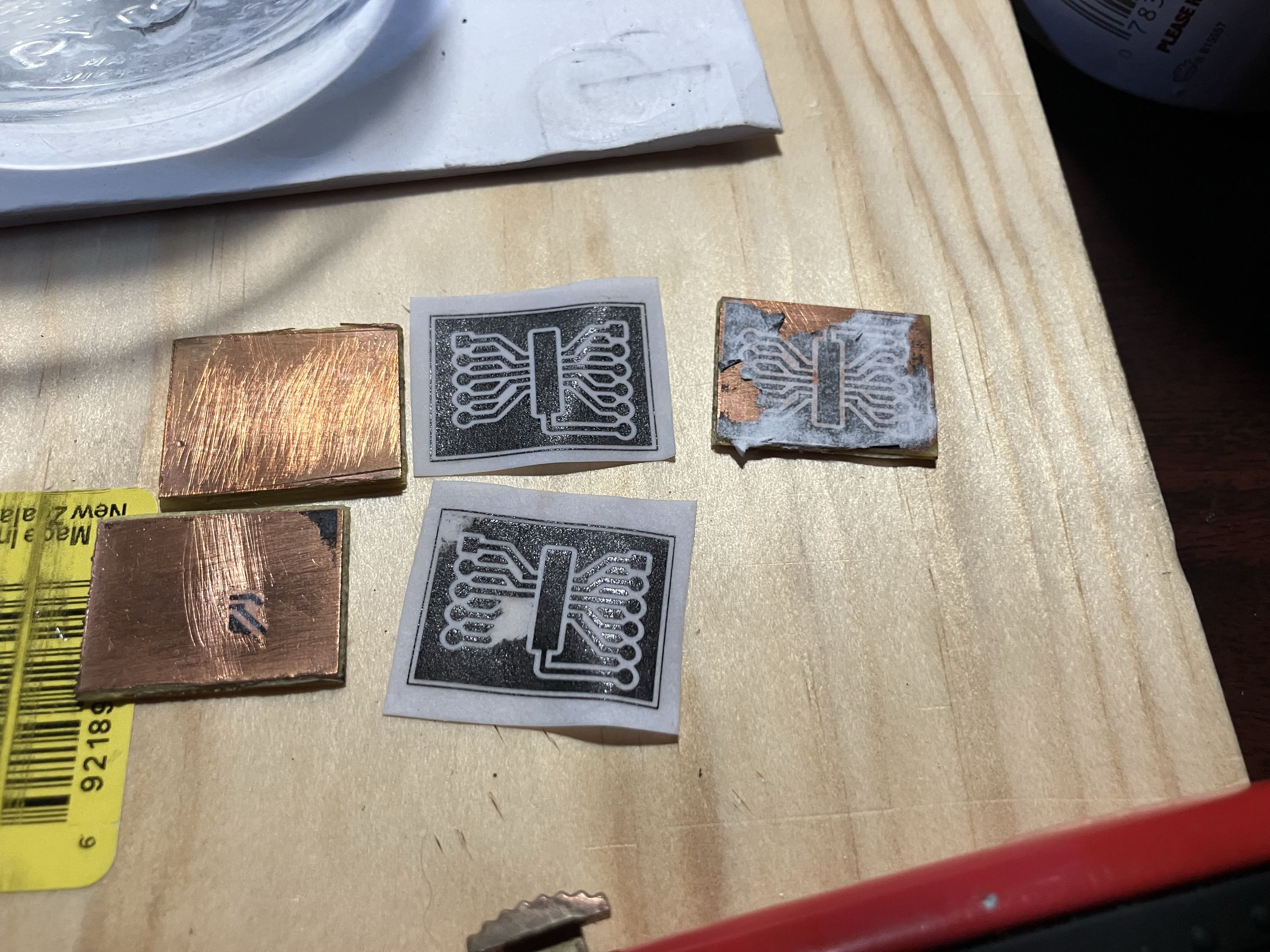
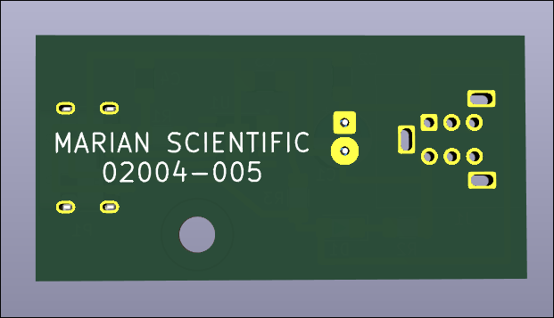
Revised PCB (02004-005-A) with some final lessons learned including test pads, extra exposed copper on the USB-C for solder mounting structure & component labels. 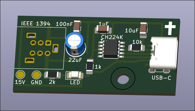
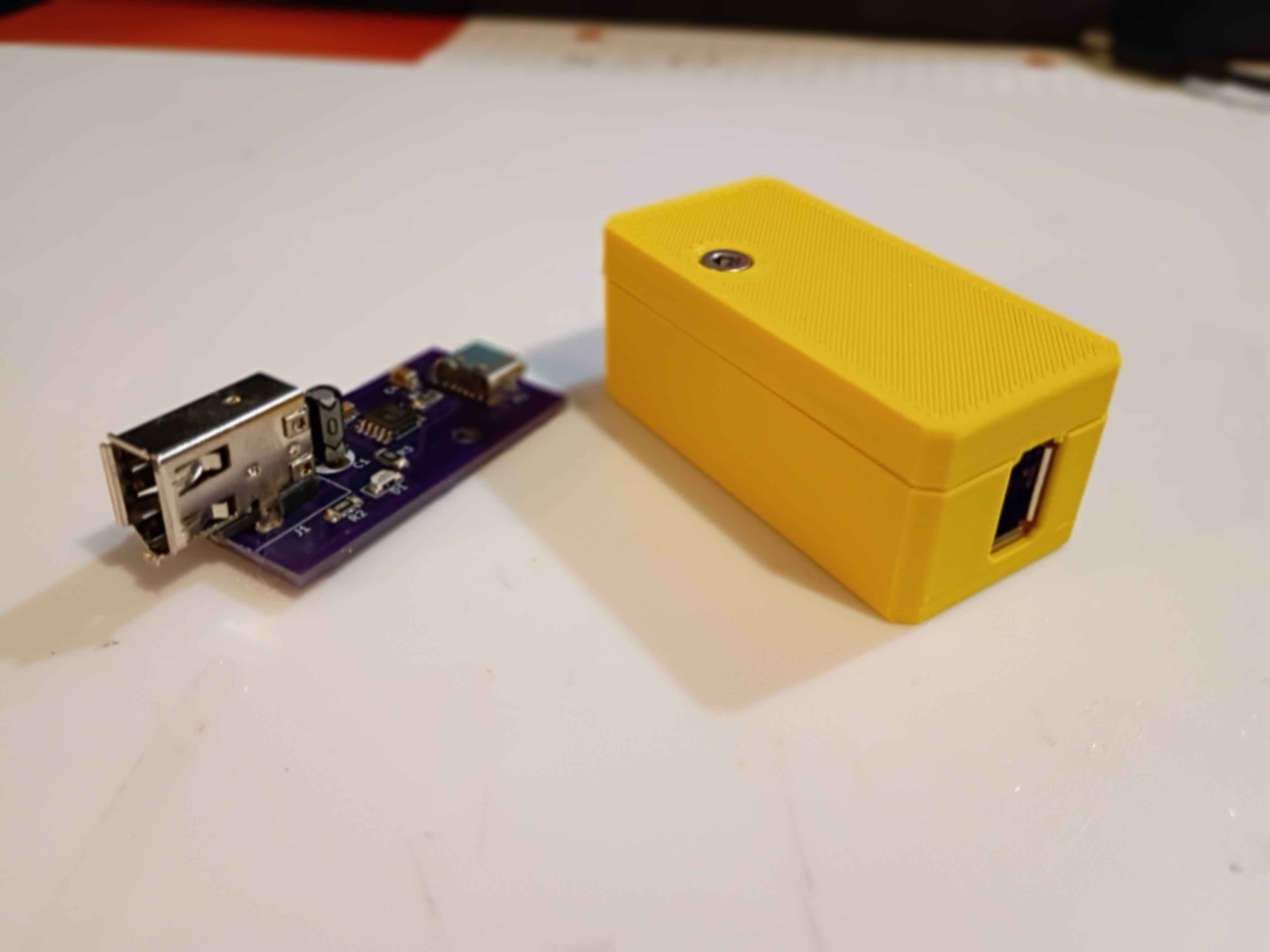
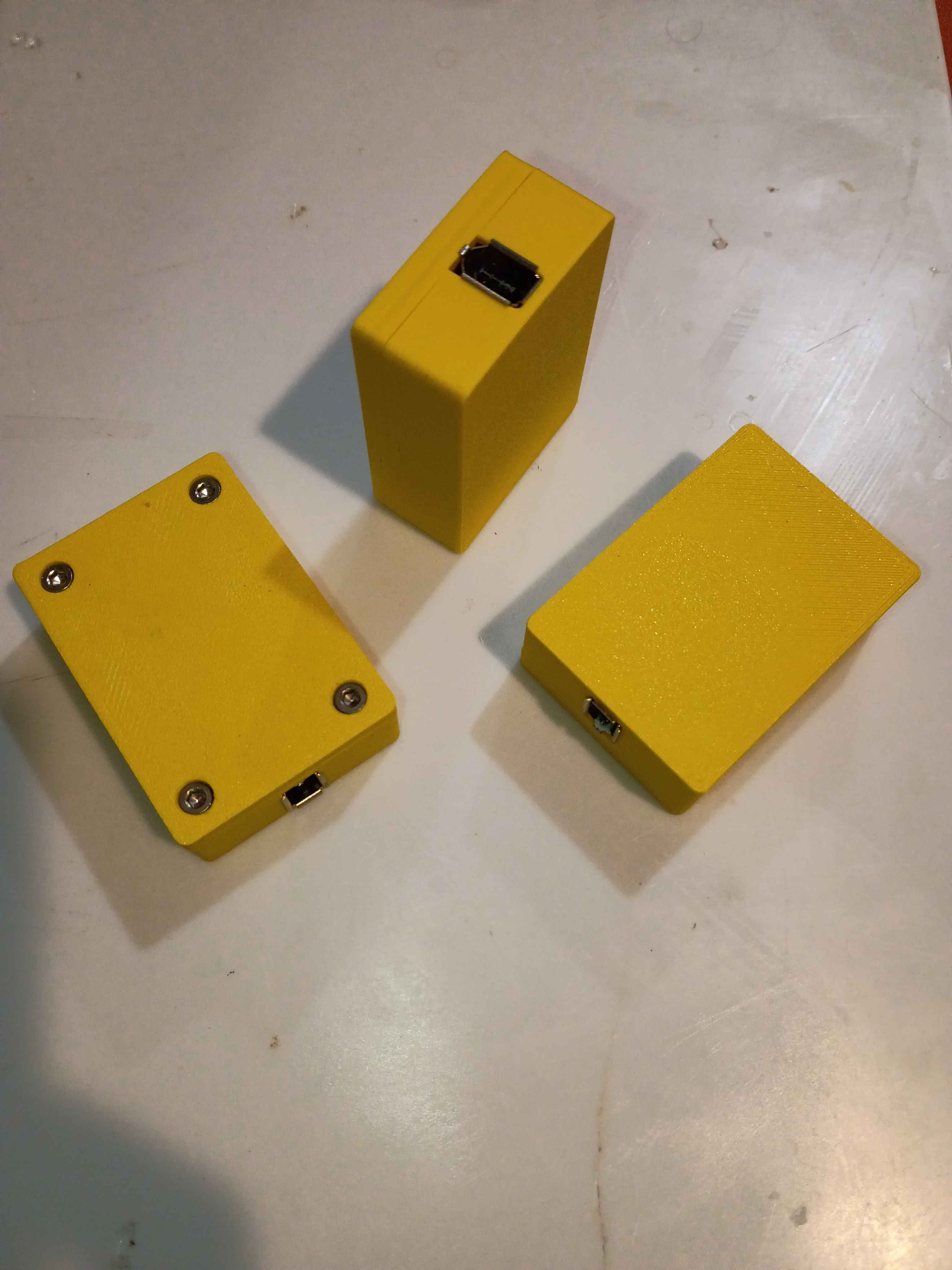
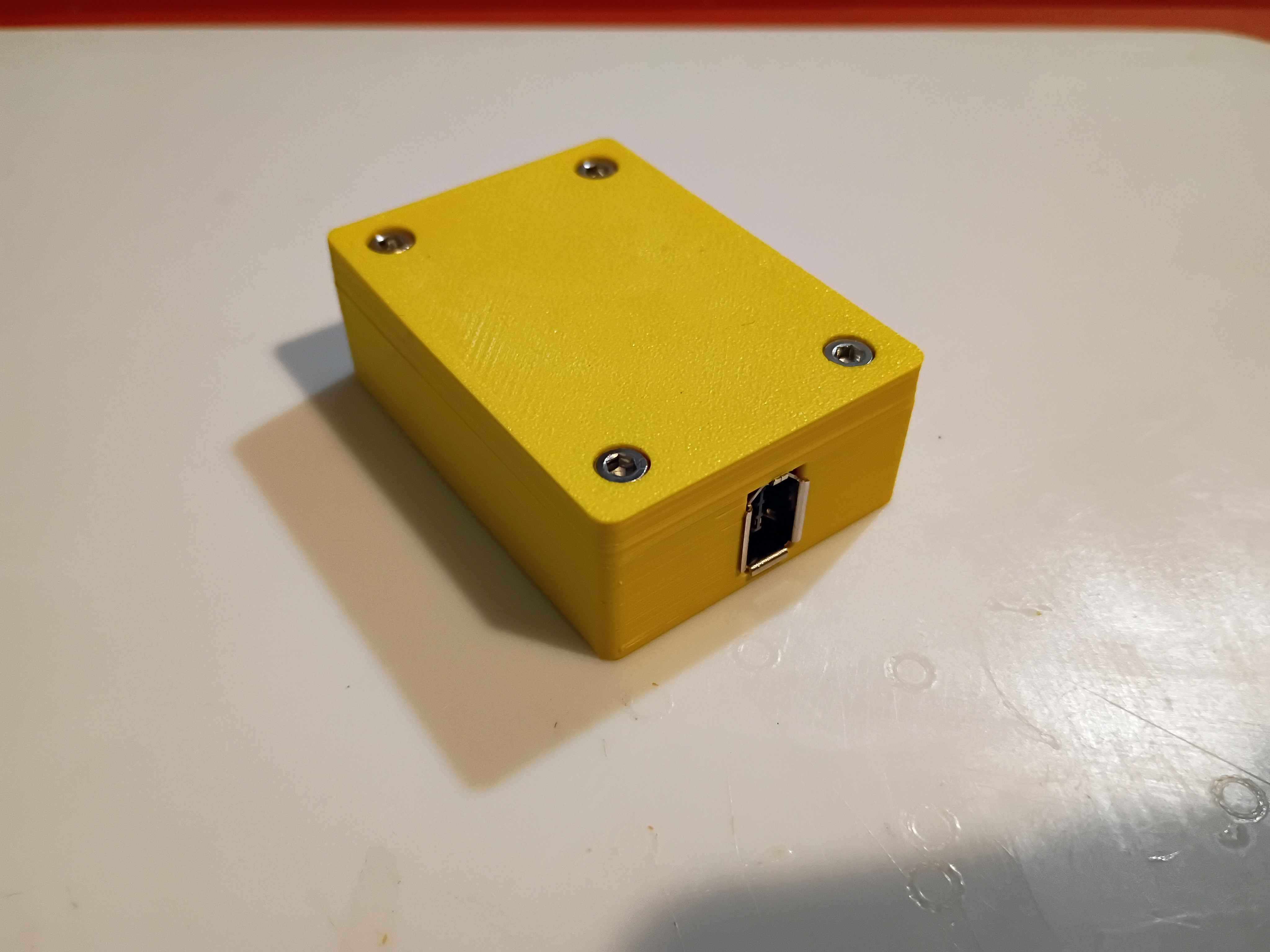
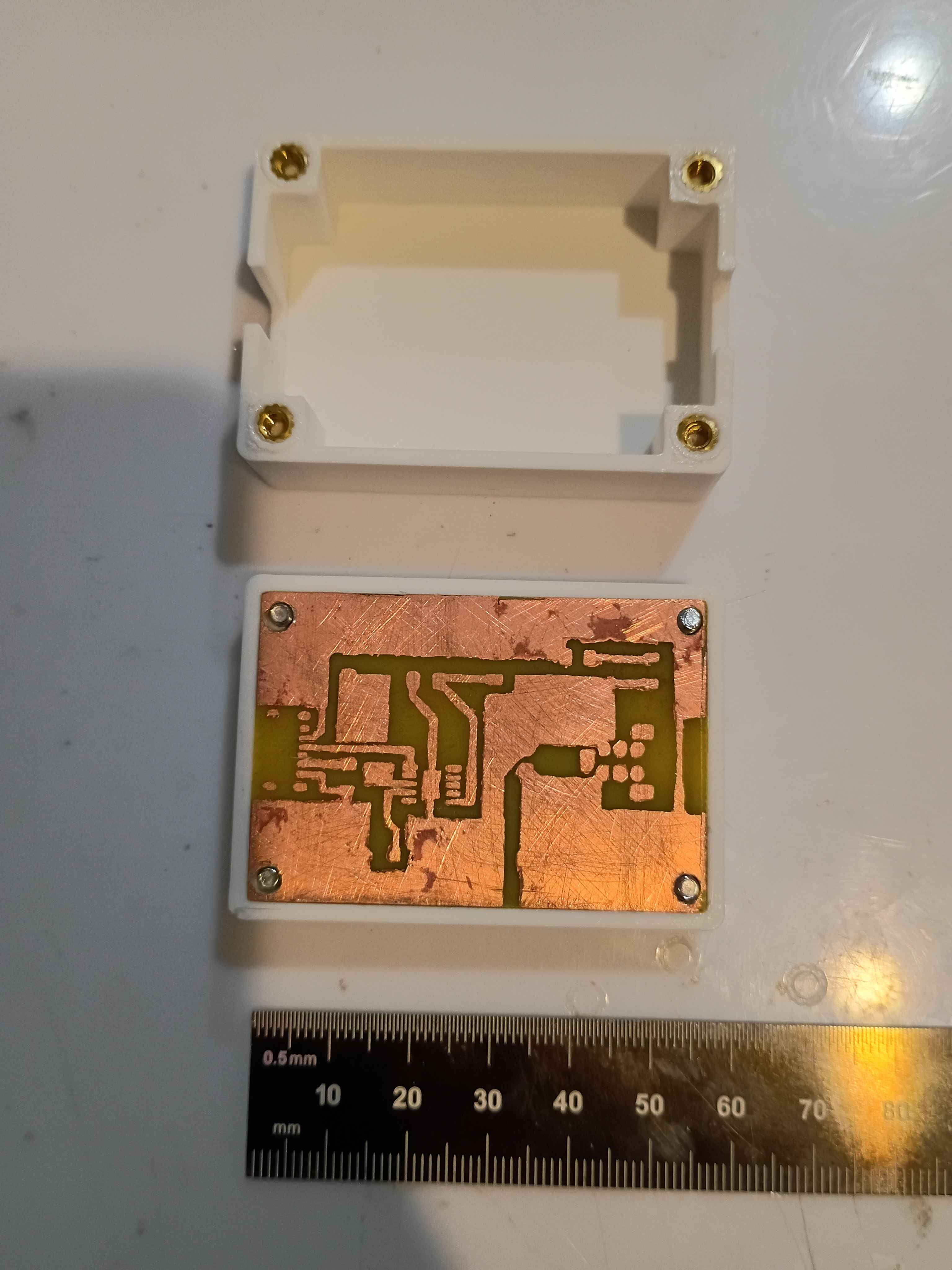
Redesigned 02004-007/008 assembly for the final time and printed 2 copies of each. Installed the 02004-005 PCBs. They actually work surprisingly well, though there is still a slight seam visible between them. 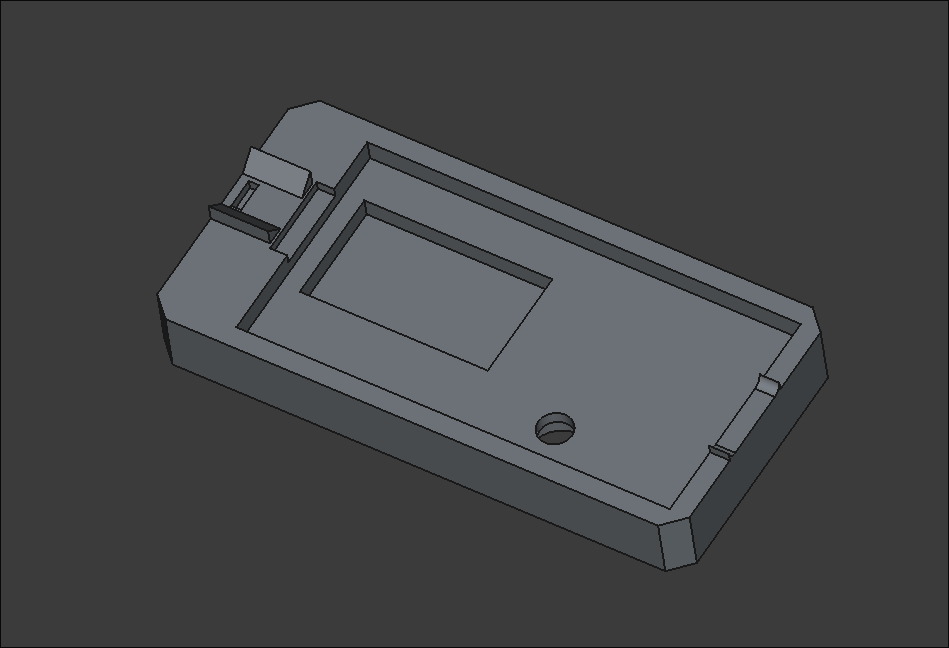
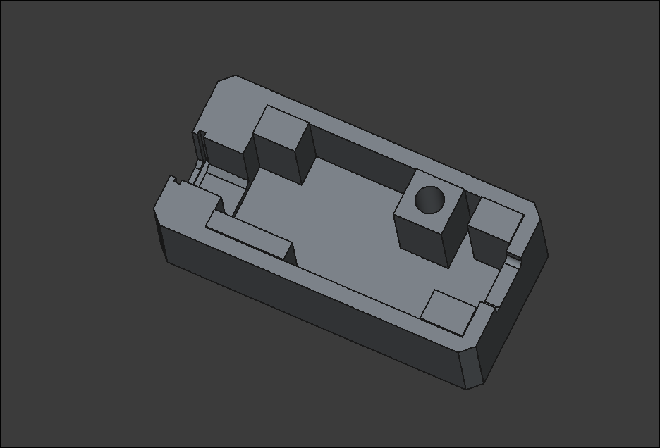
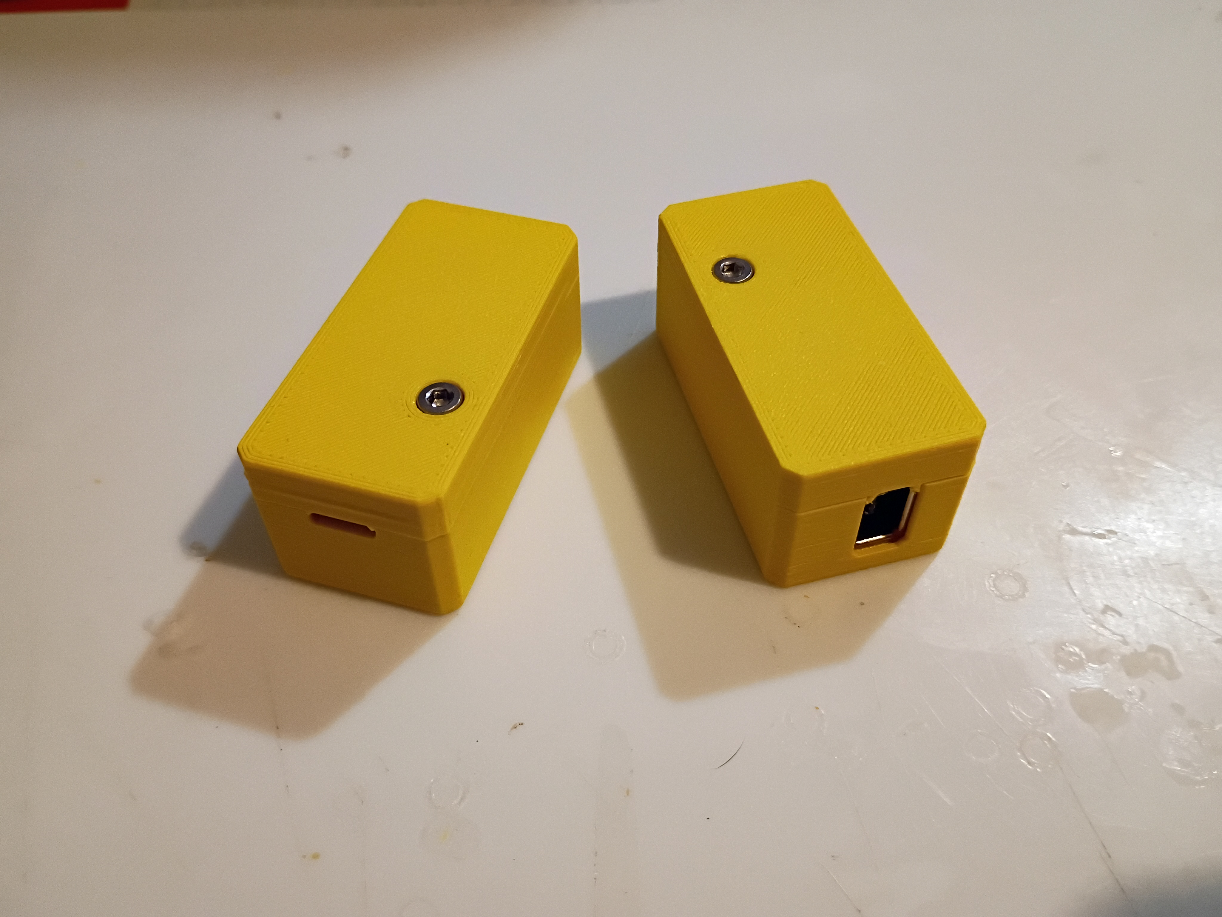
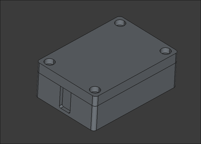
Added a dab of CA glue to the FireWire and USBC thru hole contacts for additional support. Revised and reprinted two iterations of the housing assembly out of ASA. I think I need one final reprint of the smaller piece with a slightly deeper recess. 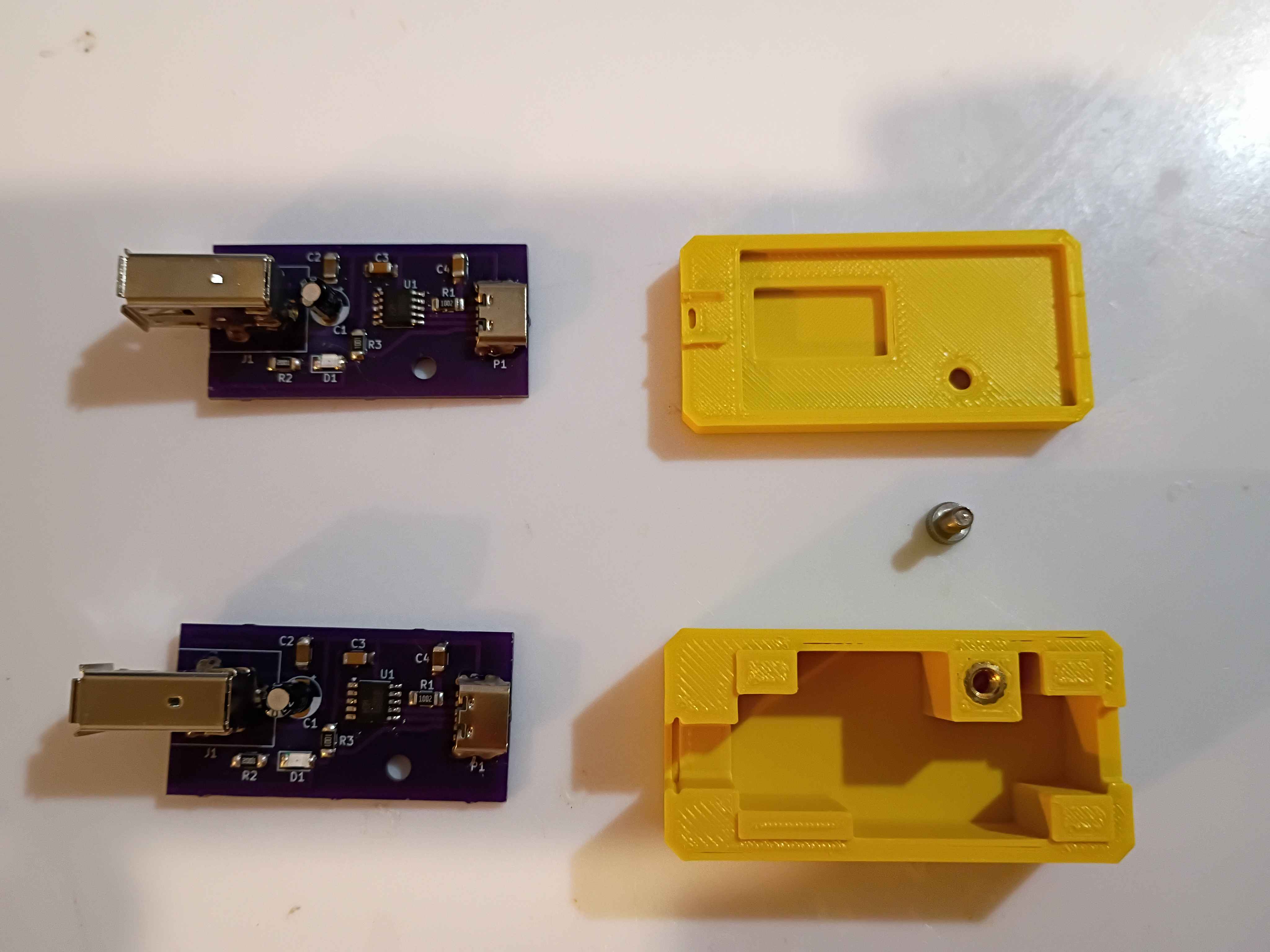
Successfully soldered and tested 2 more boards. Redesigned the housing based on lessons learned from the first box prototype yesterday. Parts are printing overnight, and the assembly will be tested tomorrow. 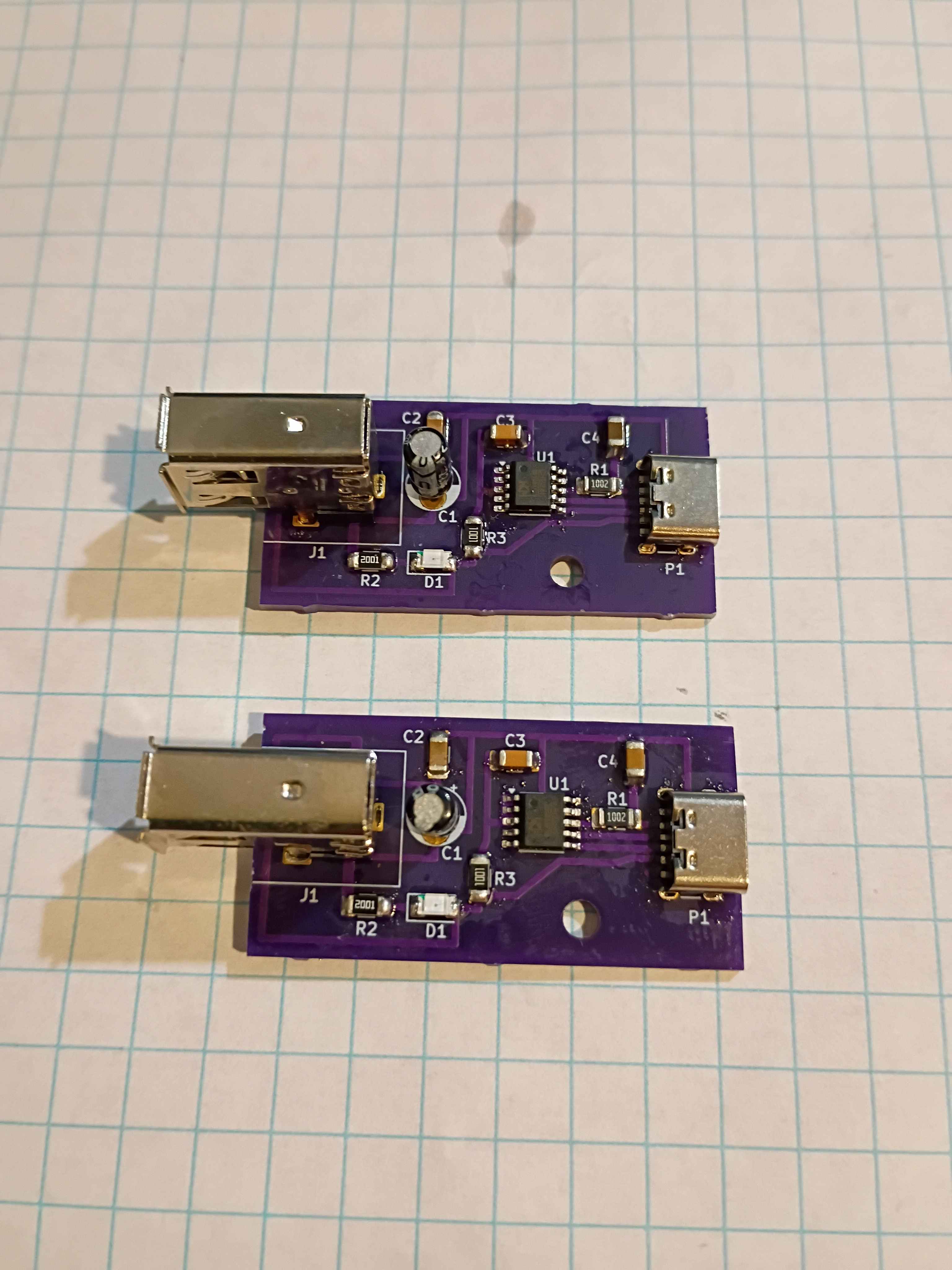
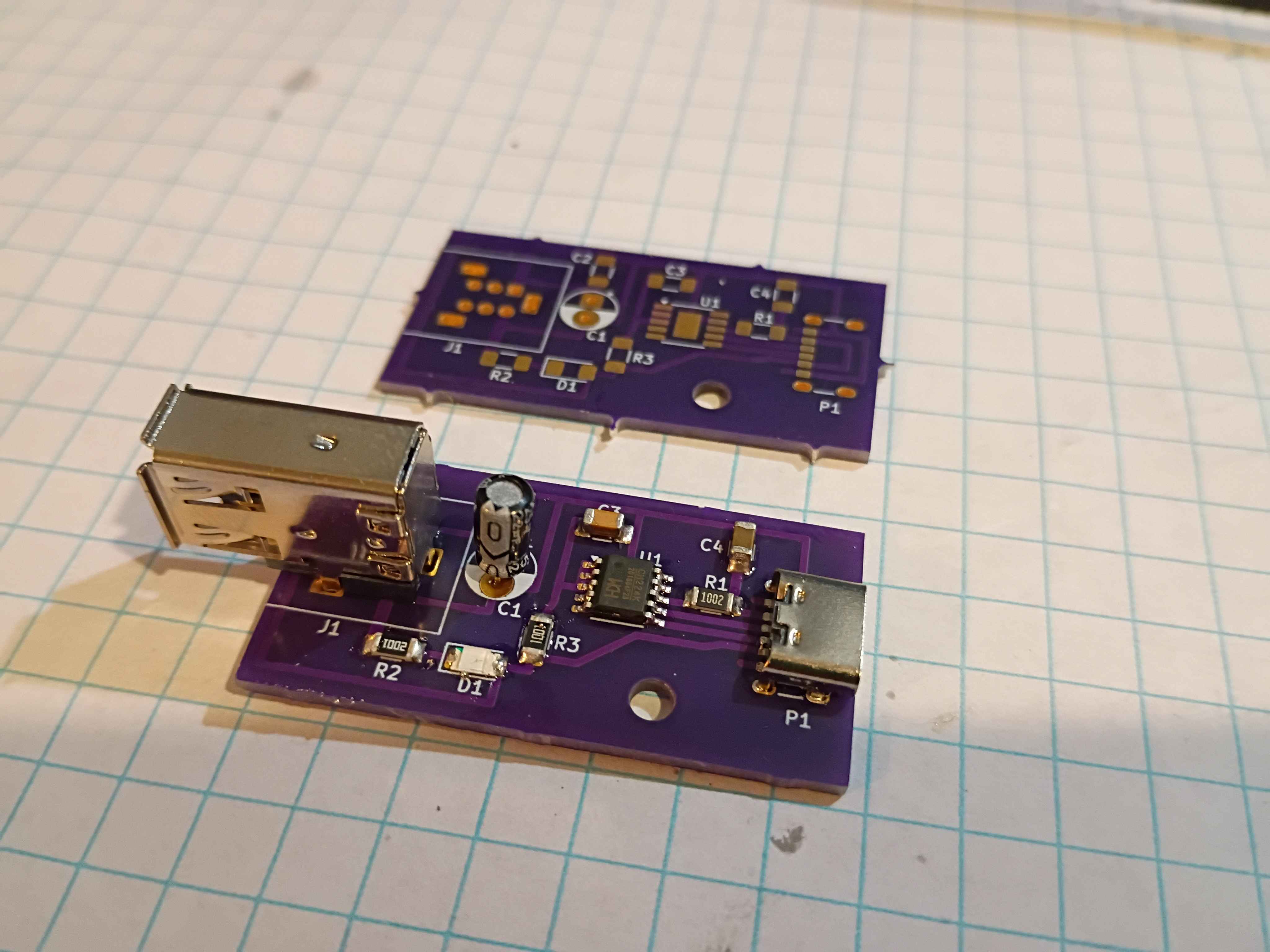
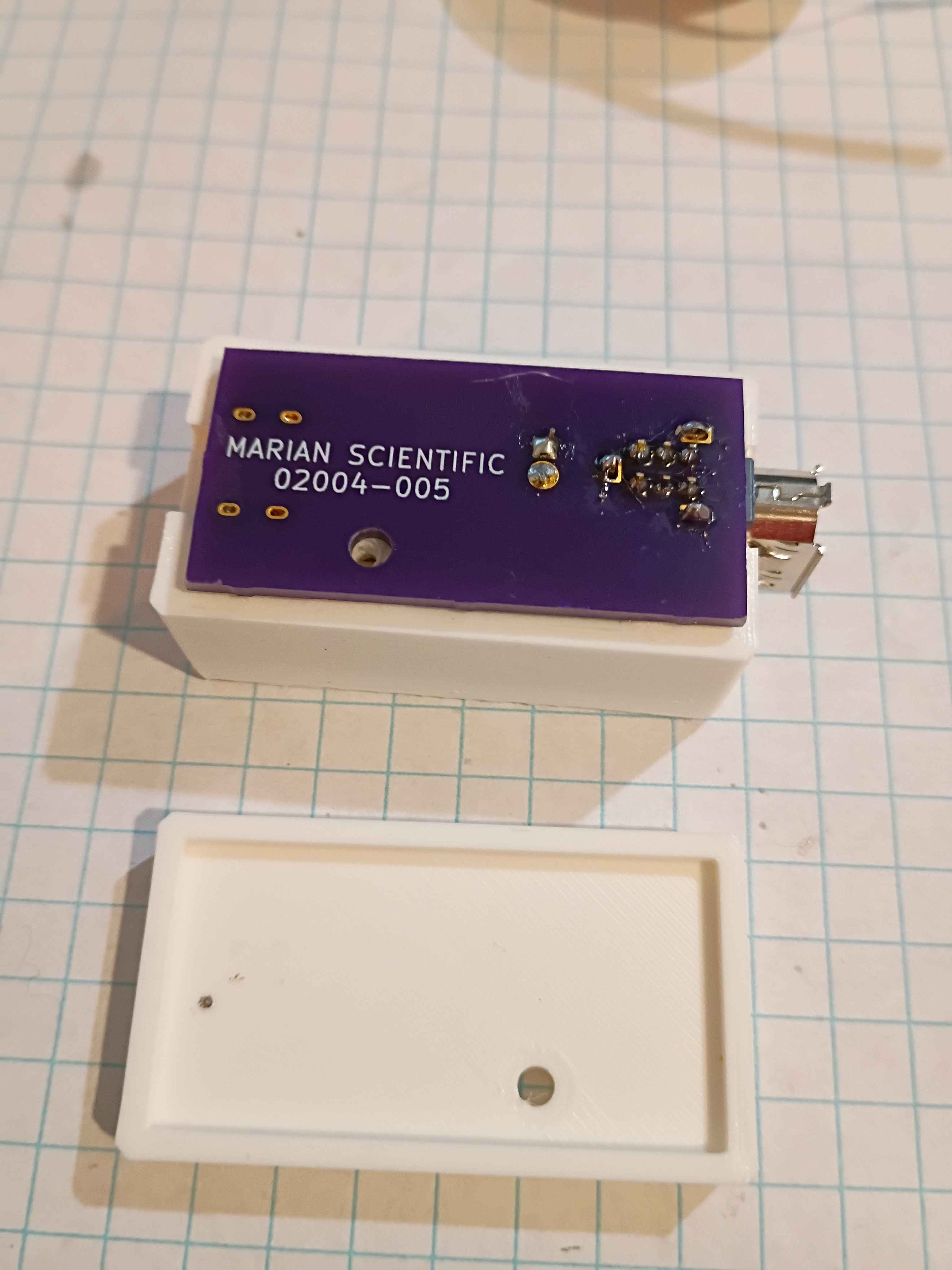
Received 02004-005 PCBs from OSHPark. High quality, as usual, but took 7 business days, with the fastest processing and 2-day shipping, plus 2 weekends. Still good in a pinch, I suppose. Designed and printed a 2-piece housing, though several details will need to change before it works perfectly. Used hot plate for the first time to solder most of the components, which went pretty well, and did the FireWire and thru-hole capacitor by hand. I think some components (including CH224K) were shorted because I put too much solder paste, so ultimately I had to scrap the first board, though I have 2 more to try. 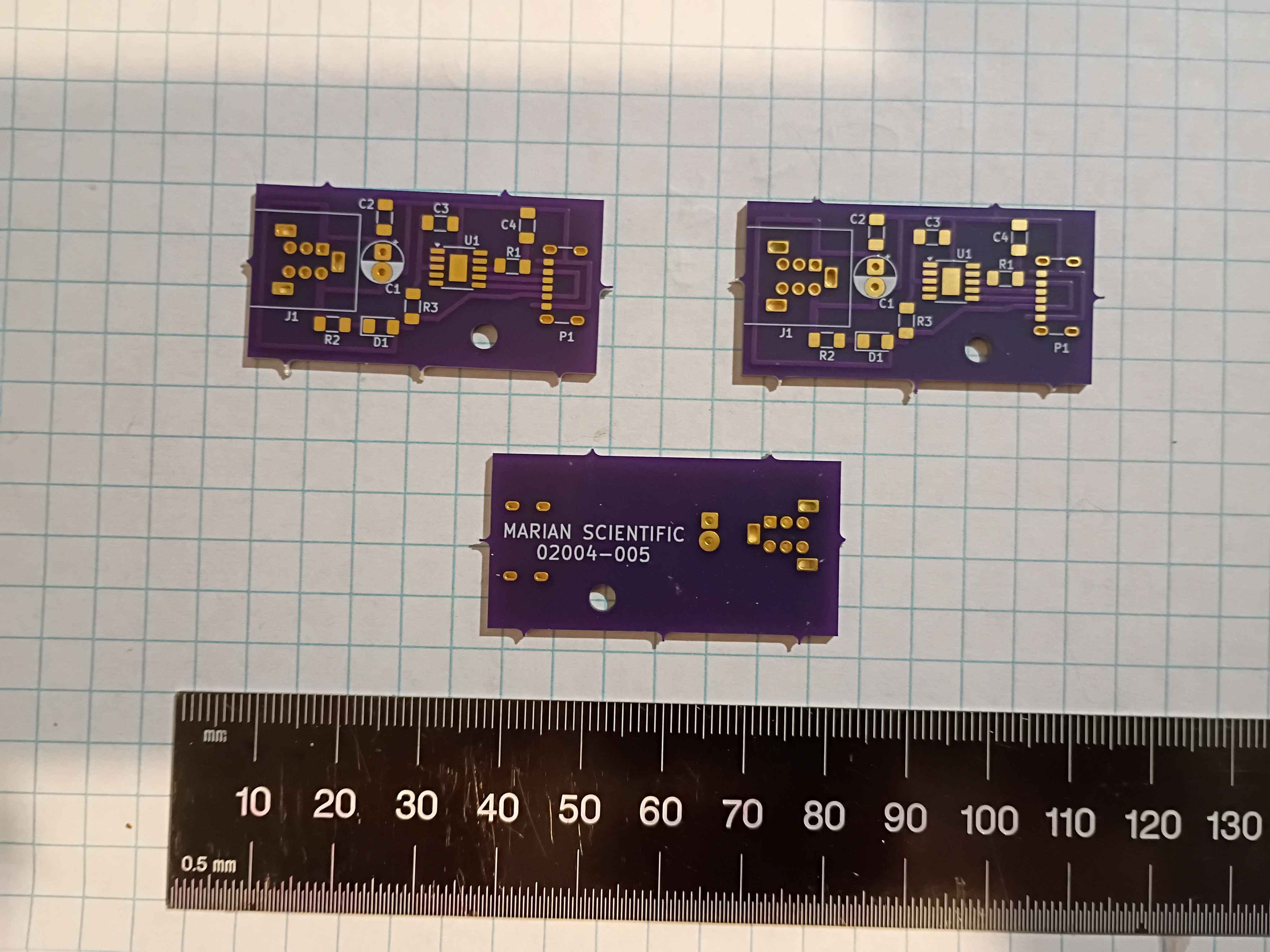
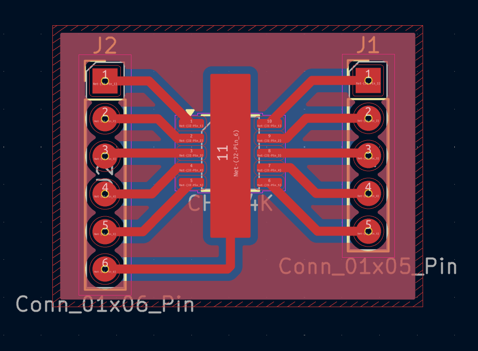
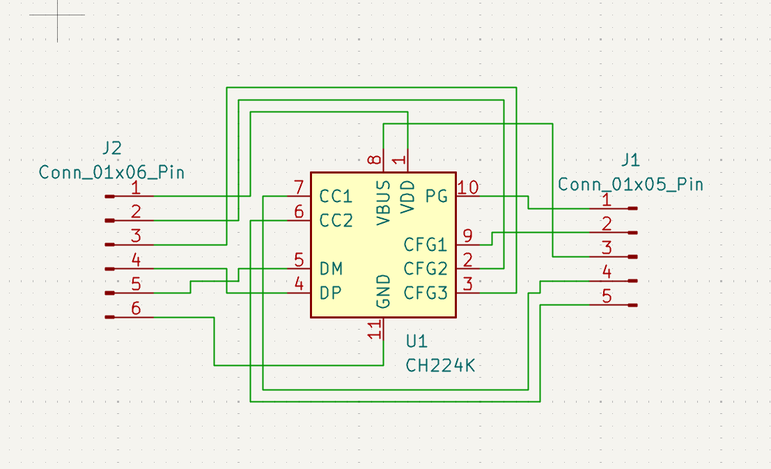
Designed breakout for ESSOP-10 IC. This is designated for testing purposes on a breadboard. 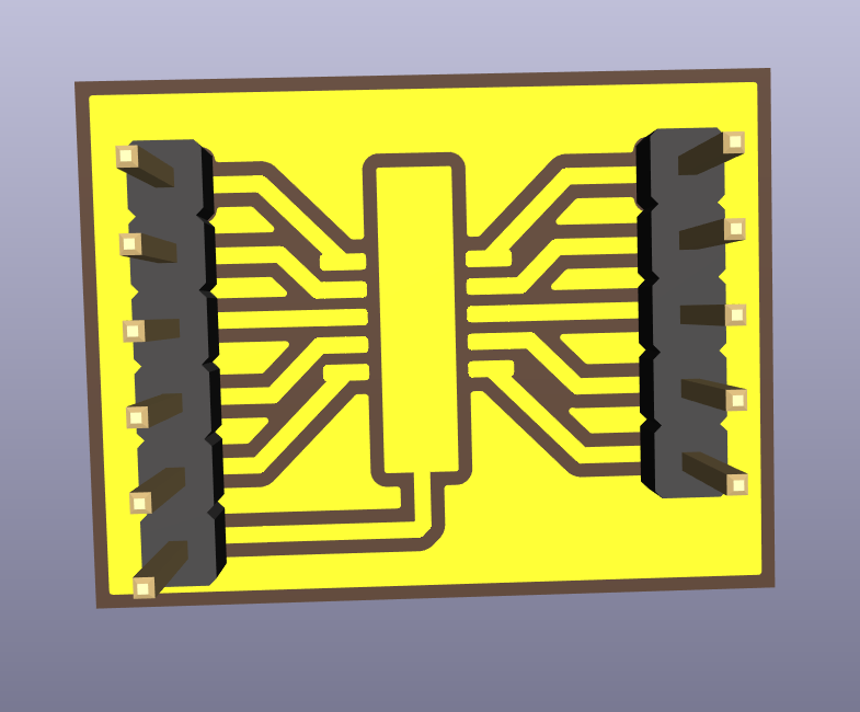
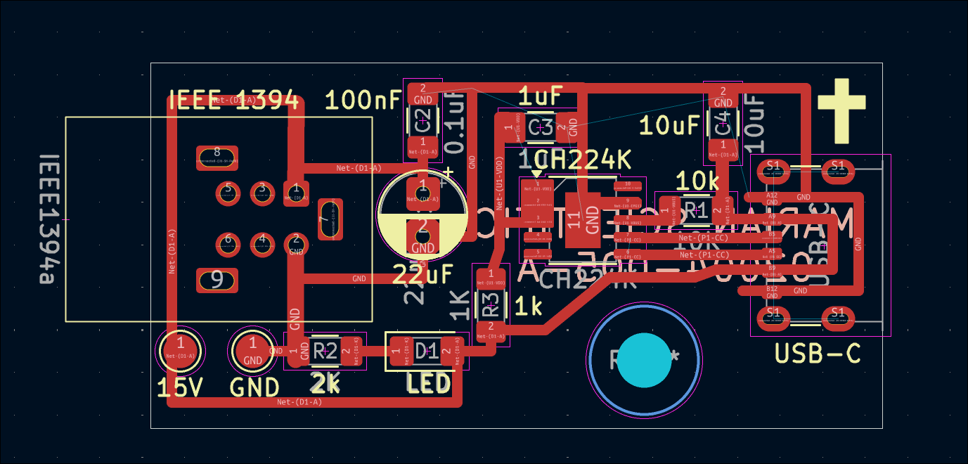
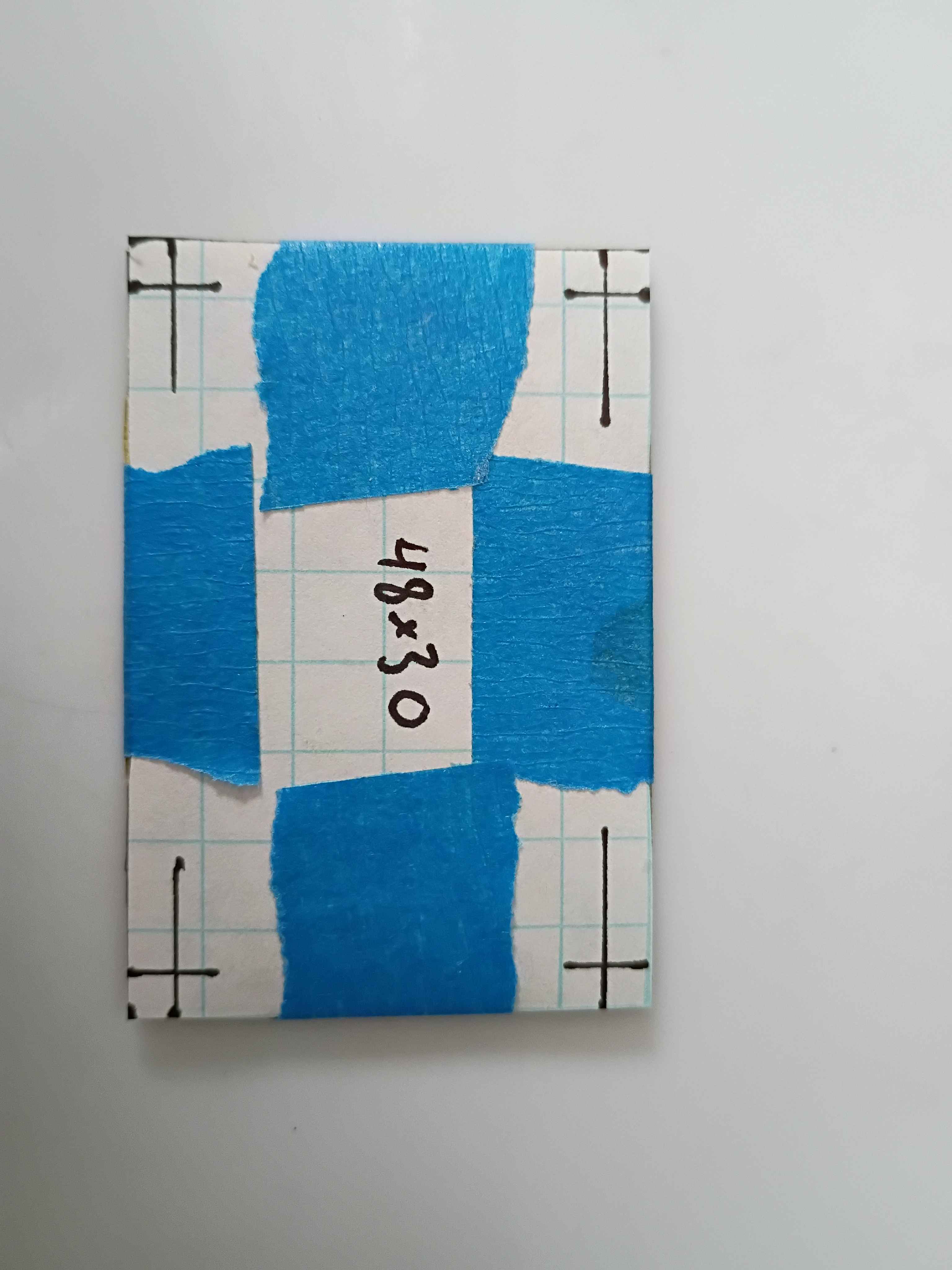
Shrunk the previously-validated 02004-004 PCB design by removing the hole pattern and adjusting the components slightly, creating the 02004-005 PCB shown below, which is 43x21.5mm. As a test of OSHPark's fulfillment speed, I ordered 3 of them (normally $7 for 3 with free shipping) with their Super Swift Service (half the processing time) and added $10 2-day Fedex shipping. It should also be noted that OSHPark lets you reupload and overwrite your designs (provided the new one is the same size) up until they are panelized. 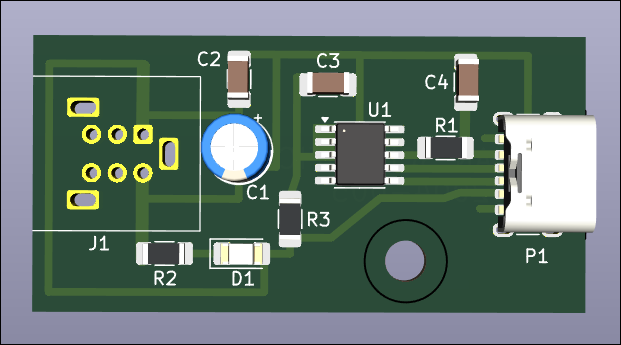
Etched the newer smaller 02004-004 trigger board. Designed and printed the 02004-004T1 drill guide to locate the mounting holes, and it worked absolutely perfectly. Popped the holes in and soldered the components. Put a few calculated drops of super glue to secure the connectors and successfully tested the circuit. Blue LED this time so I can save some green ones. Overall the fabrication went extremely well. 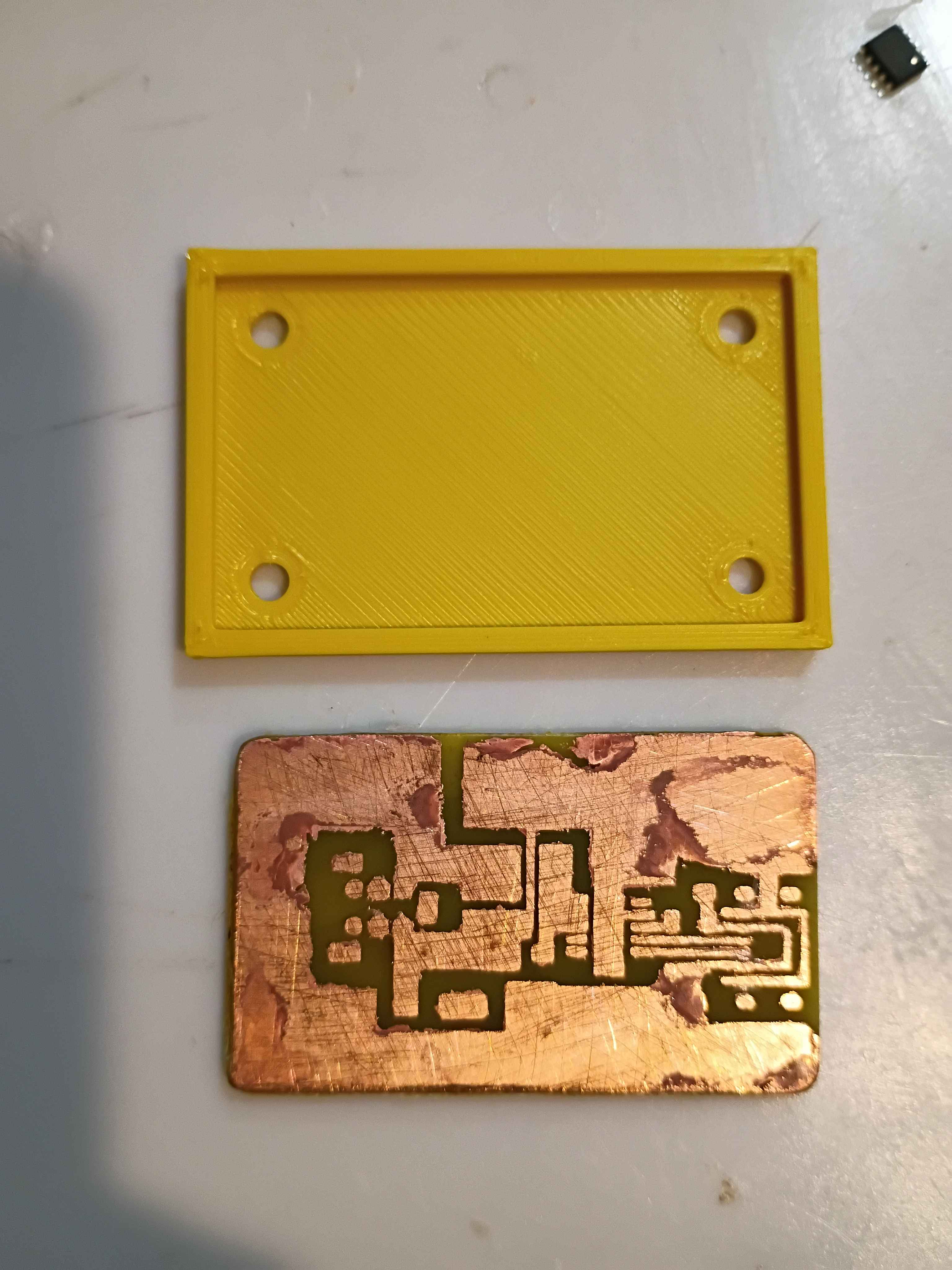
Repaired 1 of 2 additional evaluation units for the client and prepared them for shipment tomorrow. The other unit suffered too great of damage for repair, despite my best efforts. Developed a smaller and improved PCB design (02004-004) that removes the configuration resistor and jumper as well as increases the edge distance around the holes. This design is 8x7mm shorter and has several features for improved manufacturability. 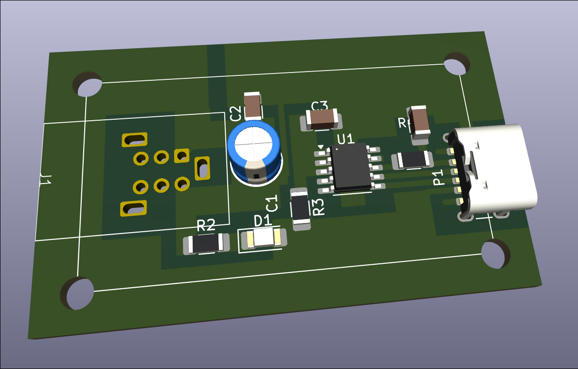
Notionally completed 2 more evaluation units, but determined after some testing that the USB-C connections are not adequate and need to be redone. Input provided to designer for future units but the current fabrication effort will require a clever approach. 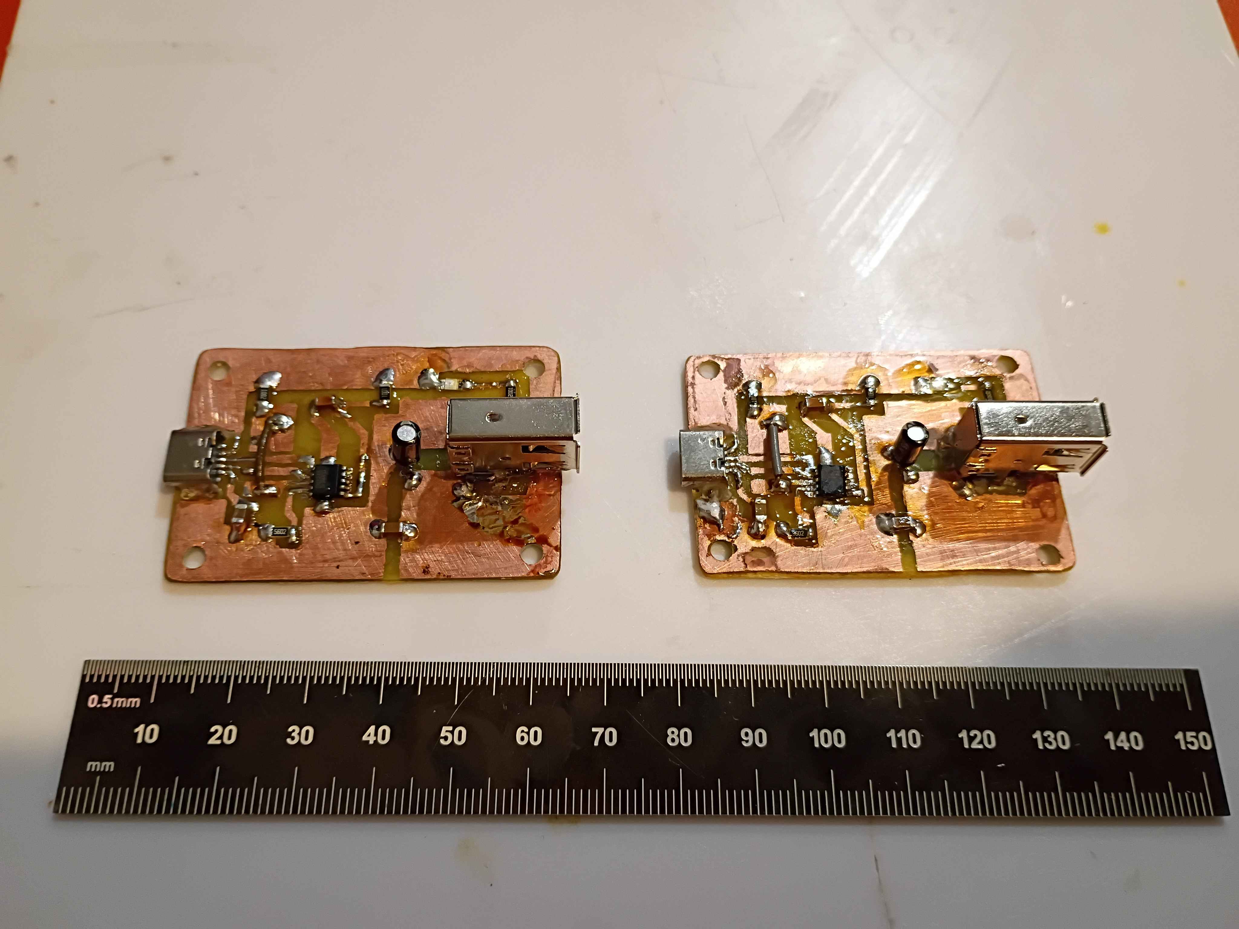
Began fabrication of 2 additional evaluation units for the client. Boards etched and drilled, and box assembly components printed, though one part requires reprinting due to some damage incurred during a prior attempted repair with a heat gun. 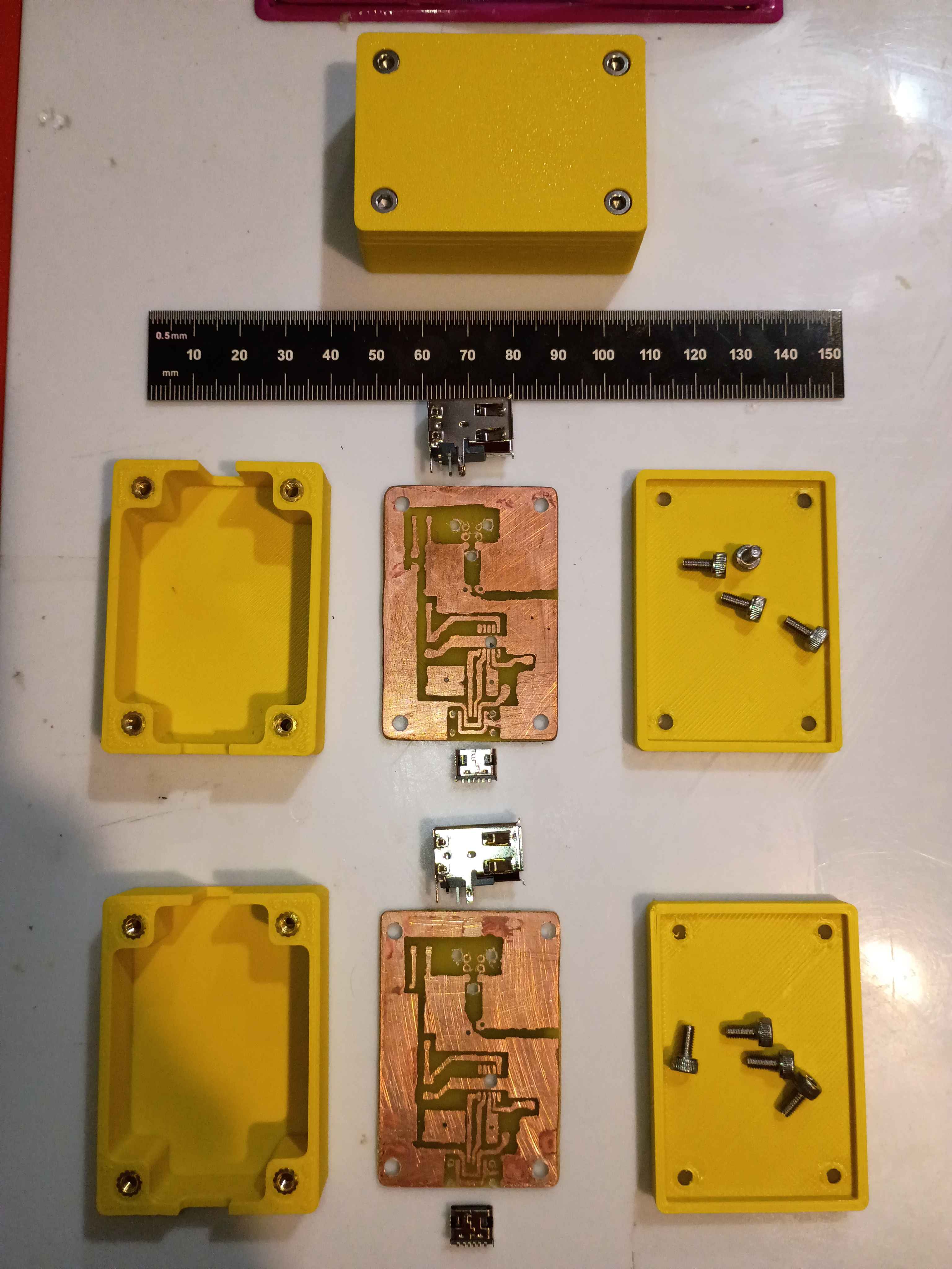
Today I updated the 02004-001 PCB.
Last week I made a parts List that's necessary for the manufacture of the 02004.
The circuit does seem to work with a 65W USB-C-PD charger, outputting the correct 15V. However, after repeated use, the USB-C port came a bit loose on the circuit and eventually detached. I resoldered it and applied even more super glue to secure it in place. I began reprinting the second case, this time letting the plate cool completely before popping off the print, in an attempt to remove the white haze from the bottom surface. 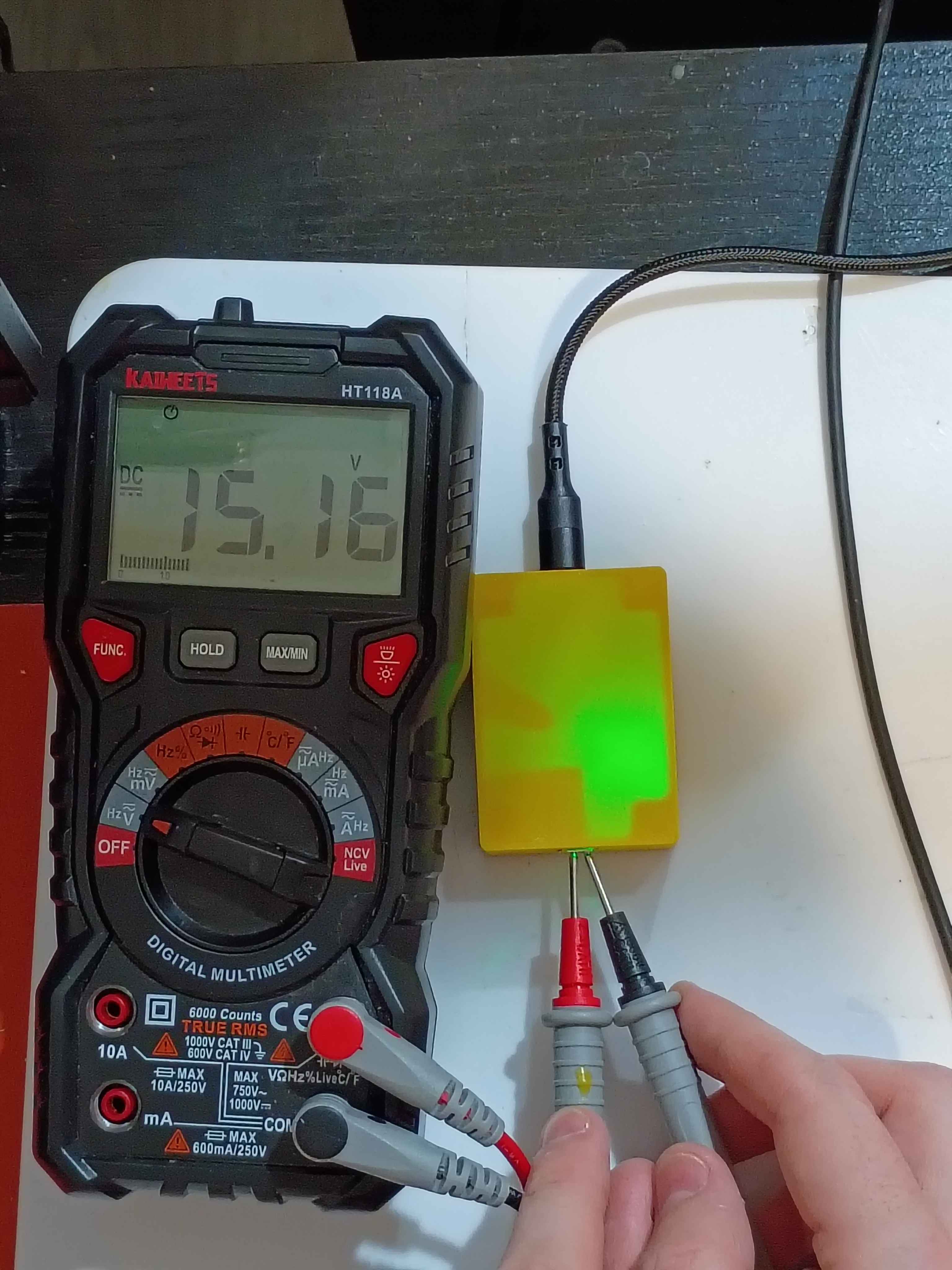
Printed revised box assembly out of ASA and assembled everything together. Had to tune the new printer for this filament for the first time. 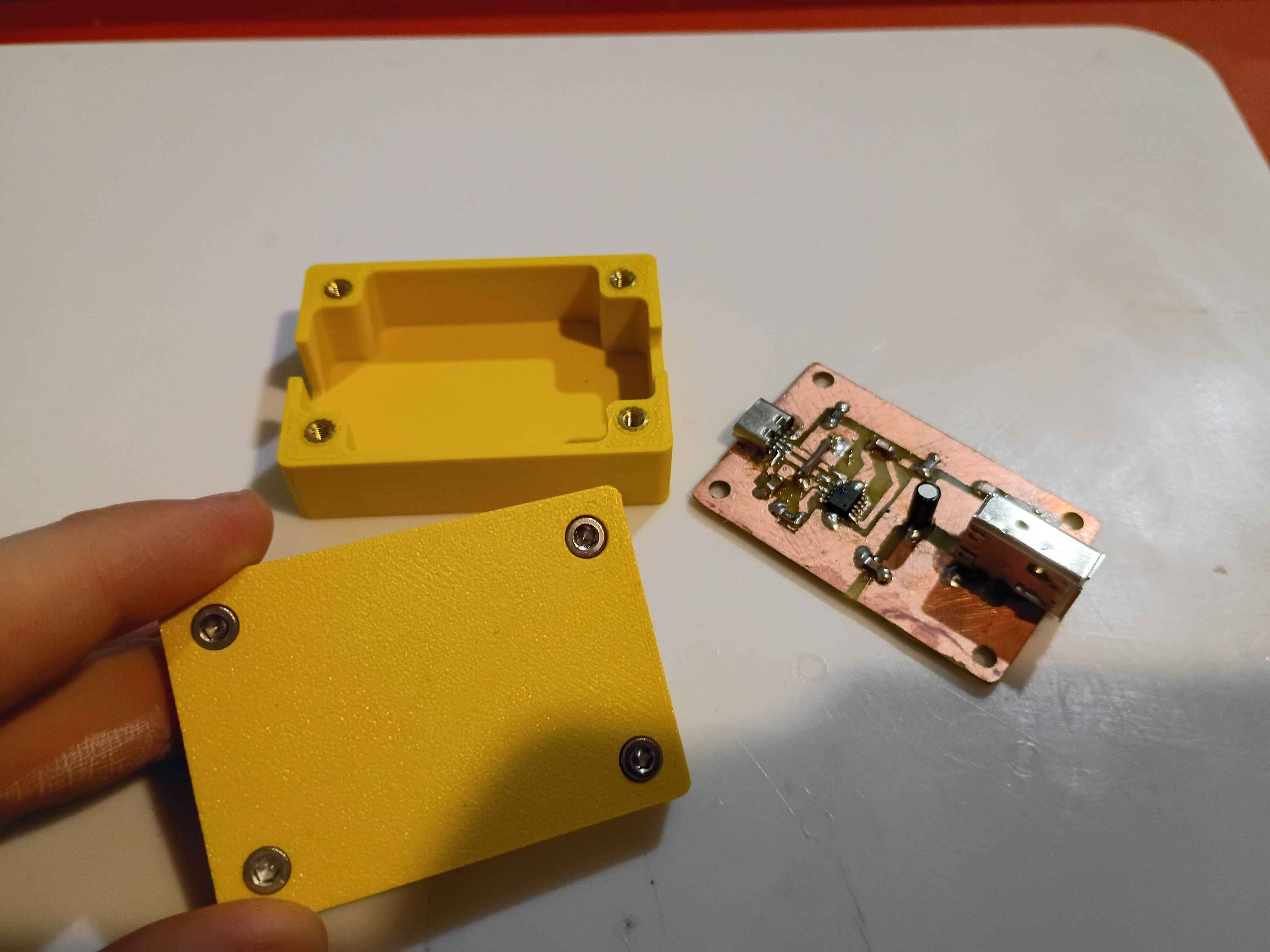
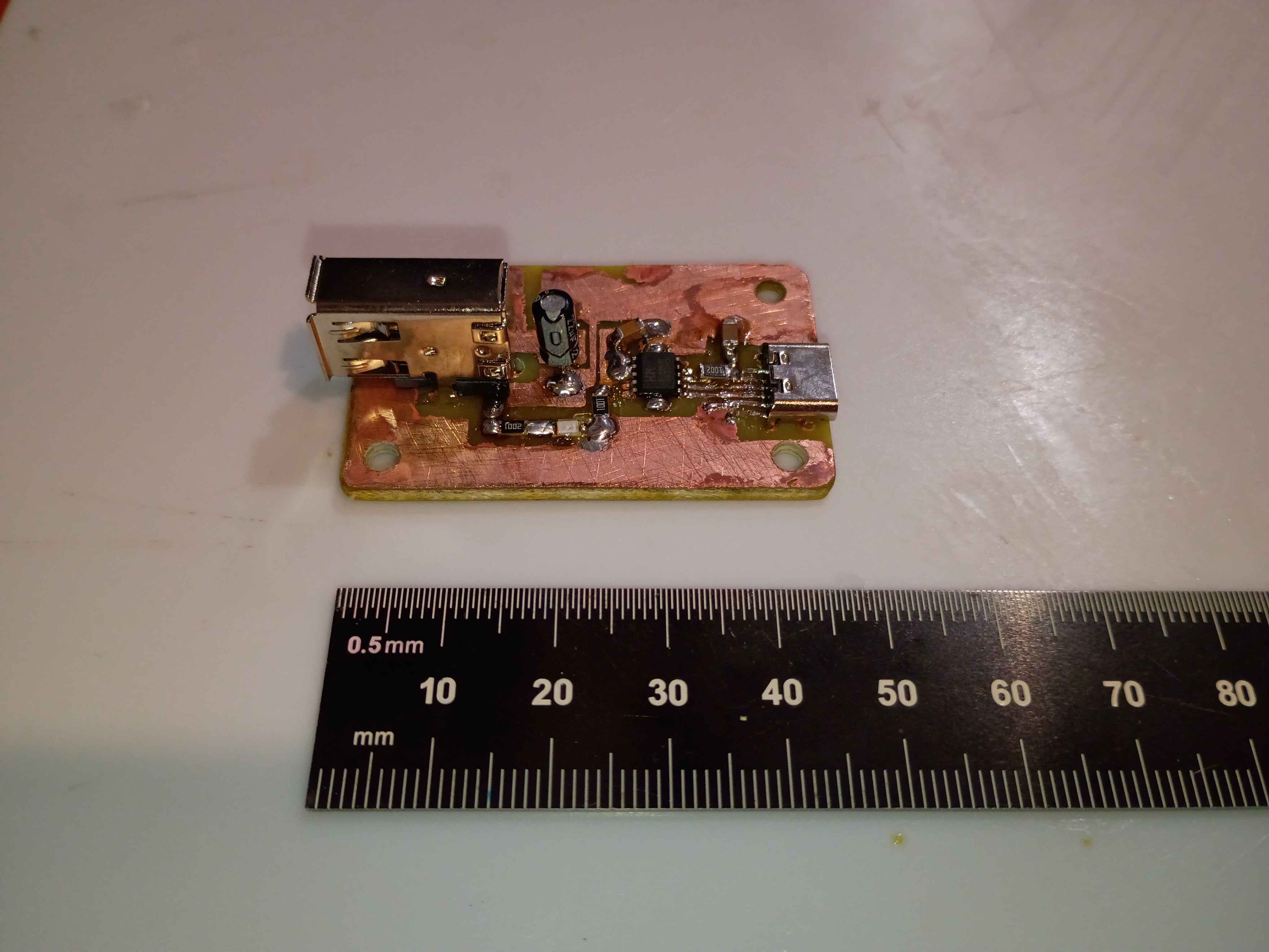
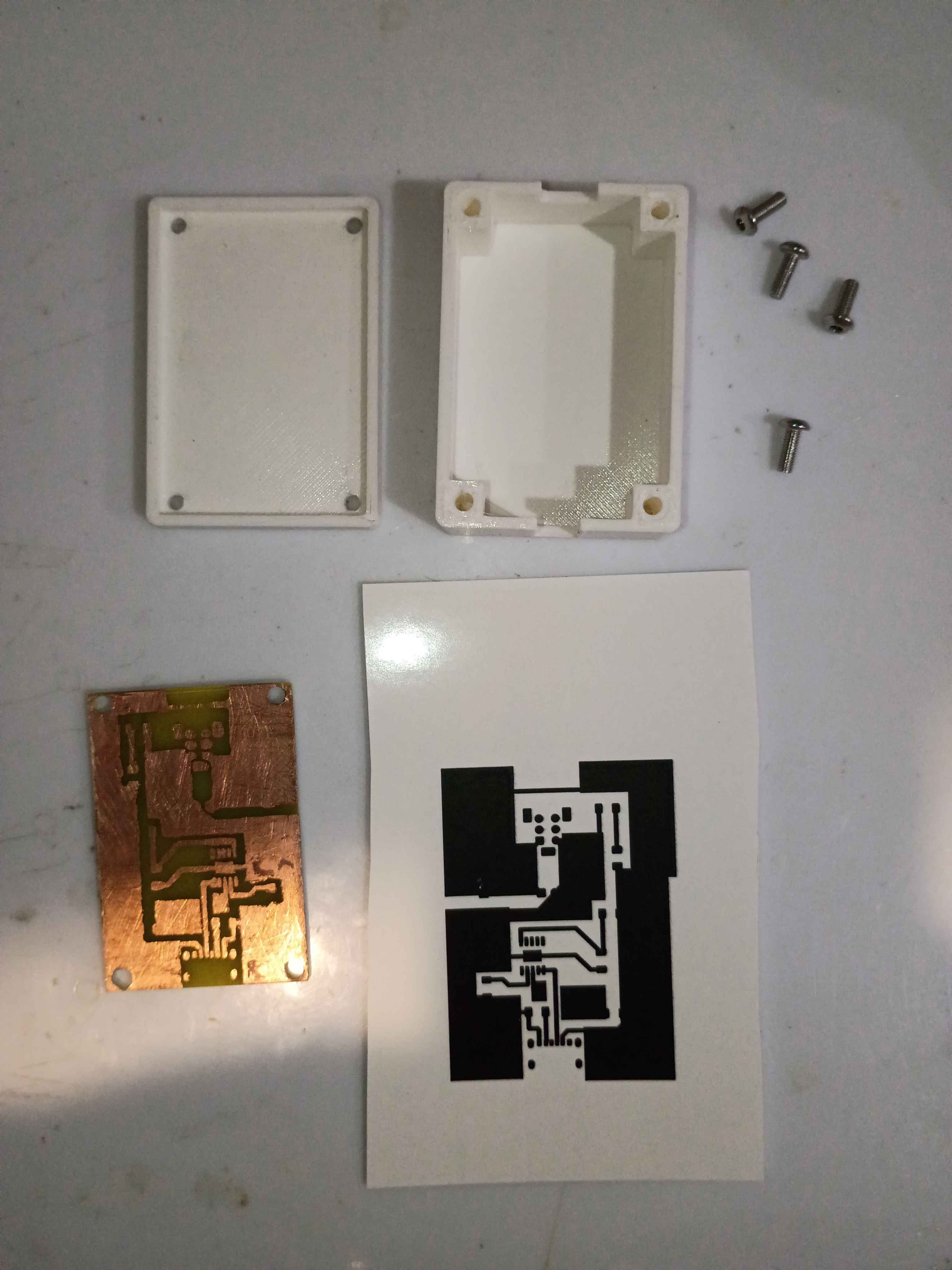
Completed second iteration of the prototype circuit board. It took 2.5 hours from printing the mask to testing the device. For future reference, I did immediately quench the board after toner transfer, so that didn't seem to make a difference. Still only get 12V max output, hopefully tomorrow I will receive a PD charger and cable capable of 15V. 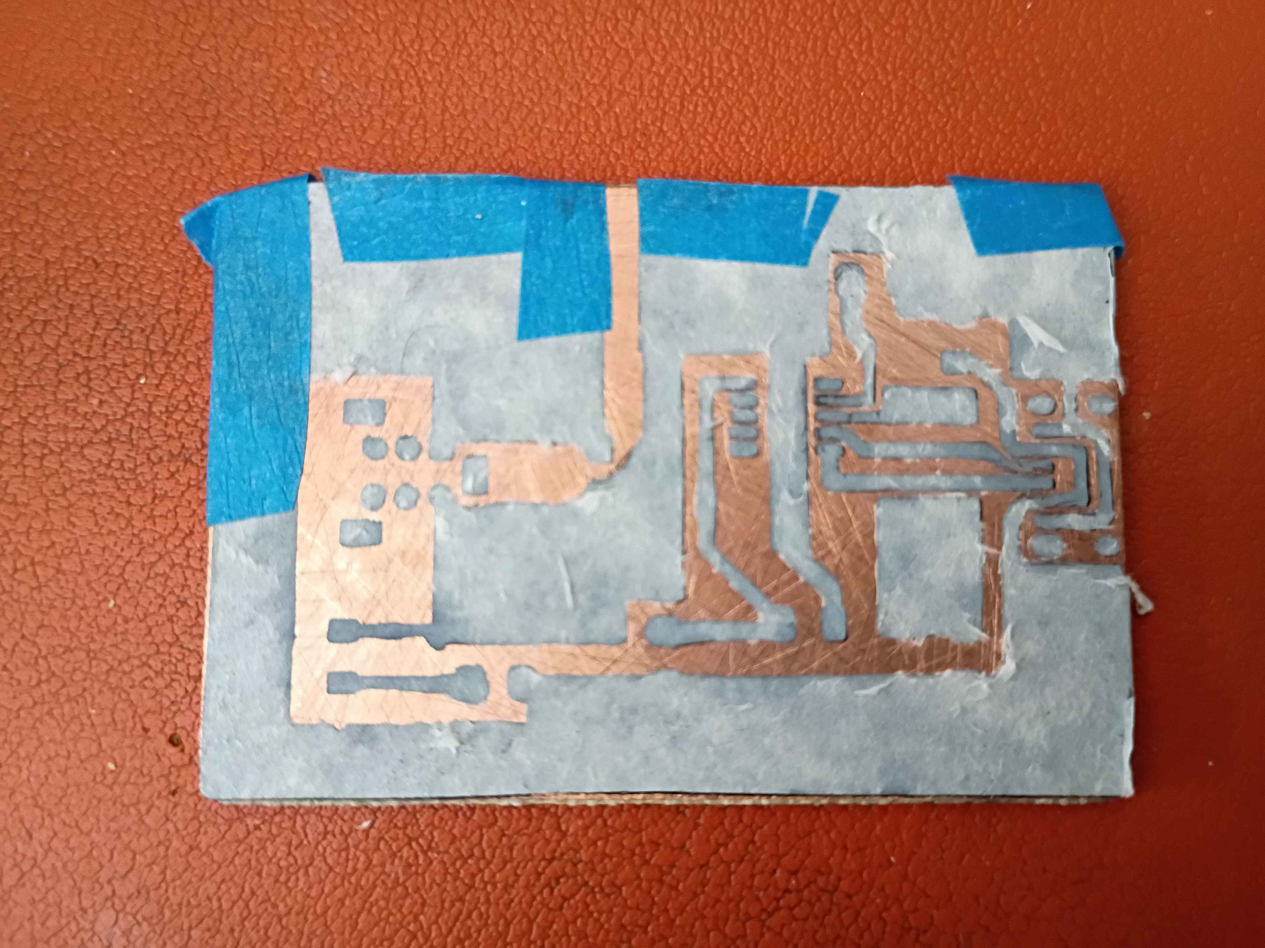
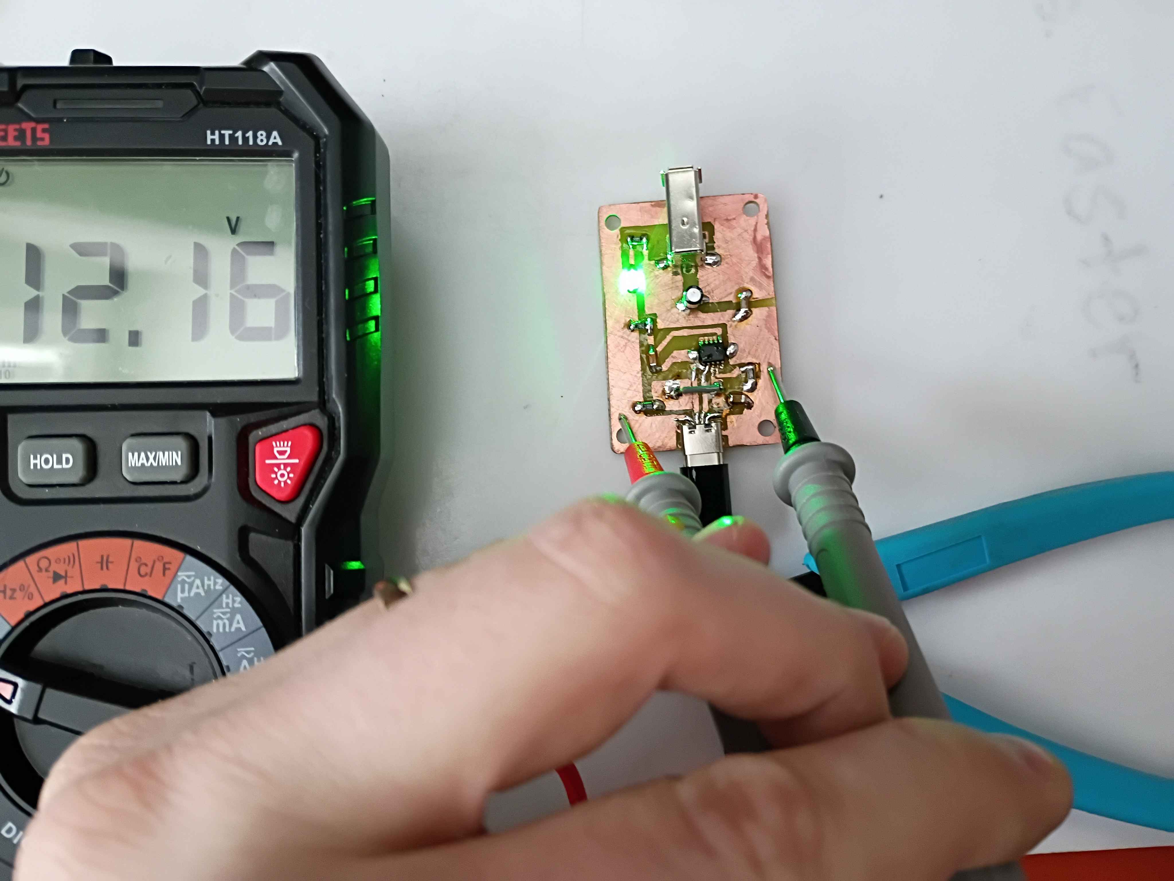
Received FireWire sockets and trigger IC and tried several iterations to get everything working. Eventually the circuit essentially works, though for whatever reason I was only able to negotiate 5, 9, and 12V. 15 and 20V did not work. I am sourcing different cables and chargers to see if that might have been the problem. Consulted on PCB design revisions for manufacturing considerations. 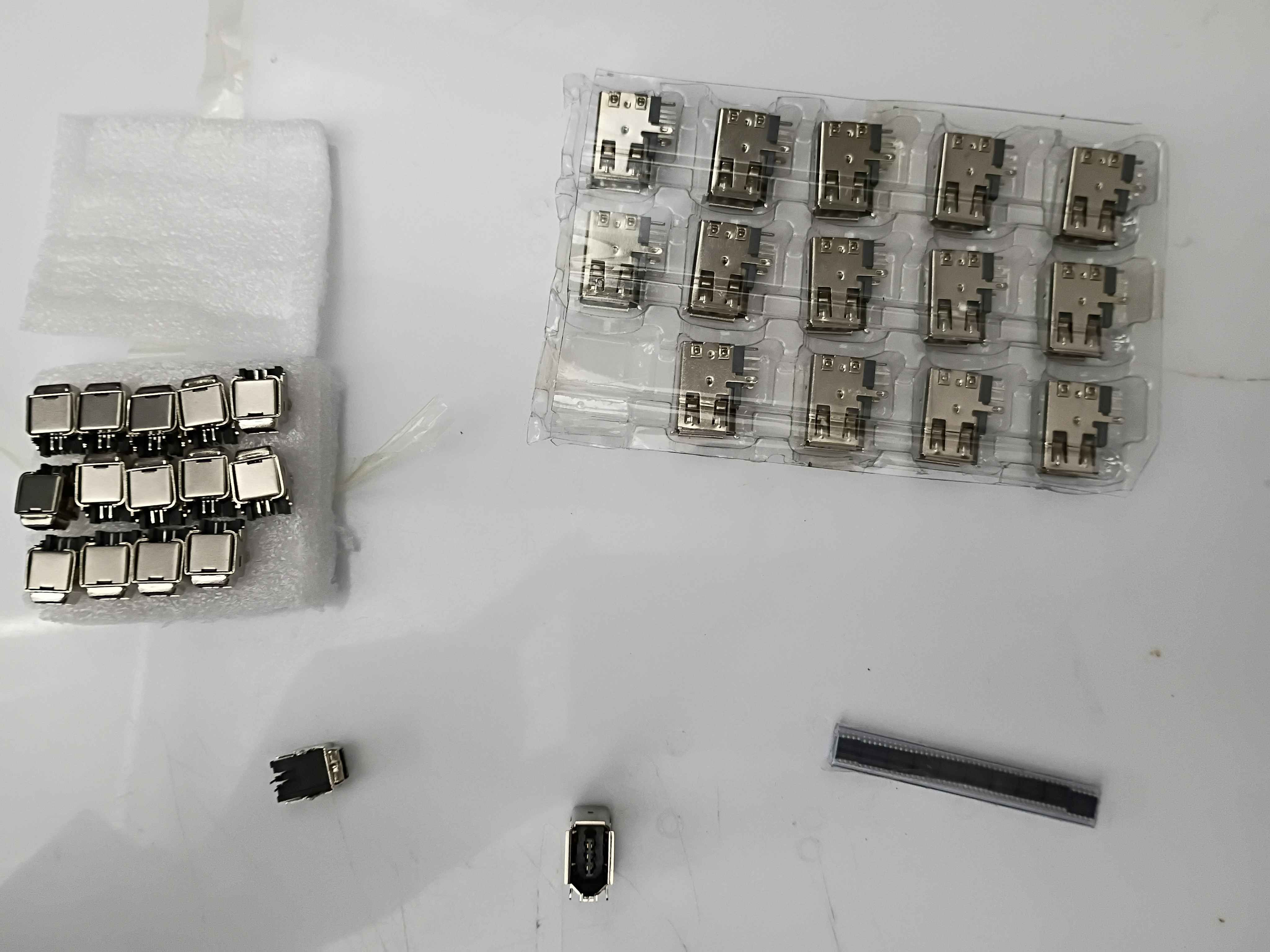
Received capacitors in mail. Drilled holes in circuit board and soldered caps and LED. Confirmed the LED is mounted correctly. Now we are just waiting for the IC and FireWire socket to be delivered. 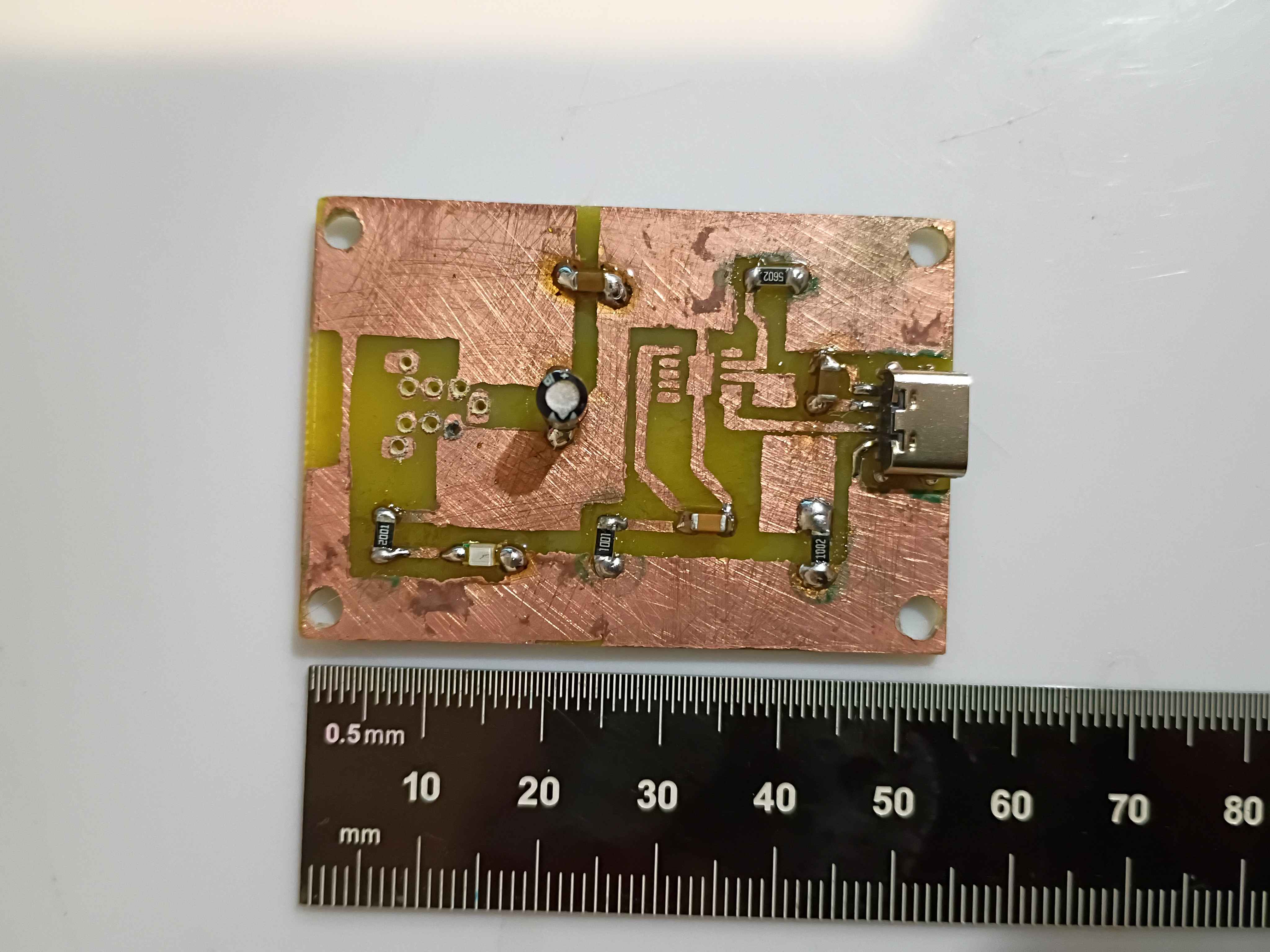
Reviewed the box assembly and PCB designs for manufacturing considerations and provided feedback to the designers. Incorporated the manufacturing feedback into the box assembly. Soldered SMD resistors and USB-C connector (required 1.0 mm holes drilled) to the test board. Purchased ASA filament for the eventual final box print and the necessary capacitors for the circuit. 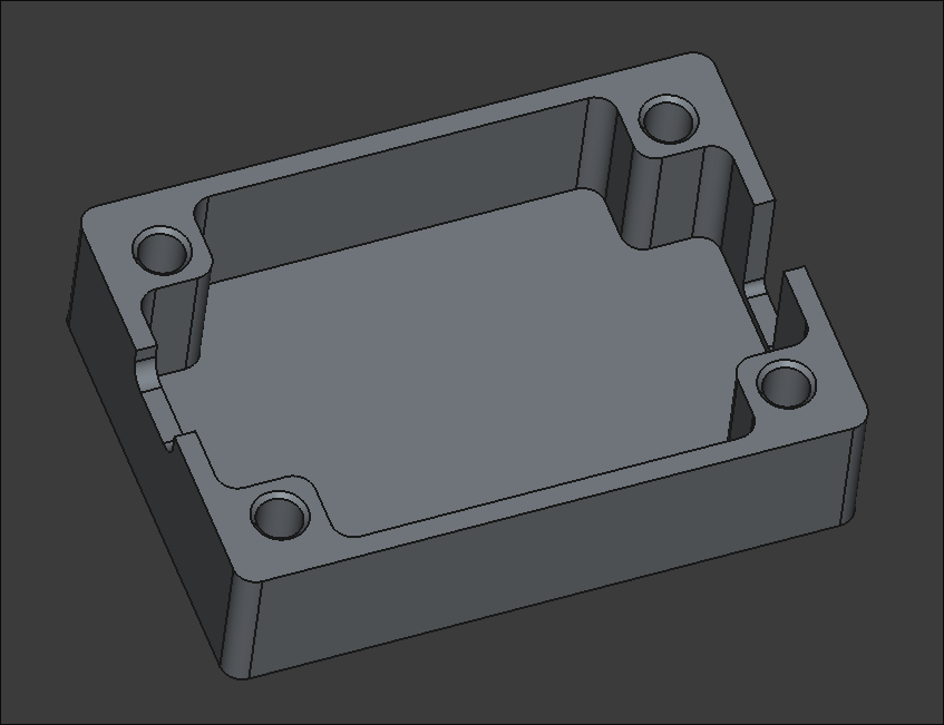
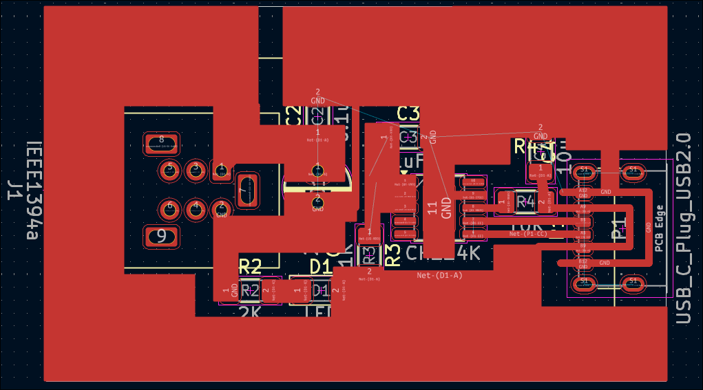
Yesterday, a PCB of the Firewire PD was designed. This design is designated for prototyping and isn't considered final. Surface mount components will be used for this project and thus the copper for this will be on the top (front) as opposed to earlier designs where the back was reserved for the copper. There is one rear copper connecter that will be implemented via a jumper.
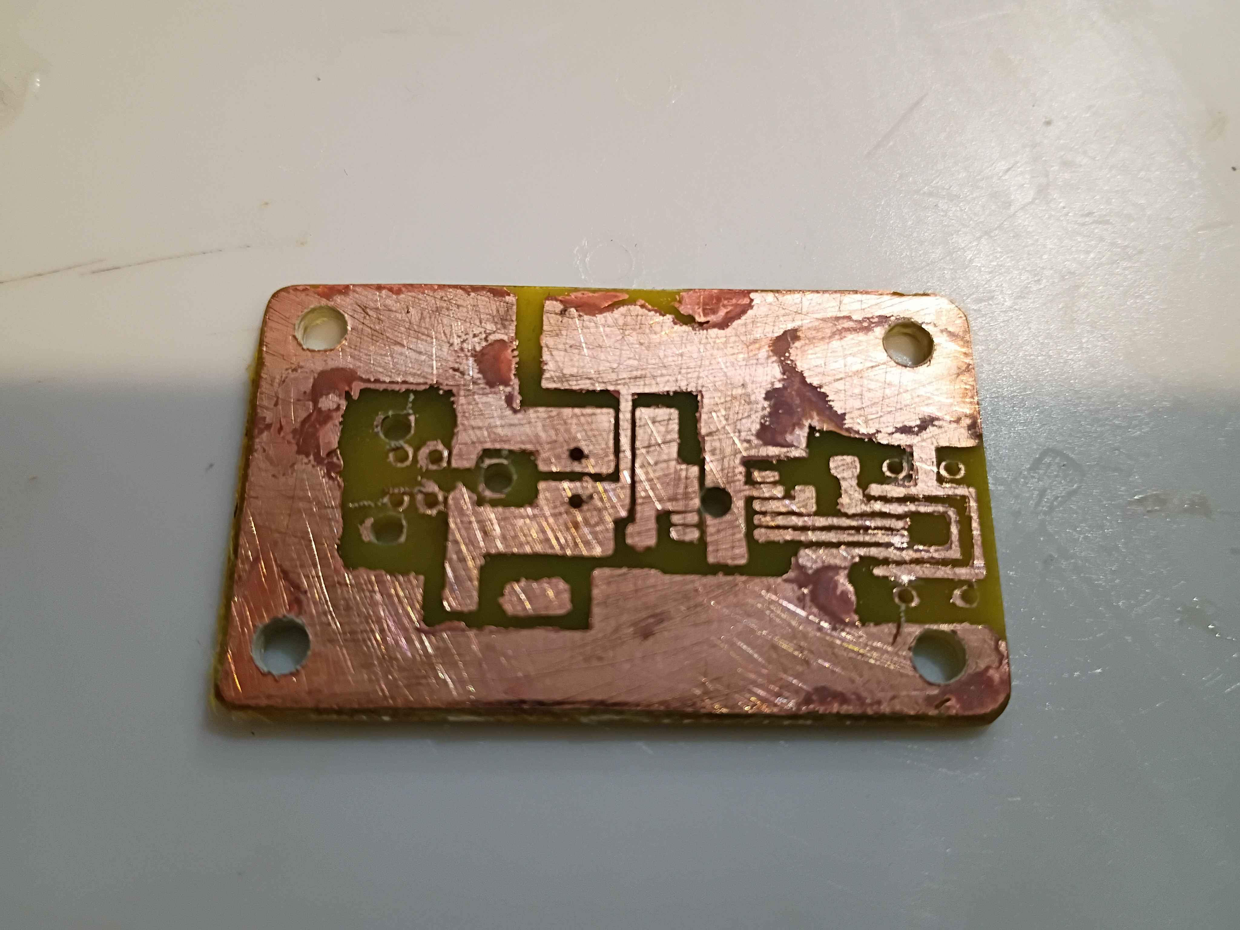
Fabricated the preliminary base PCB, while demonstrating to Anthony. Holes were drilled for assembly. On the next iteration, the copper pours on the mask should be exactly sized to the edge cuts, the hole patterns should be brought onwards roughly 1mm in every direction, if possible, and the box assembly should allow for an extra 0.5mm of tolerance around the board edge. That being said, this assembly will serve as a testbed for the circuit when all components arrive. 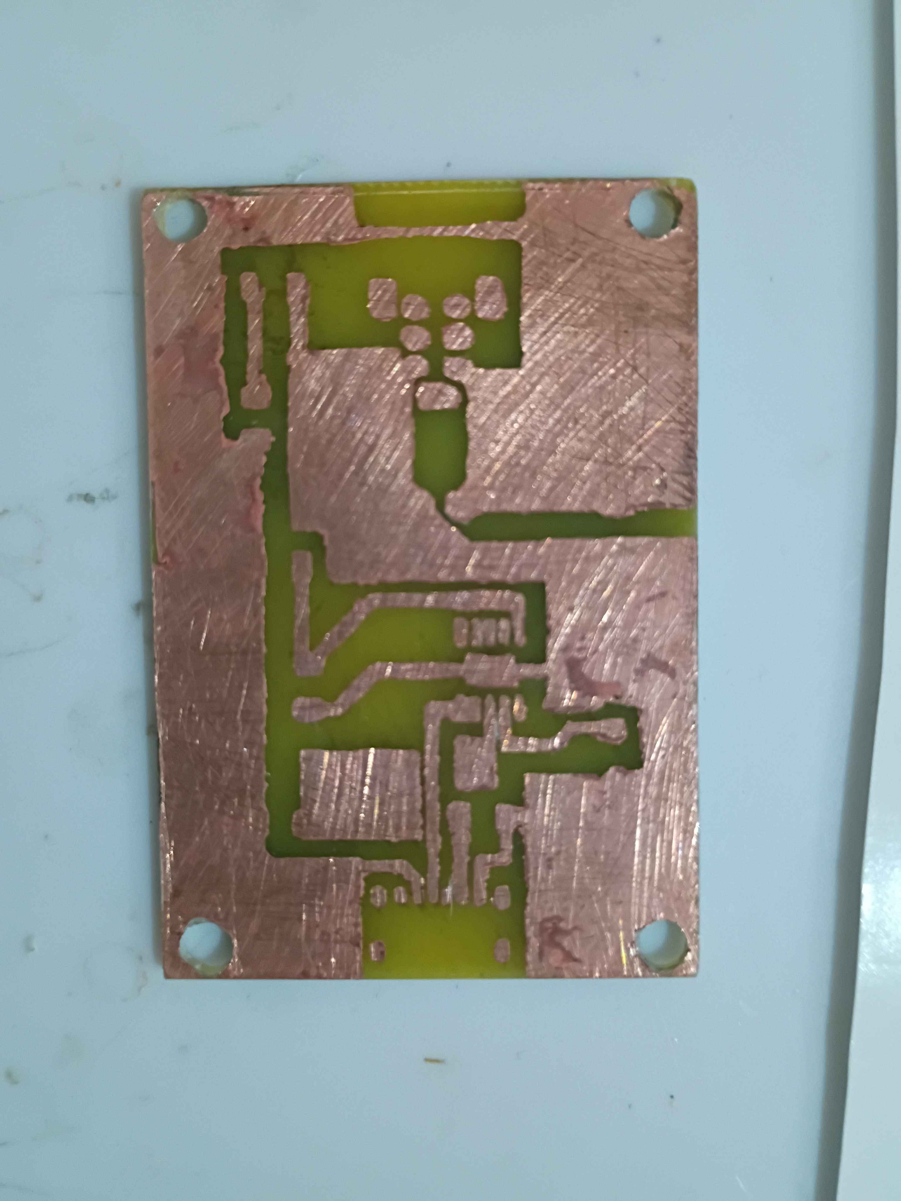
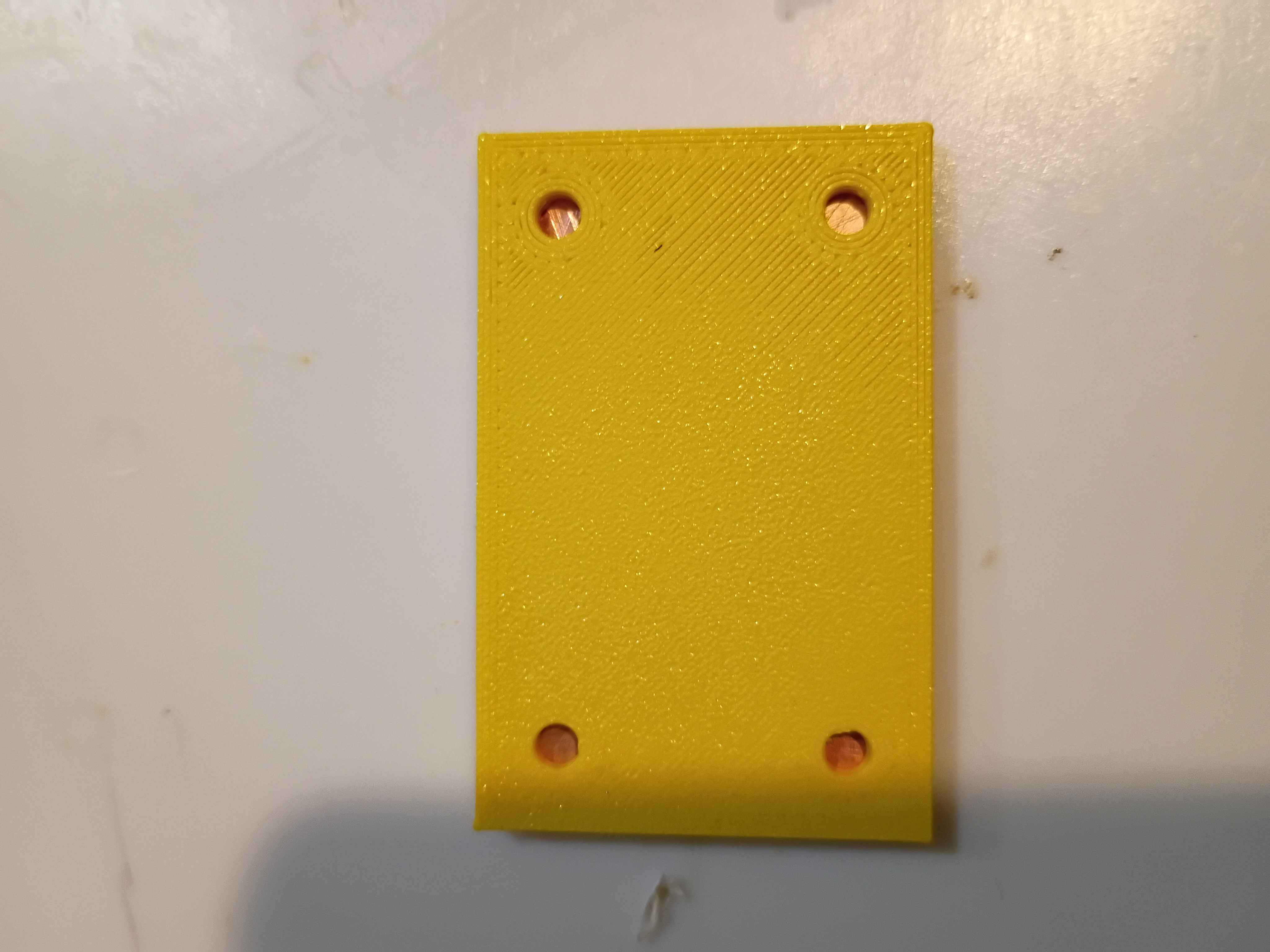
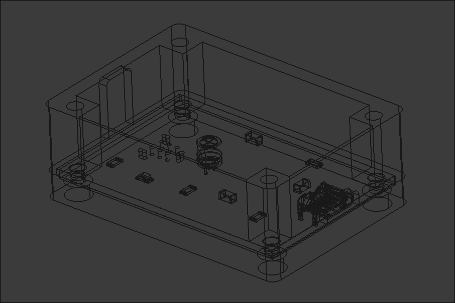
Consulted on the PCB layout and mocked up a draft two-piece box assembly with notional slots for the connectors. Sliced and launched a test print on the new facility Voron 0.2r1 printer using PLA. Assembly will take 4x 3x4x5 M3 heat-set inserts for M3 socket head screws that clamp everything together at once. 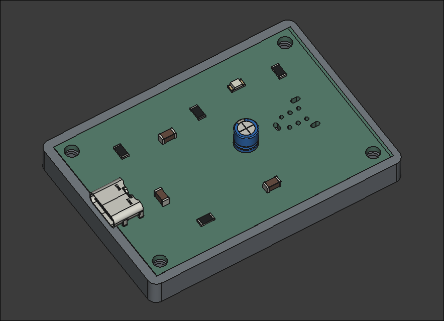
The DIP Firewire (Keystone makes a version called 930) was ordered and the 4 pin Firewire was ordered. The DIP Firewire ordered from here and the footprint was modeled from here (the 930 from Keystone Electronics). There wasn't a footprint model provided from the retailer, so one was taken elsewhere. The 4 pin Firewire ordered from here had a footprint provided and my custom footprint was modeled from that.
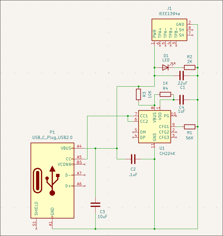
A couple of days ago, I was tasked to create a PCB that essentially converts power from a USB-C to a firewire socket. A rough schematic was made and a custom footprint was created for the anticipated firewire female port. Yesterday, the Schematic was updated from a reference workflow doesn't have a footprint for the IEEE1394 (firewire) female port. So a suitable part was researched for this project and one was found on mouser here and Digikey as well, here . This is the 929 by Keystone Electronics. This datasheet schematic was used to make a custom footprint for the 929. Here's the custom footprint.
Helped launch project by brainstorming solutions to client request, conducting research, purchasing necessary components, and assisting with preliminary draft circuit schematic and PCB layout.