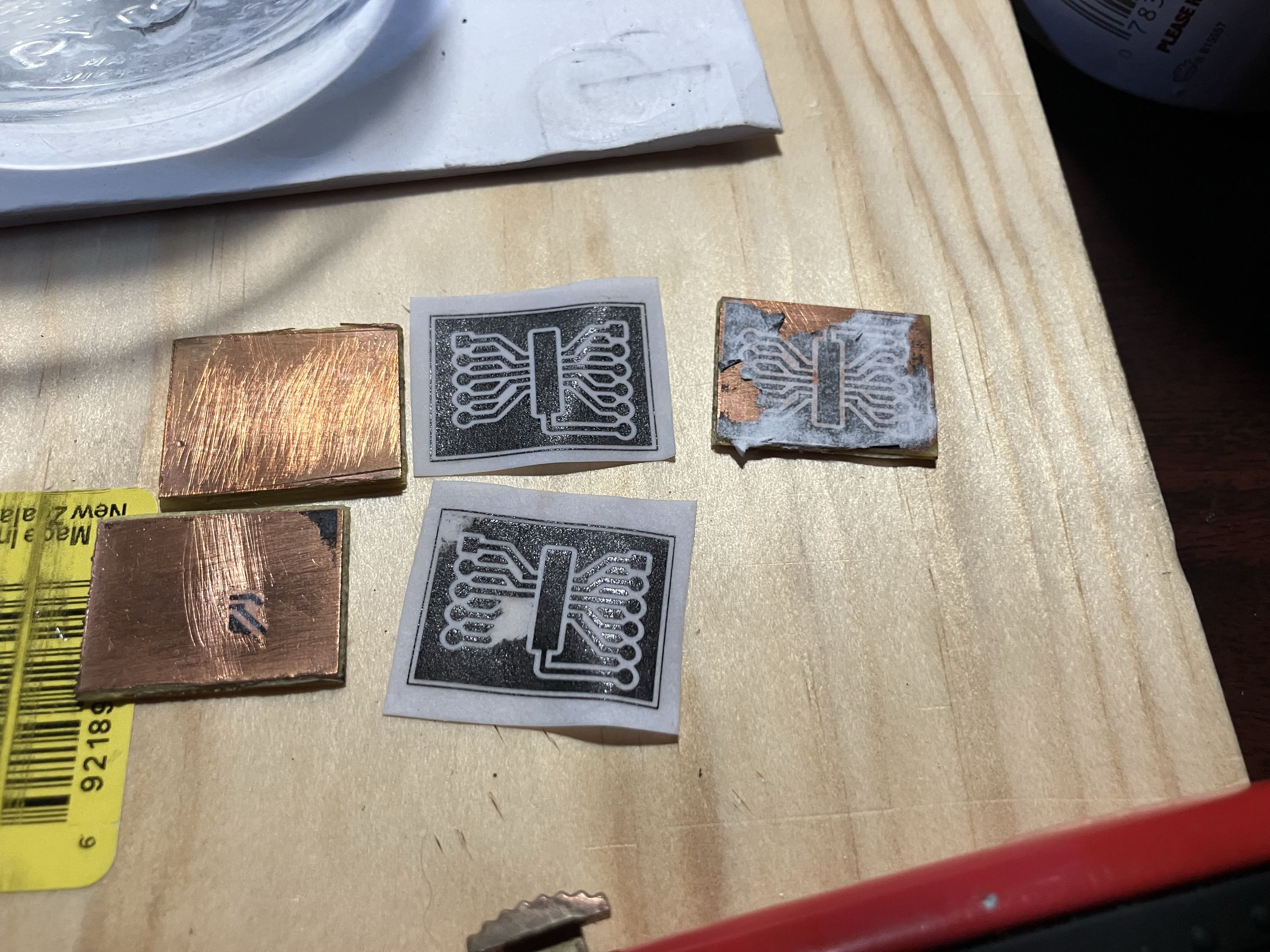
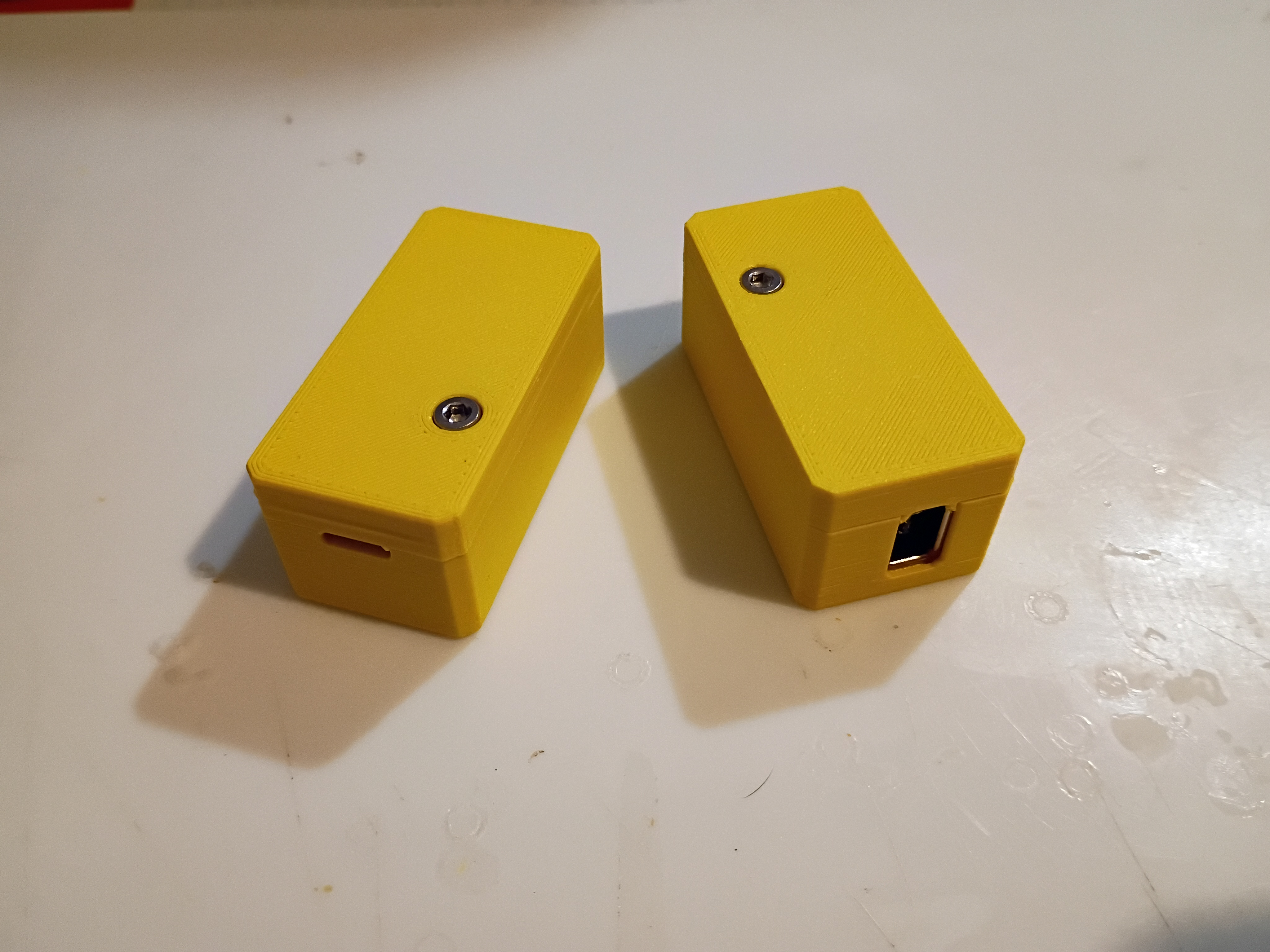
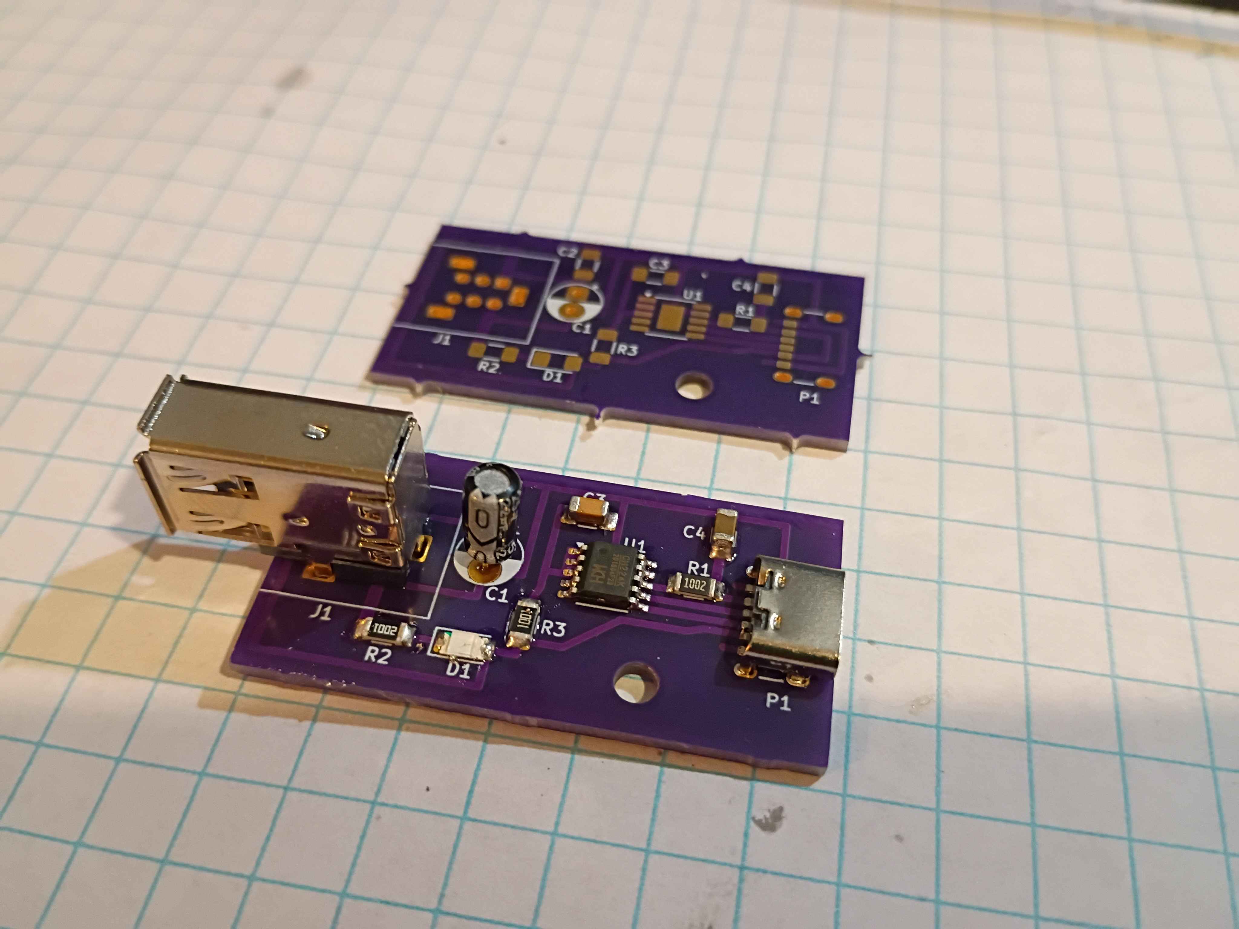
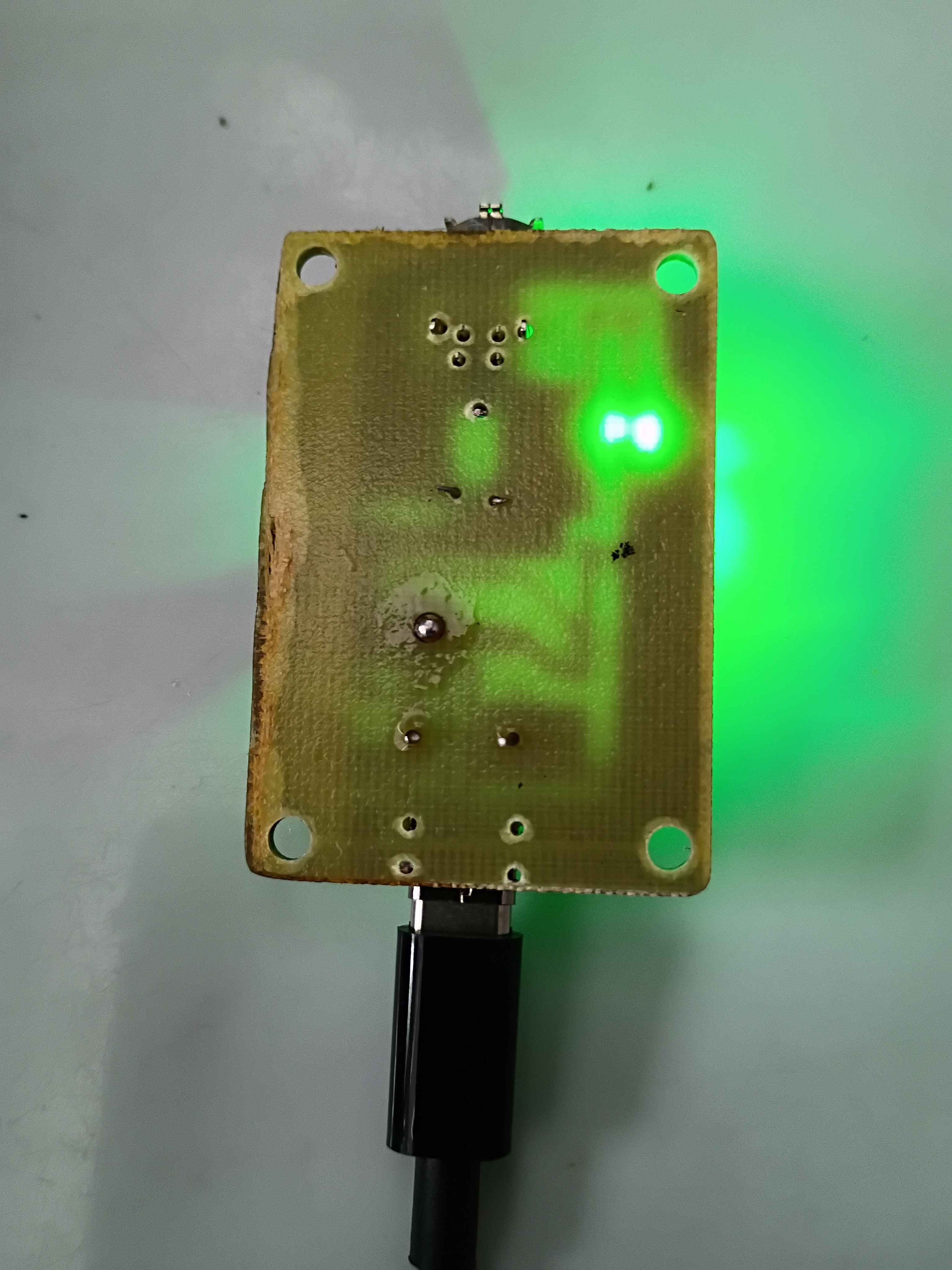
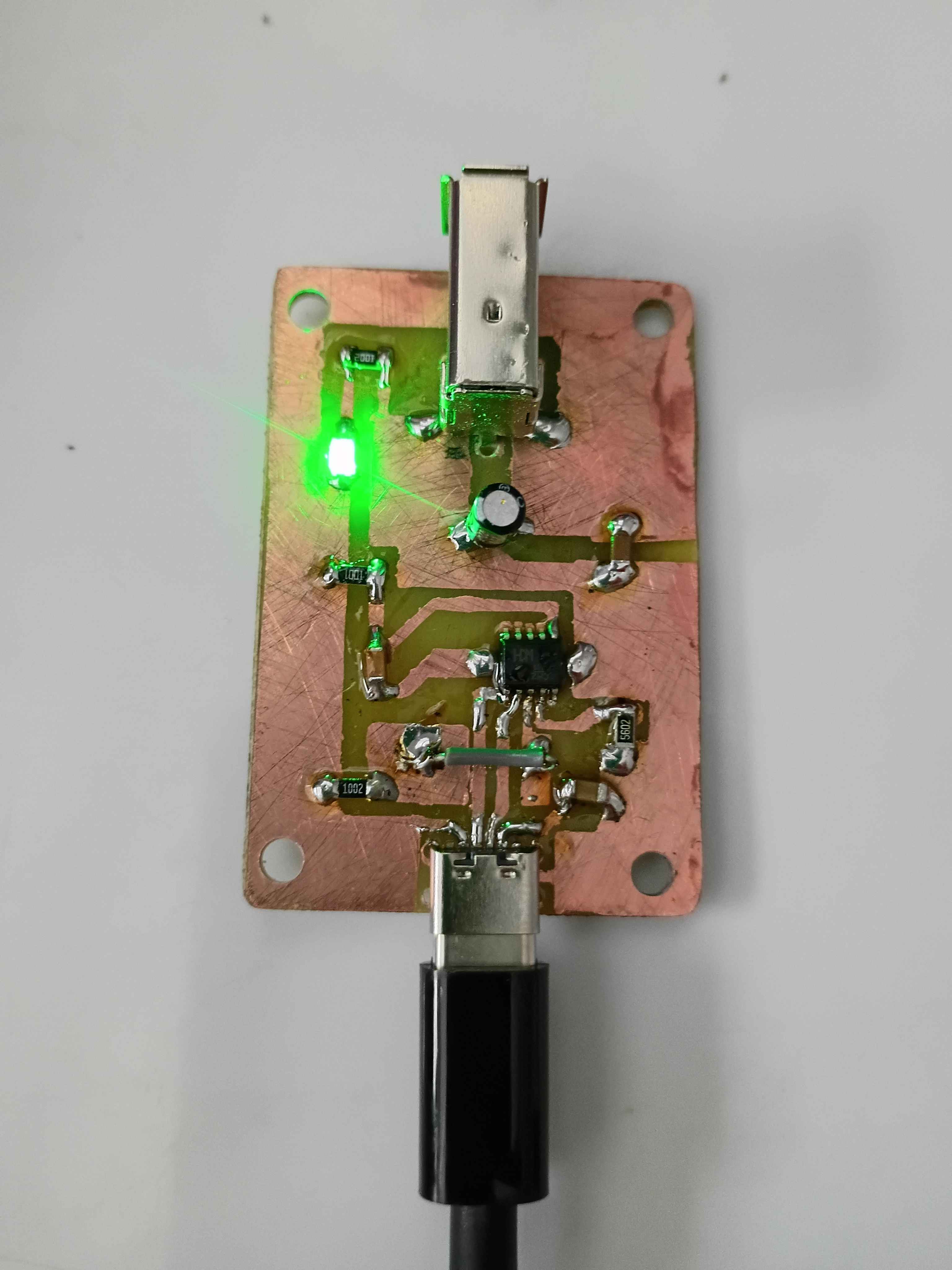
Made progress on the ch224k breakout pcb. 1 was successful and 2 failed. I believe the first succeeded because it was allowed to cool off before submerged in water.
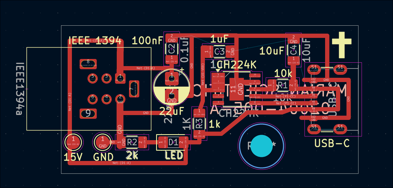
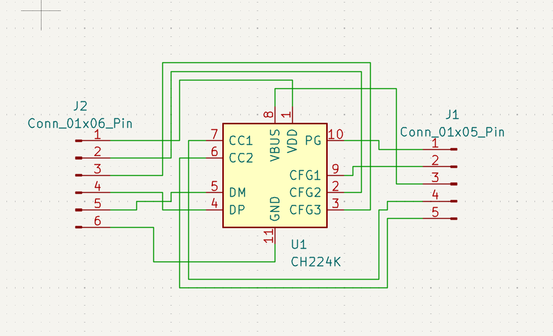
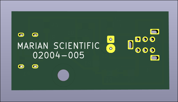
Revised PCB (02004-005-A) with some final lessons learned including test pads, extra exposed copper on the USB-C for solder mounting structure & component labels. 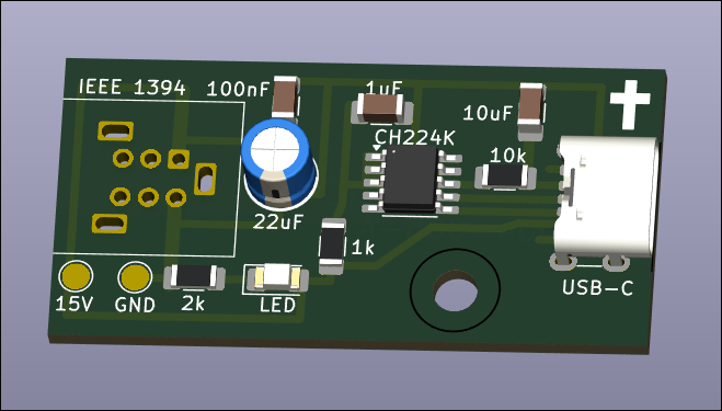
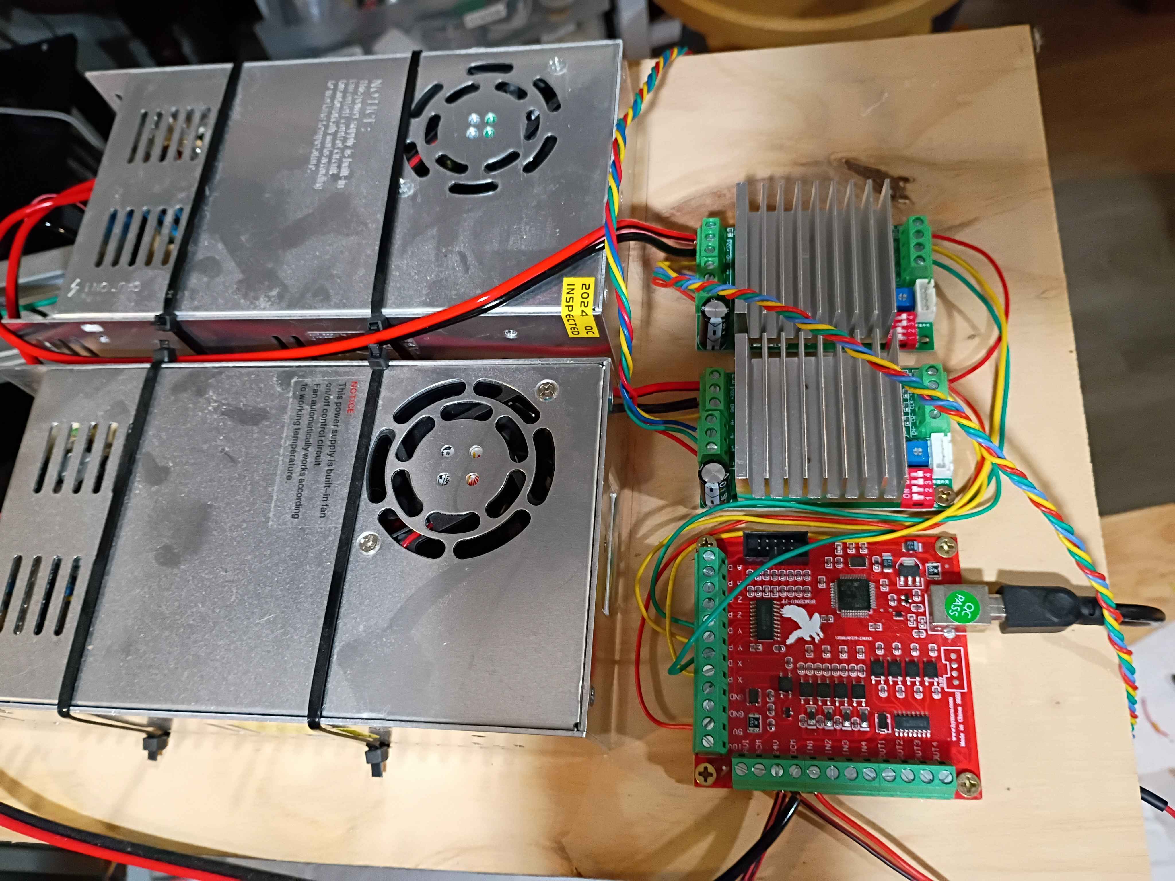
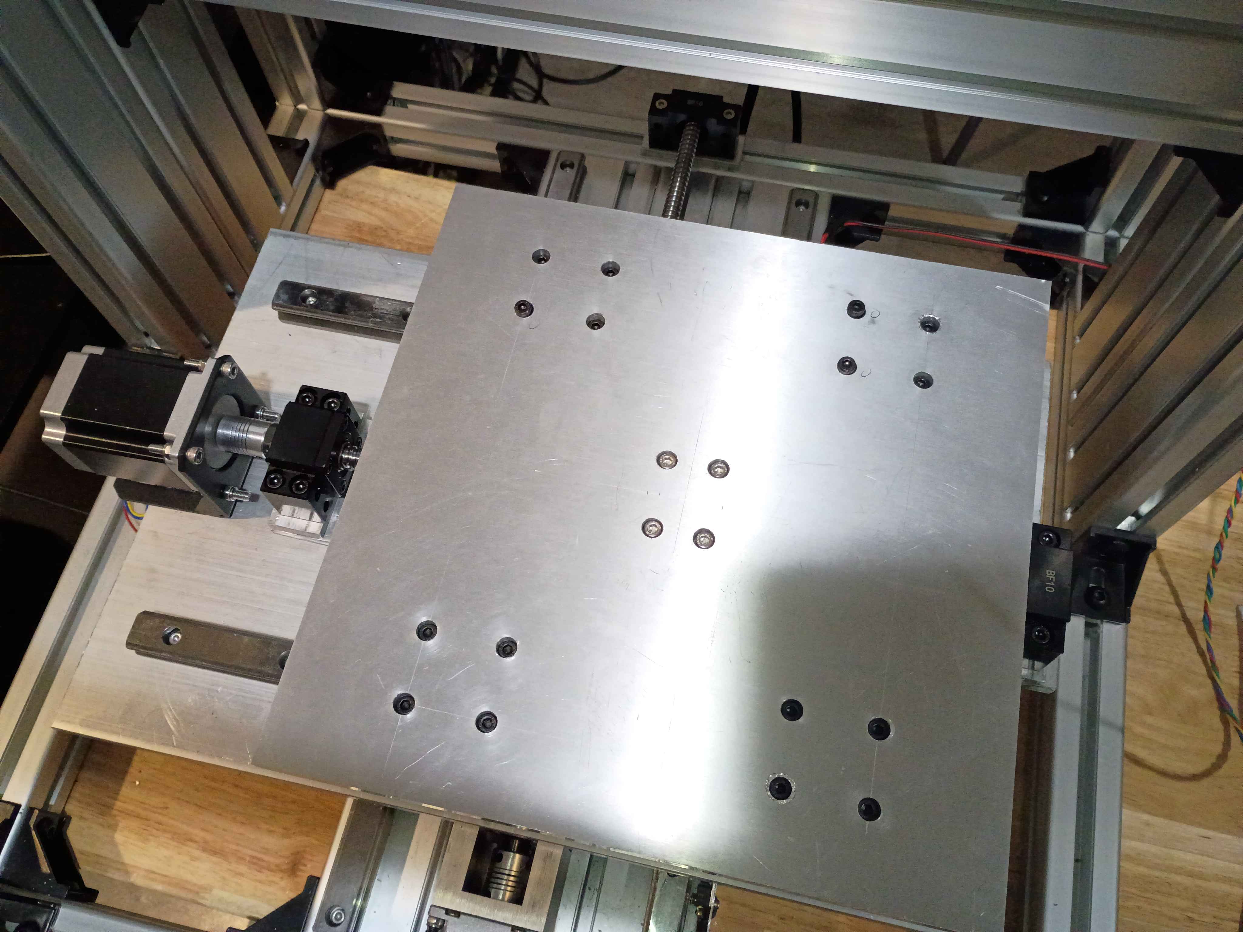
Redrilled and assembled Y motion to eliminate binding. Added Y motion electronics and tested the control software. 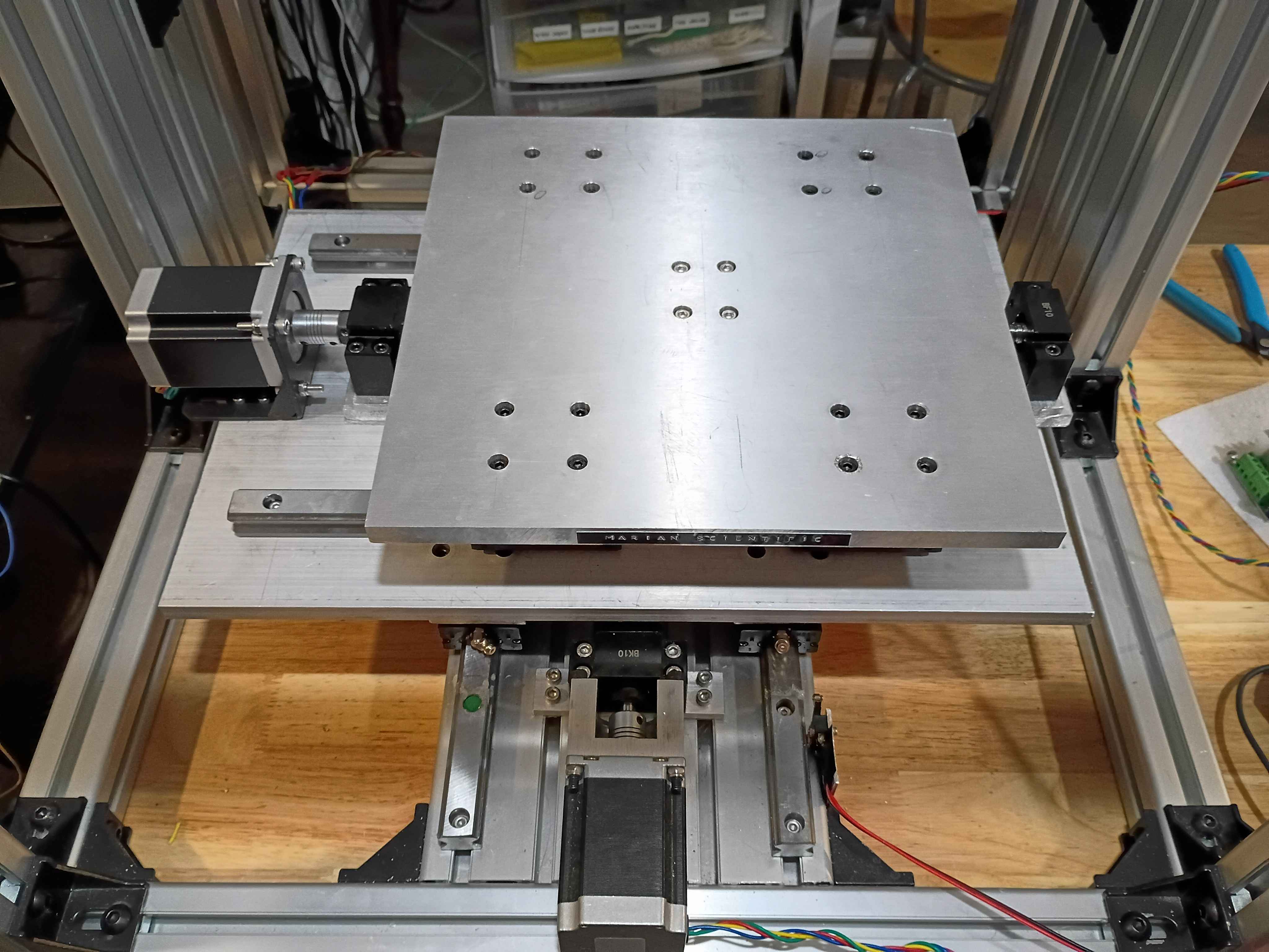
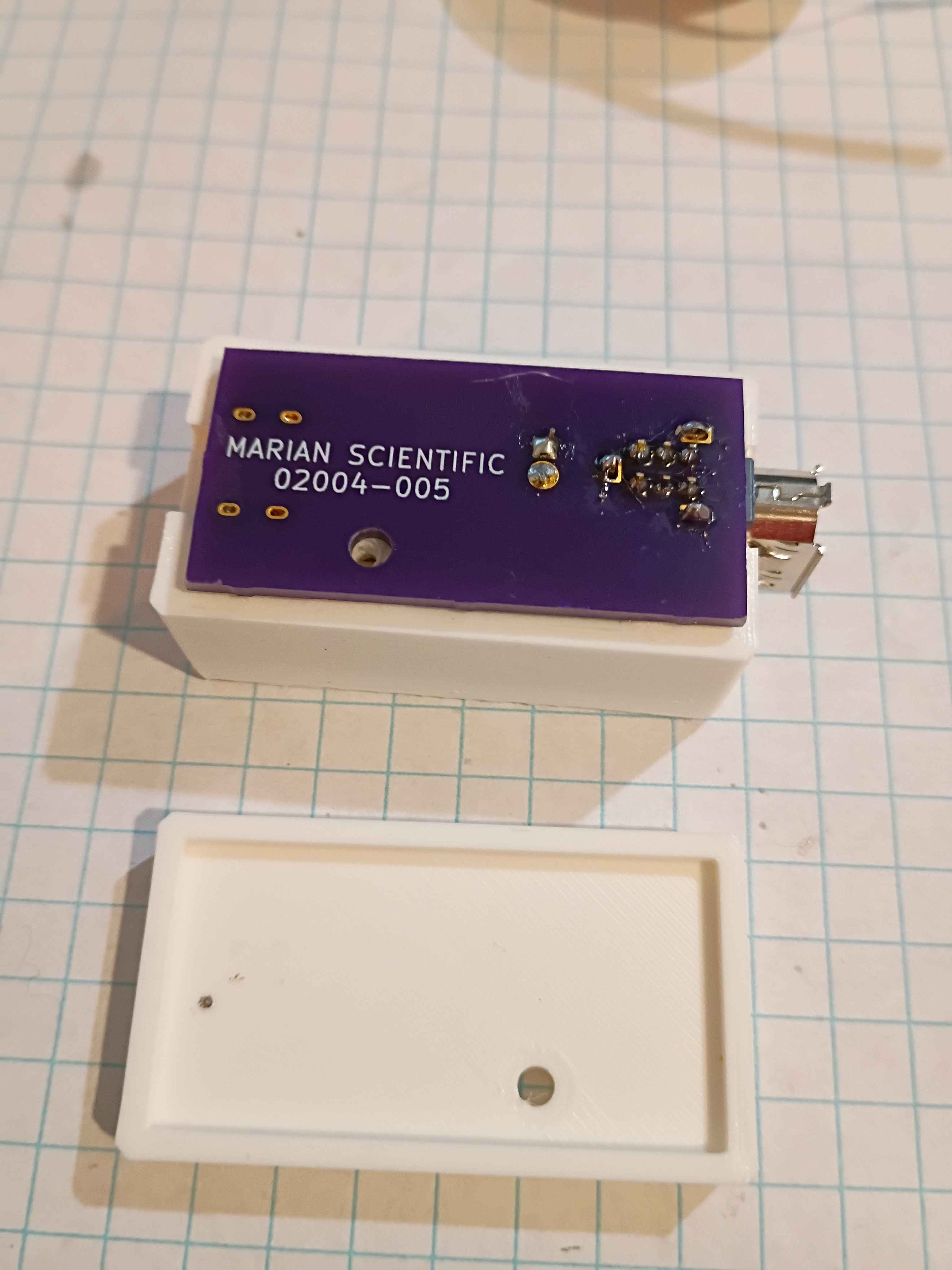
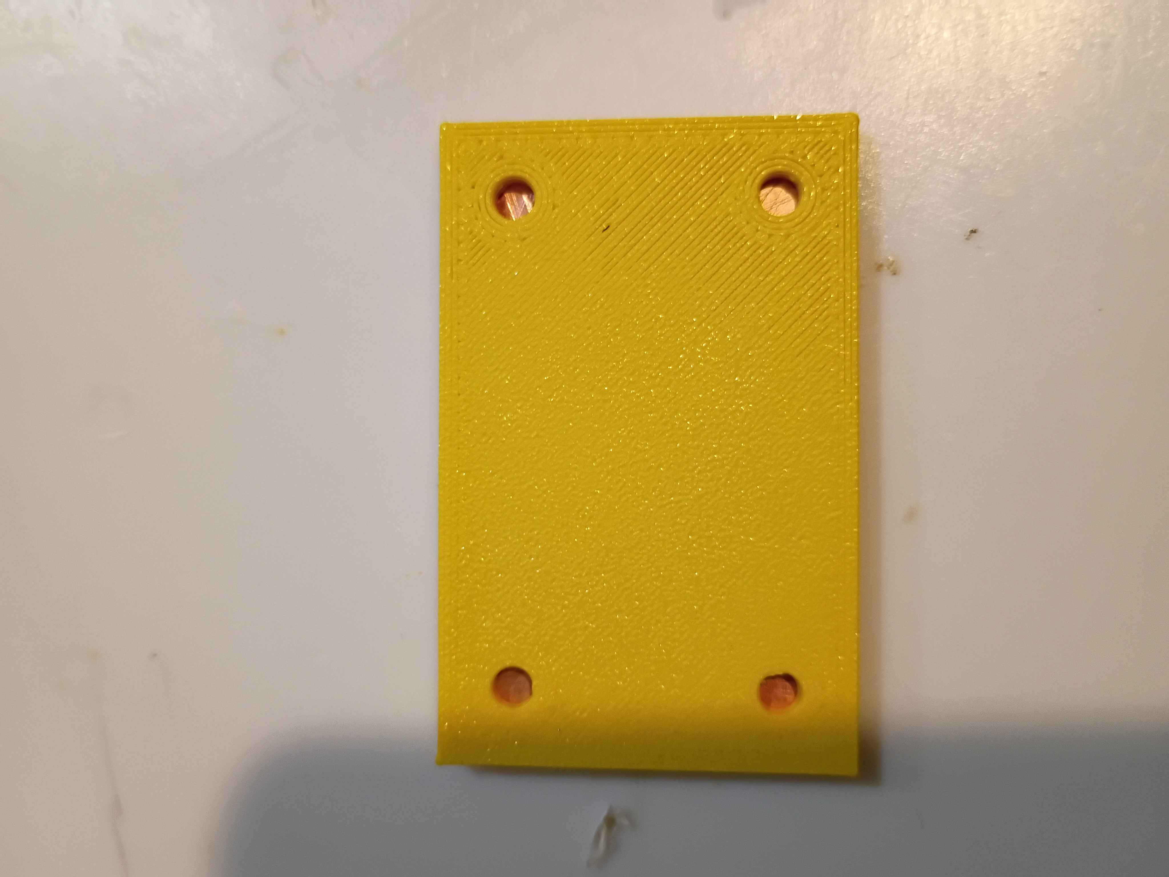
Redesigned 02004-007/008 assembly for the final time and printed 2 copies of each. Installed the 02004-005 PCBs. They actually work surprisingly well, though there is still a slight seam visible between them. 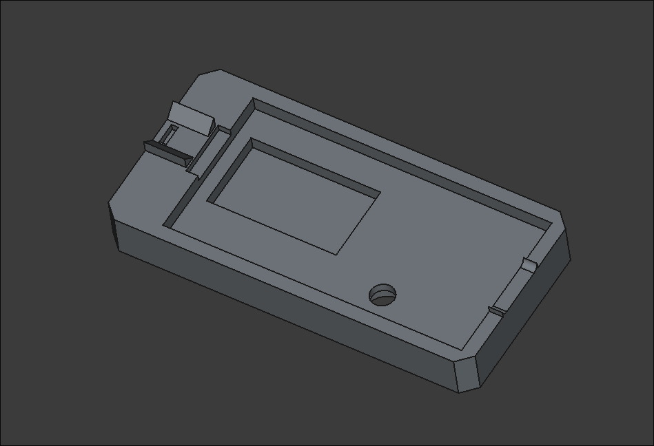
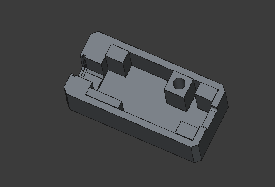
Added a dab of CA glue to the FireWire and USBC thru hole contacts for additional support. Revised and reprinted two iterations of the housing assembly out of ASA. I think I need one final reprint of the smaller piece with a slightly deeper recess. 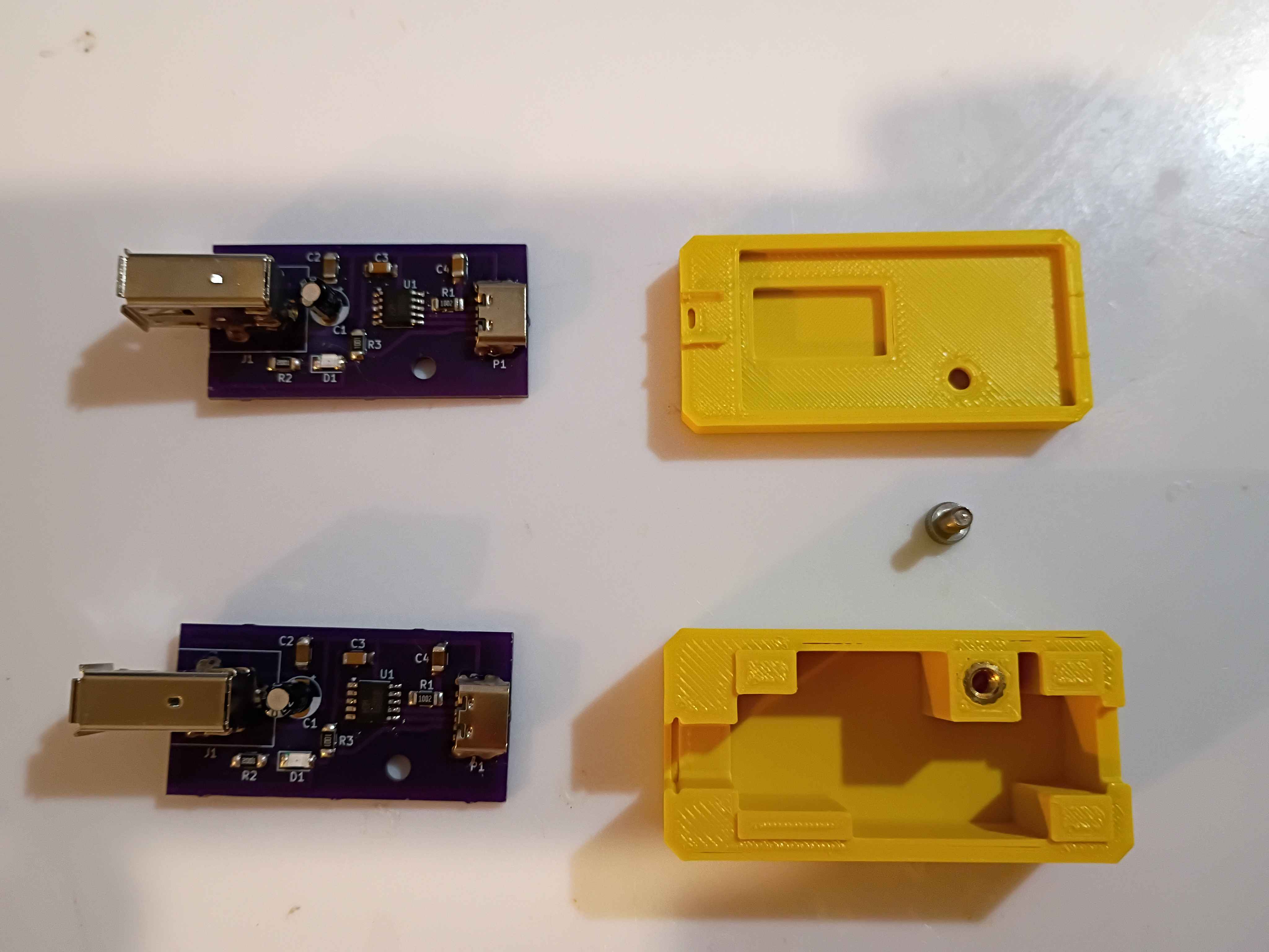
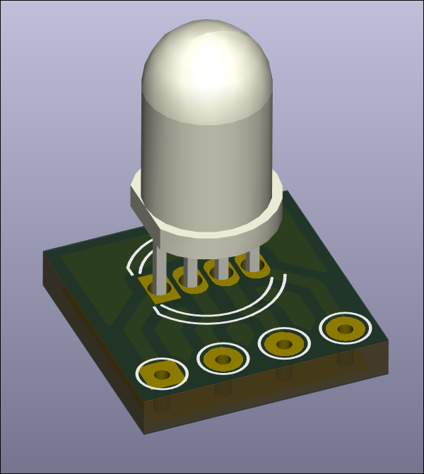
Designed RGB LED mount and breakout board for in-house fabrication. Board size is 10x10mm. 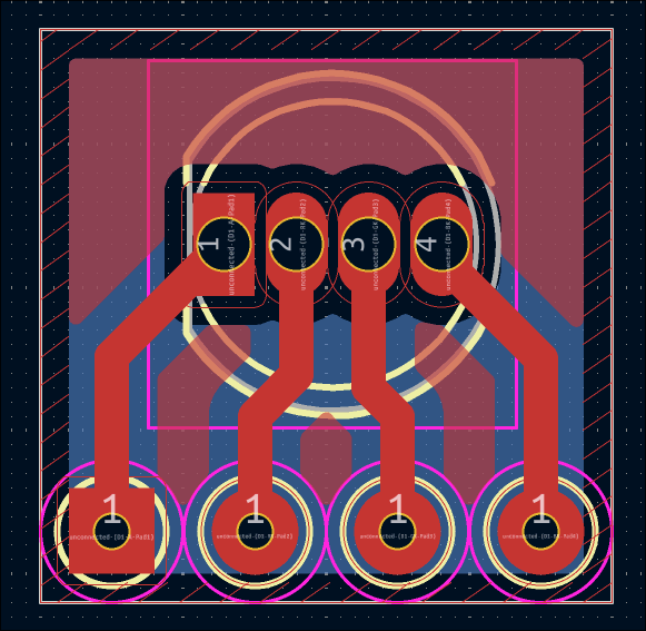
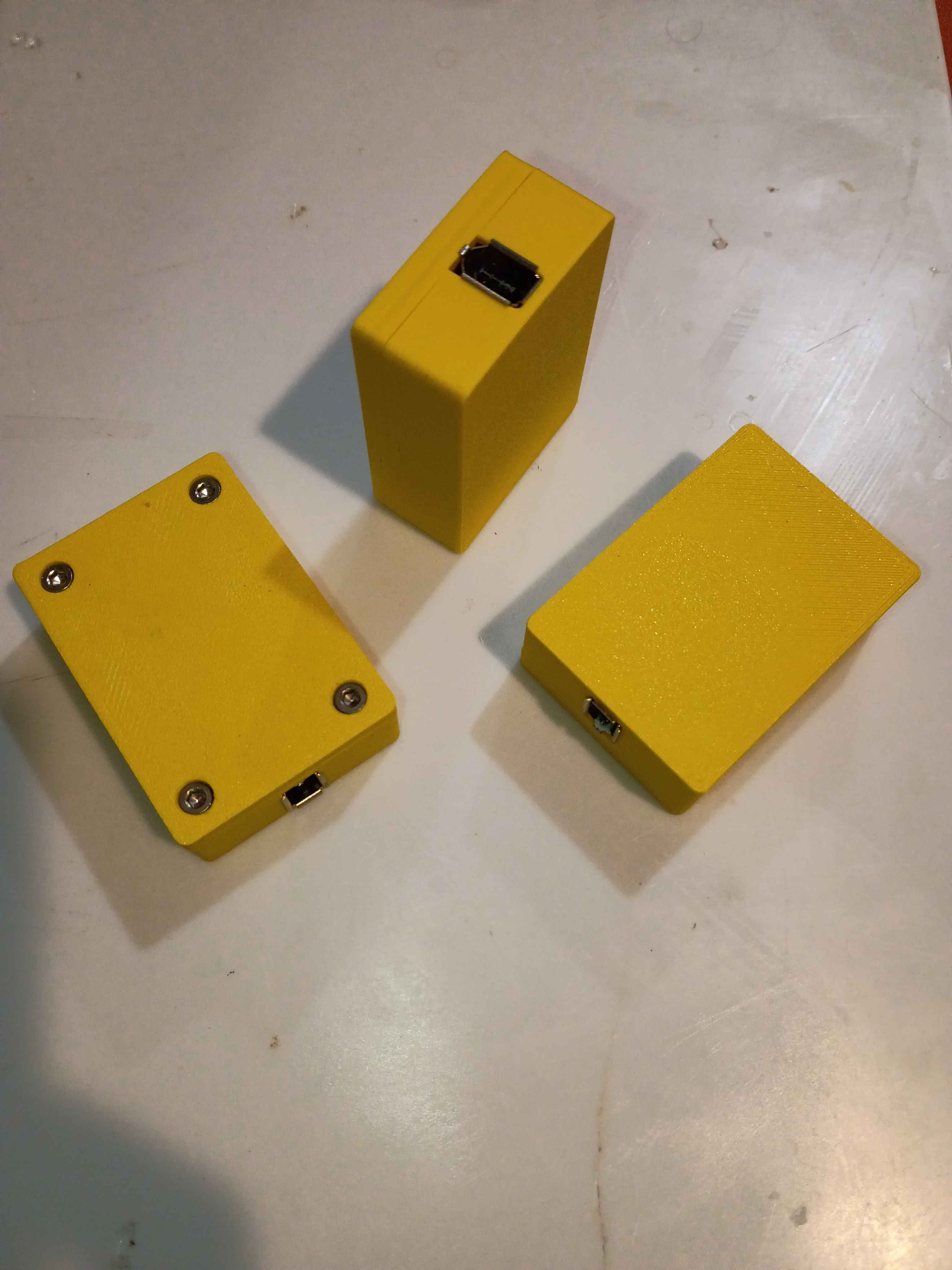
Successfully soldered and tested 2 more boards. Redesigned the housing based on lessons learned from the first box prototype yesterday. Parts are printing overnight, and the assembly will be tested tomorrow. 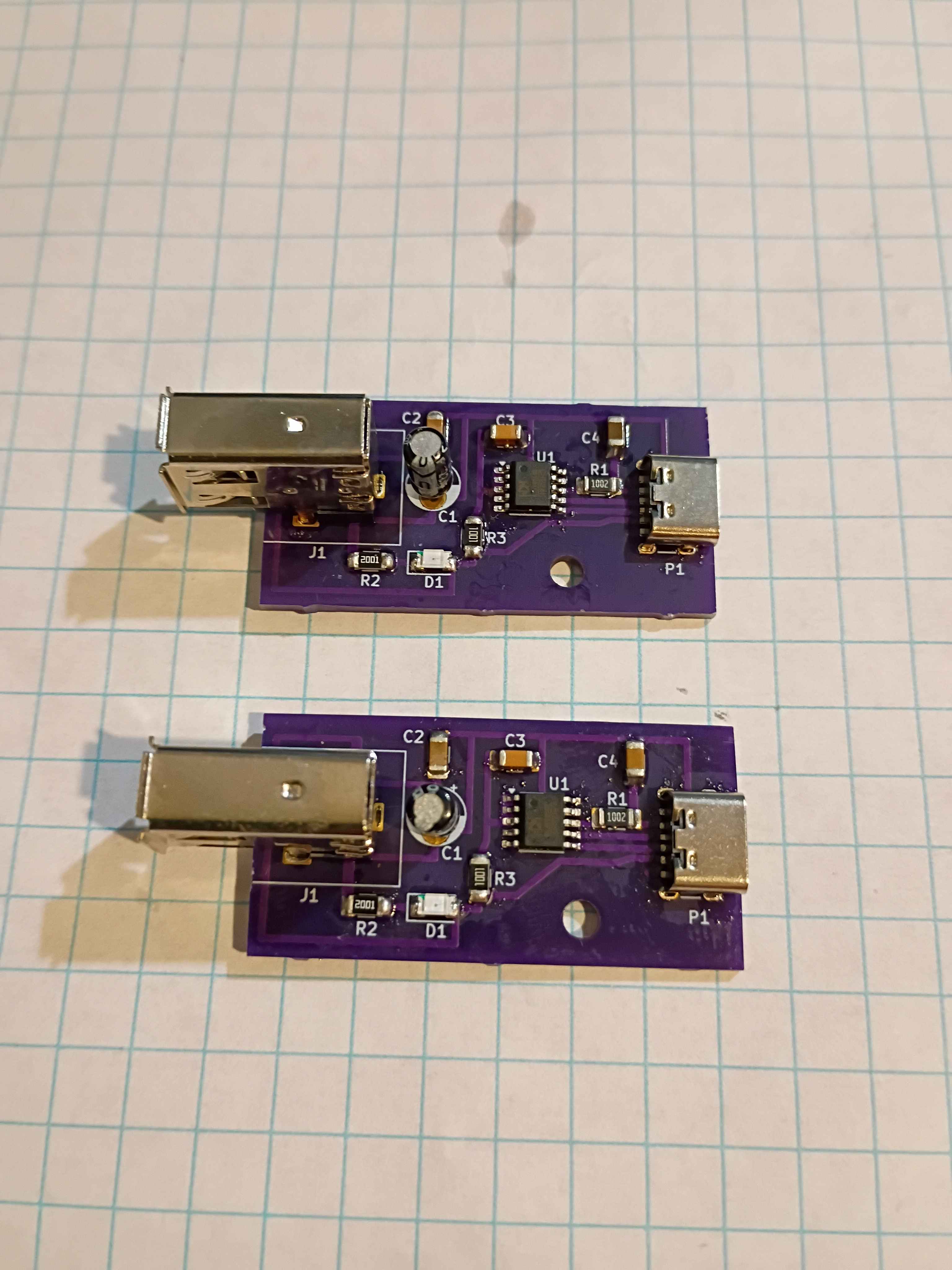
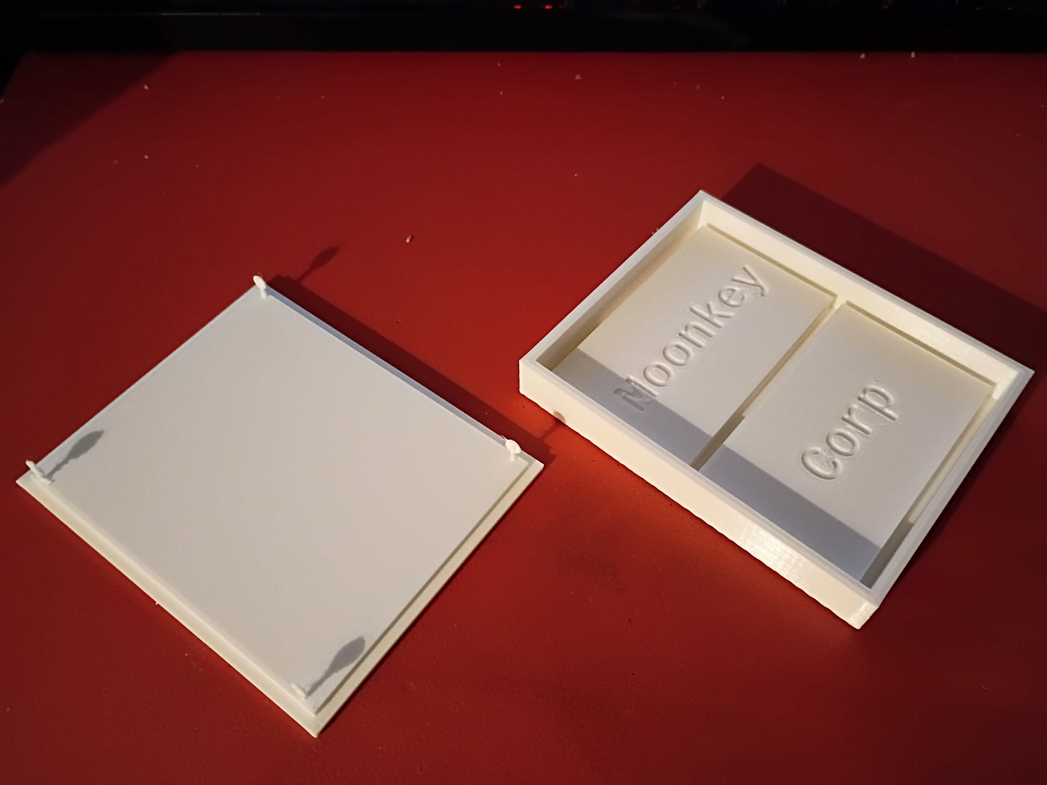
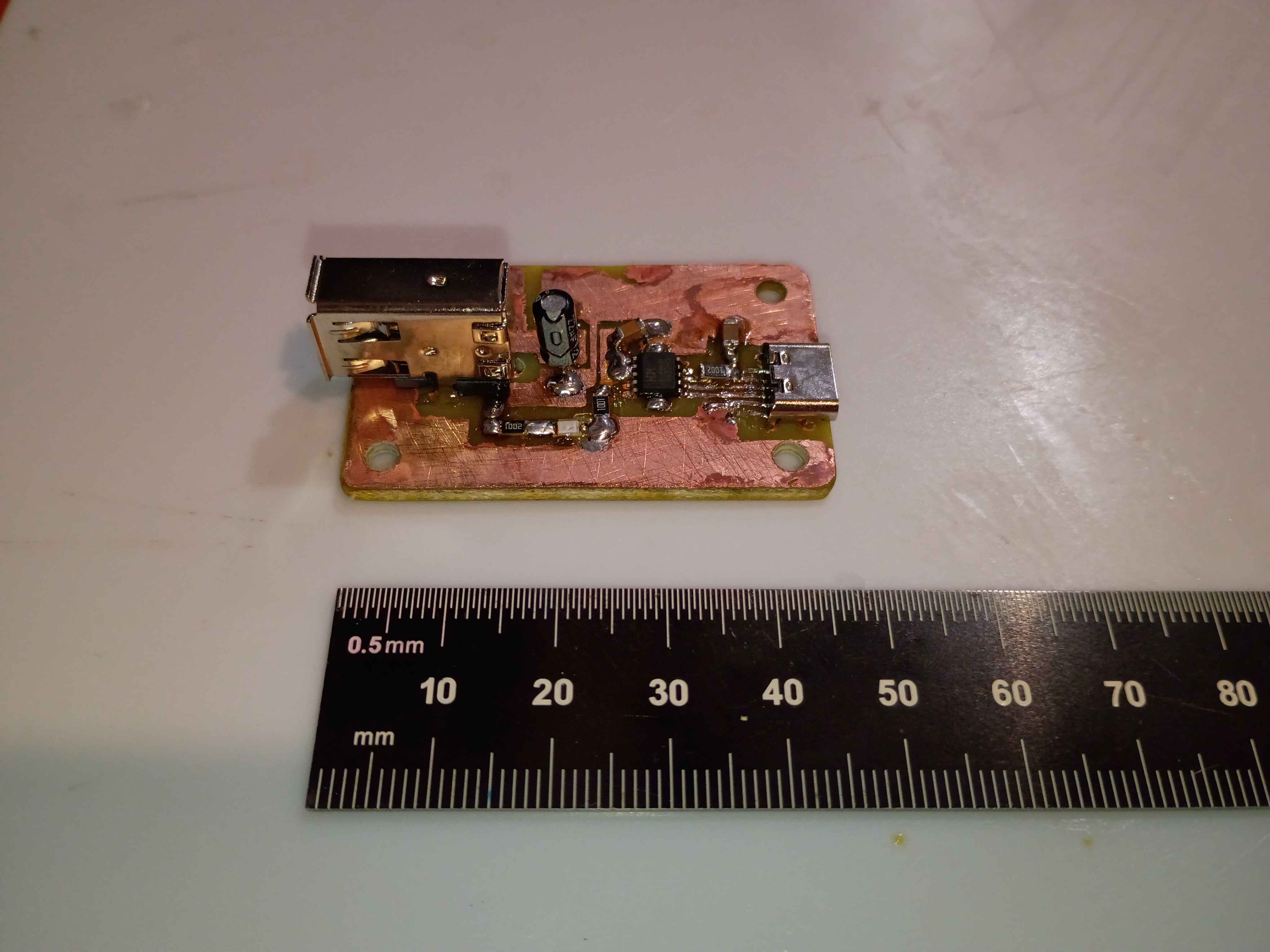
Received 02004-005 PCBs from OSHPark. High quality, as usual, but took 7 business days, with the fastest processing and 2-day shipping, plus 2 weekends. Still good in a pinch, I suppose. Designed and printed a 2-piece housing, though several details will need to change before it works perfectly. Used hot plate for the first time to solder most of the components, which went pretty well, and did the FireWire and thru-hole capacitor by hand. I think some components (including CH224K) were shorted because I put too much solder paste, so ultimately I had to scrap the first board, though I have 2 more to try. 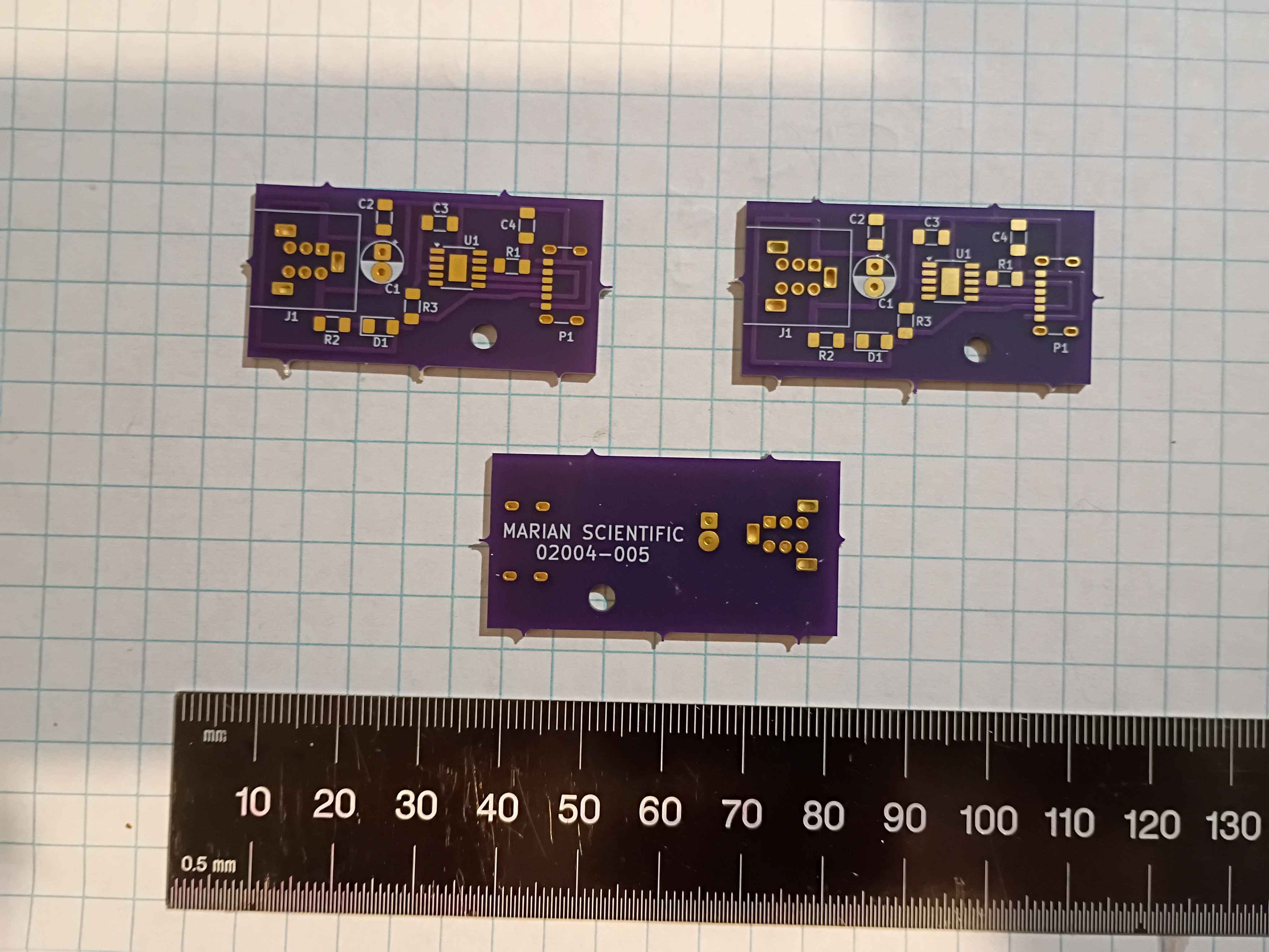
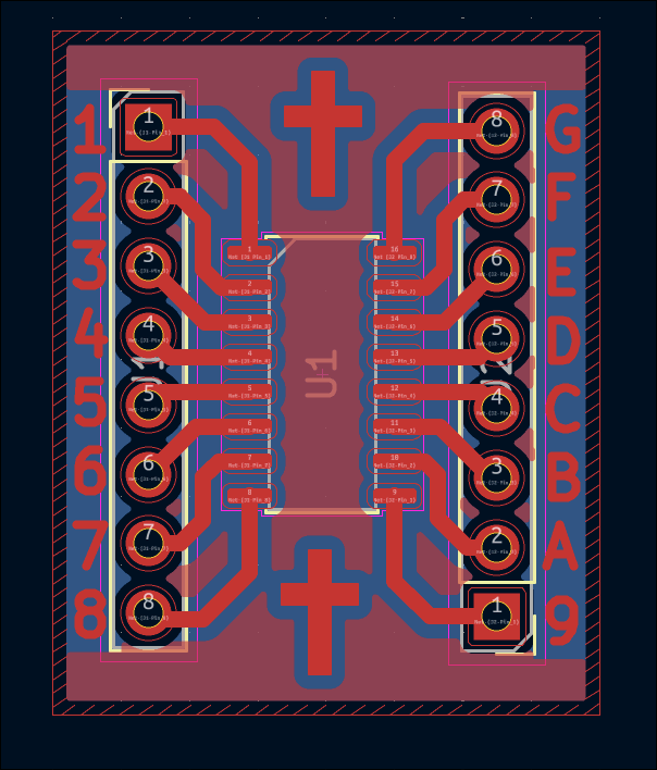
Designed breakout for ESSOP-10 IC. This is designated for testing purposes on a breadboard. 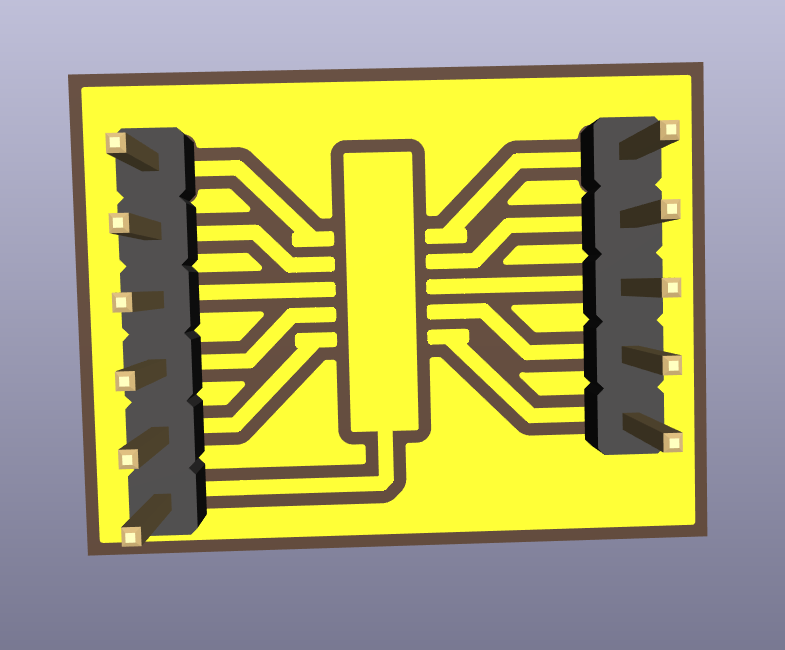
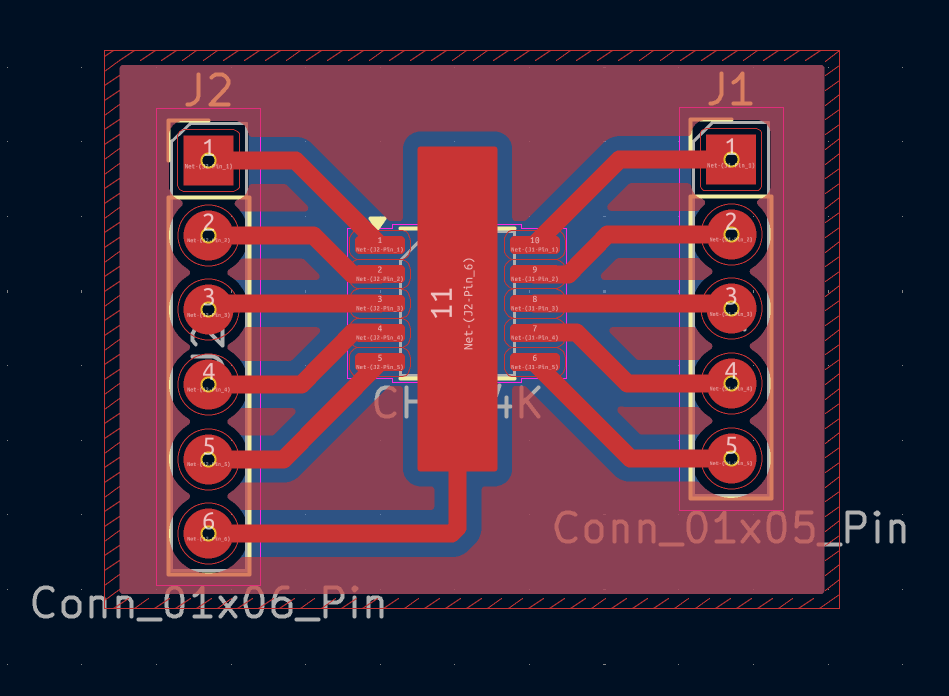
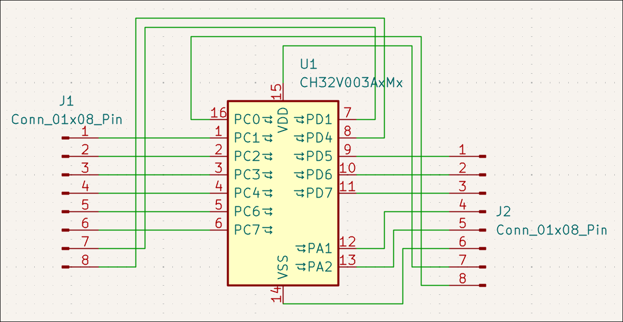
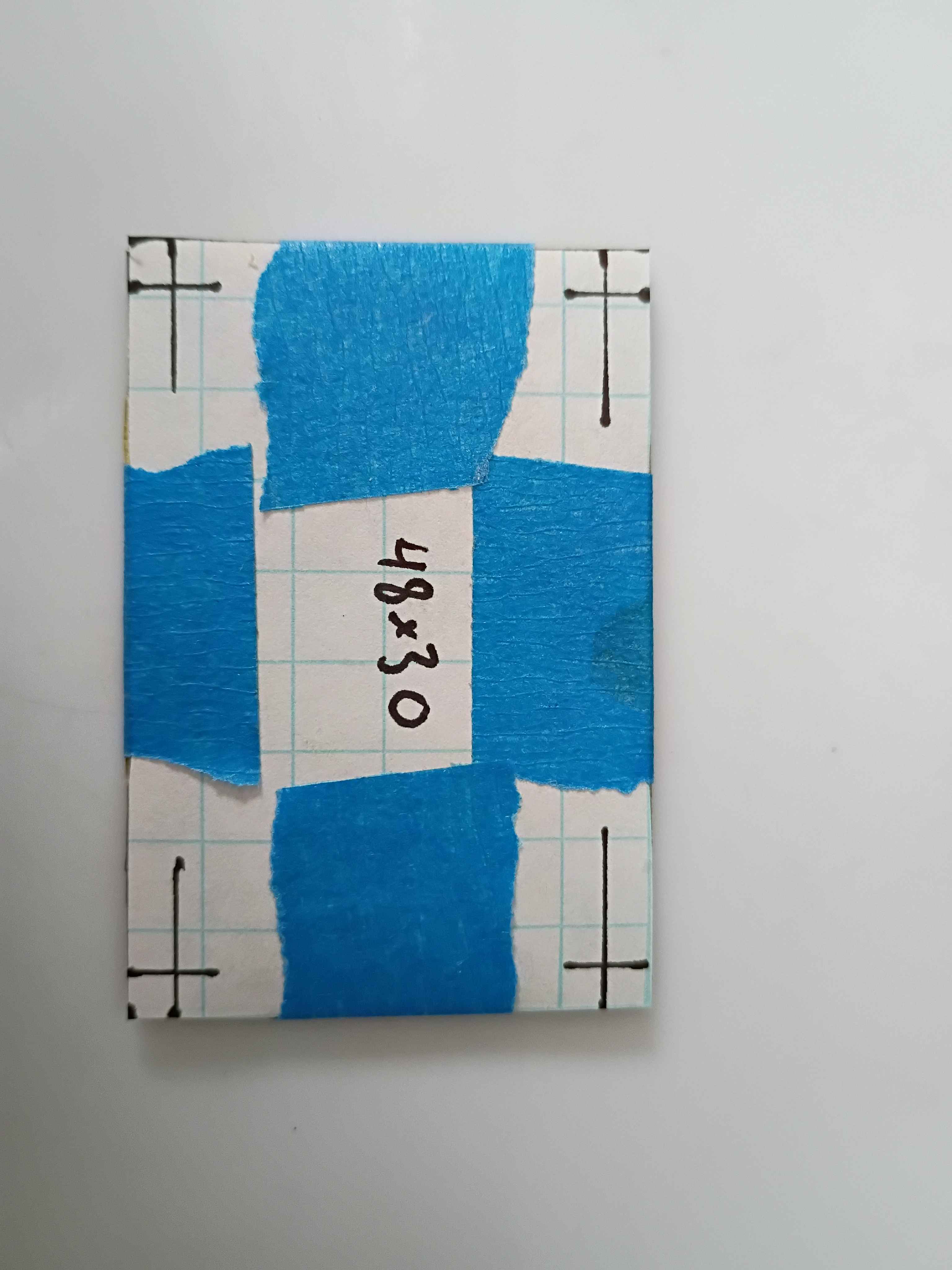
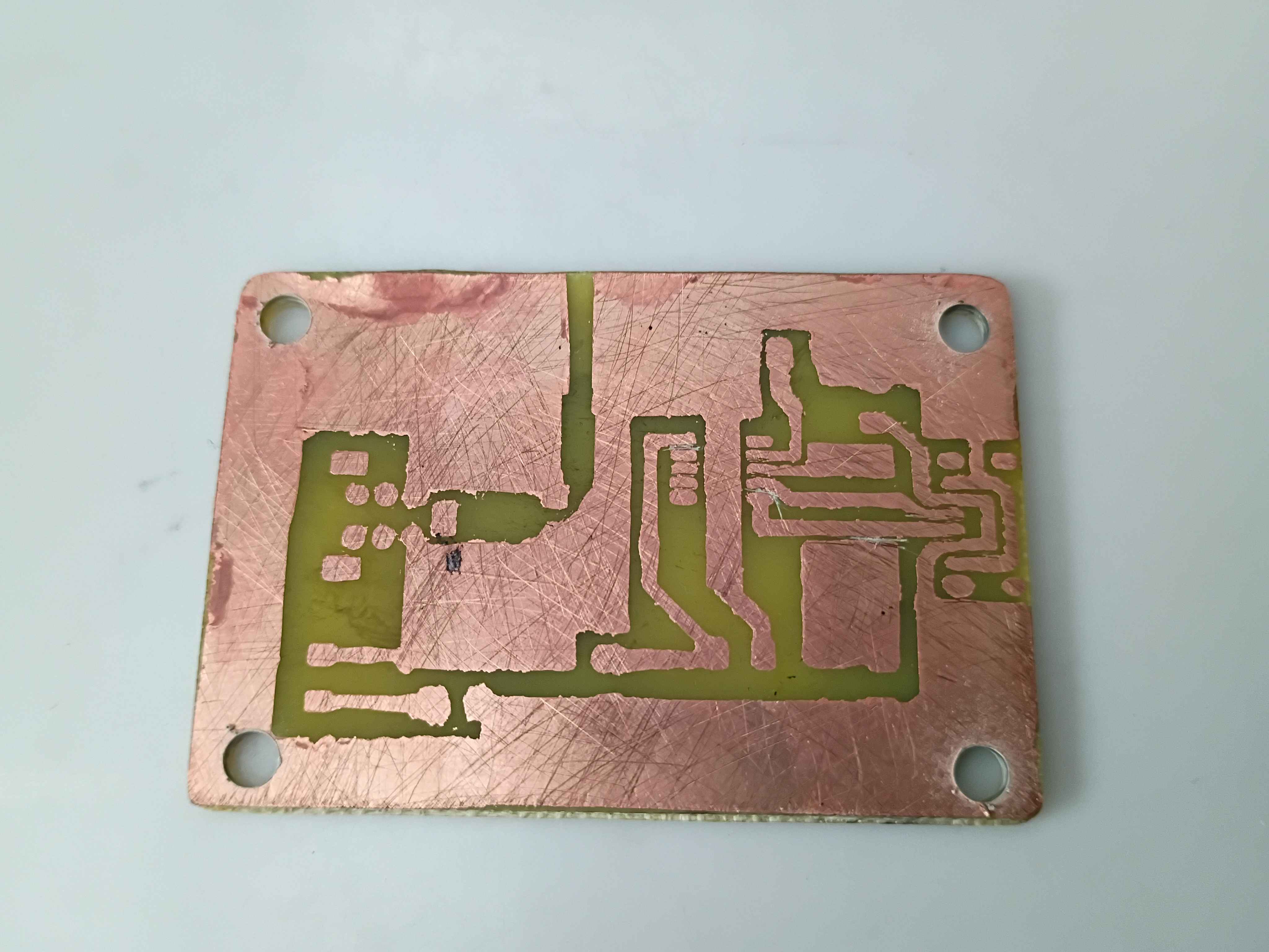
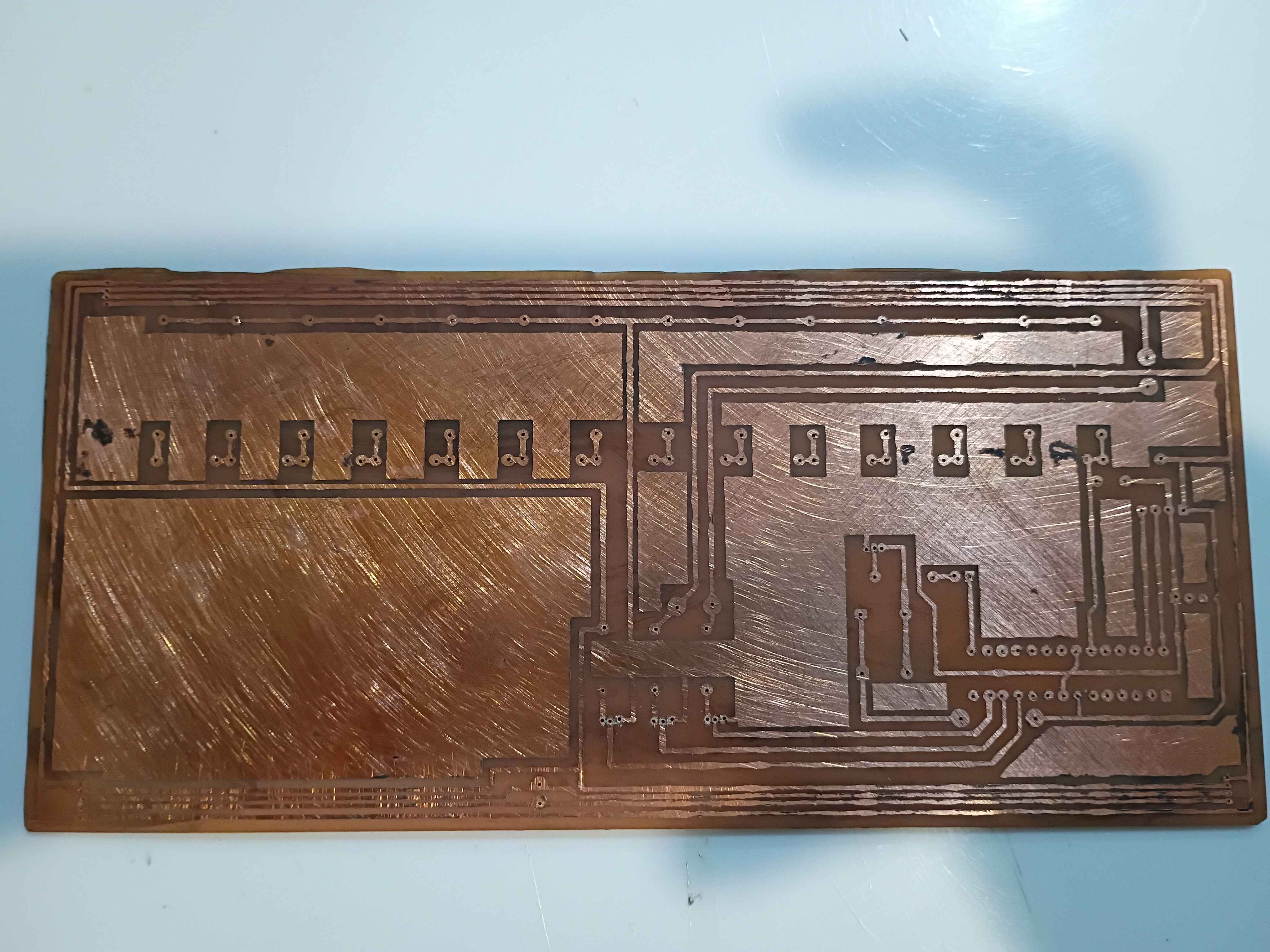
Designed breakout PCB for generic 16-SOP IC (in this case, for the CH32V003A4M6 MCU). As a test, embedded some crosses and text in the copper layer to attempt that. This is for testing of the IC to be used for the stepper motor controller. 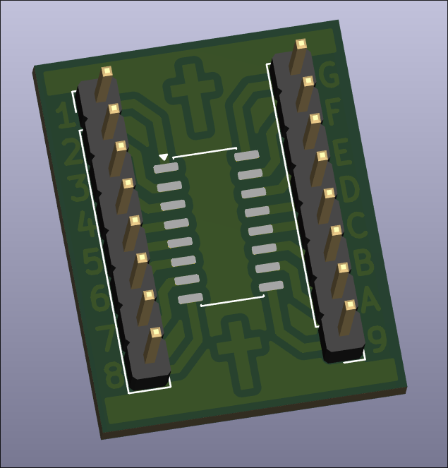
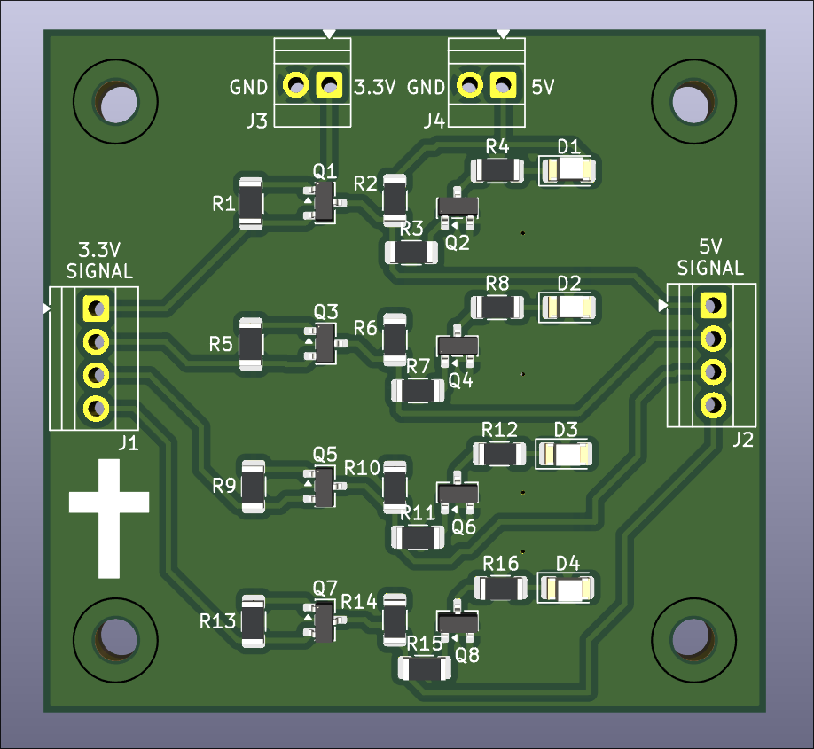
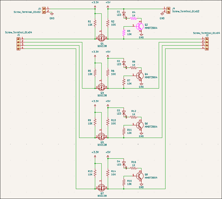
Created logic-level-shift PCB design with built-in LED indicators and ordered on OSHPark. 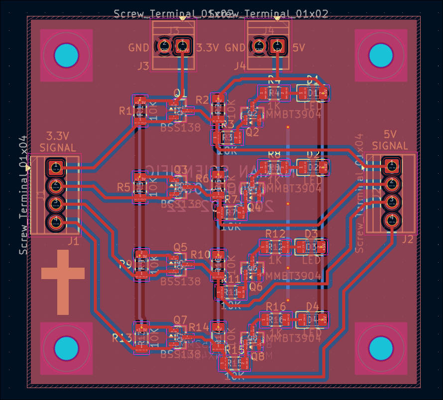
Cut, drilled and installed shims under the gantry plate. Also reversed the 2 upper mounting screws on the y-axis stepper. Altogether that gives roughly 110mm of motion. I will have to drill out some of the holes a bit wider and possibly straighten the rails because currently there is some binding in the Y-direction motion. 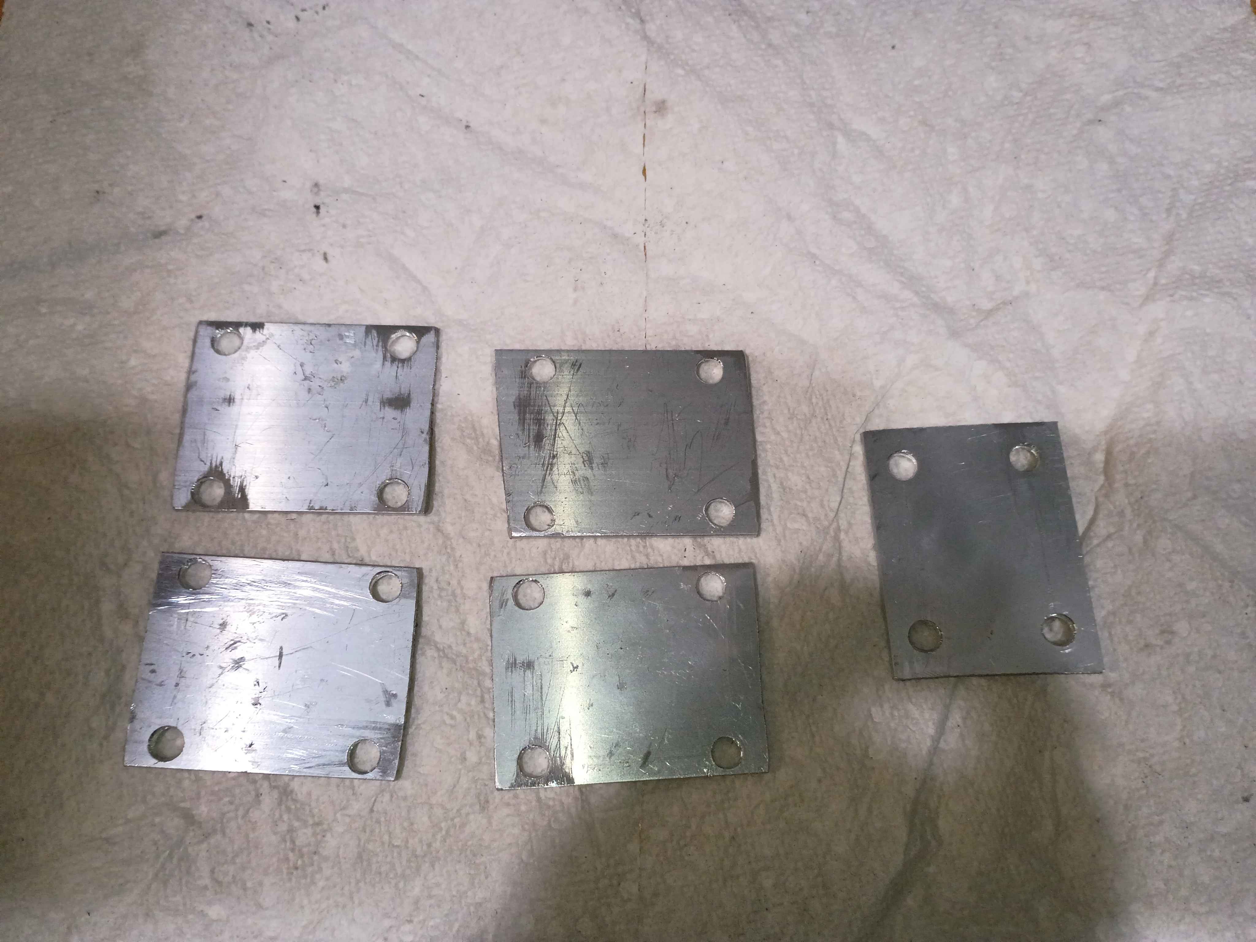
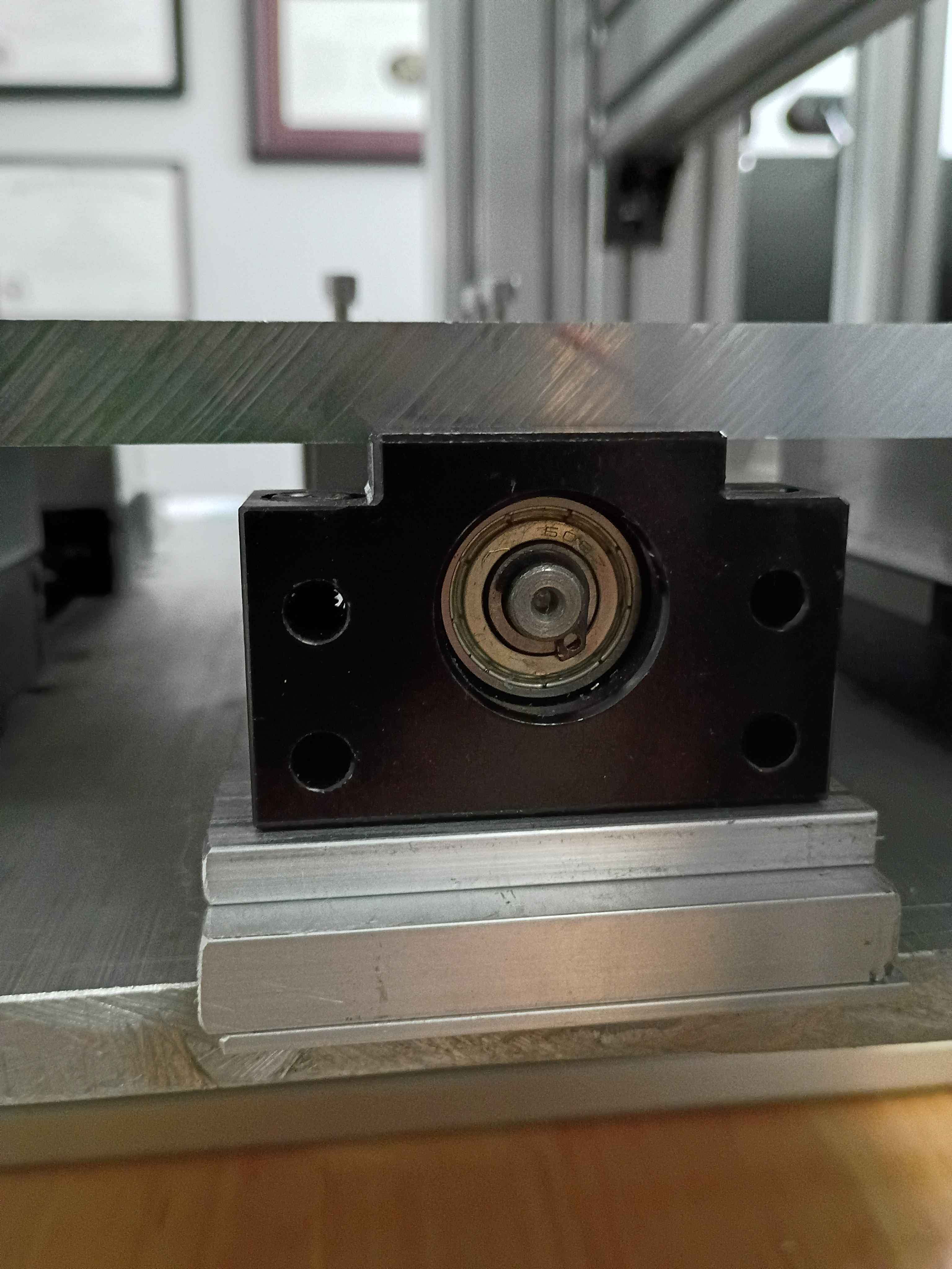
Installed gantry plate successfully, but apparently there is insufficient clearance with the ballscrew support blocks for more than 1 inch of motion in the Y-direction. I will need an additional 2mm shim on all carriages and possible 3mm on the ballscrew follower nut. 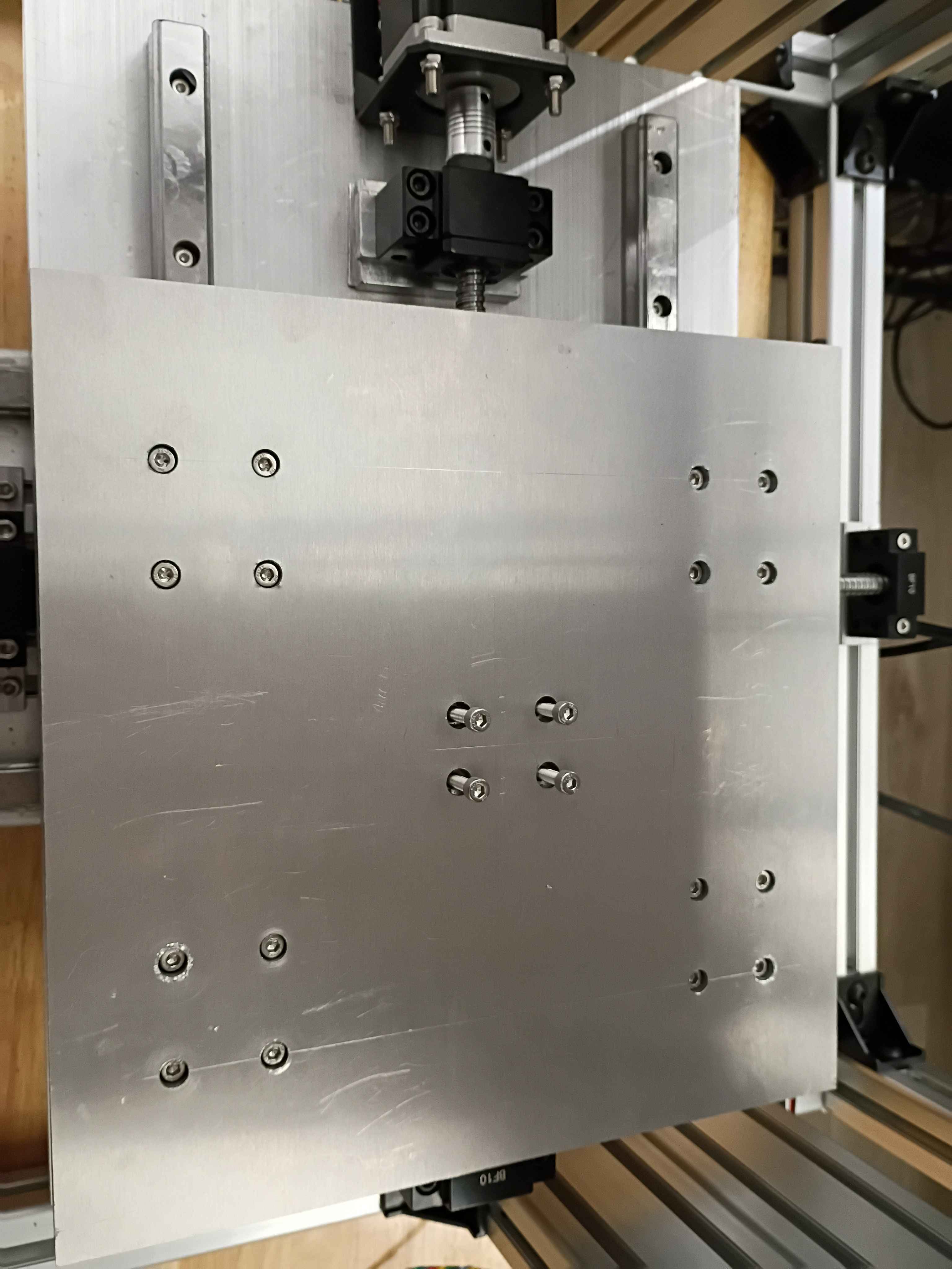
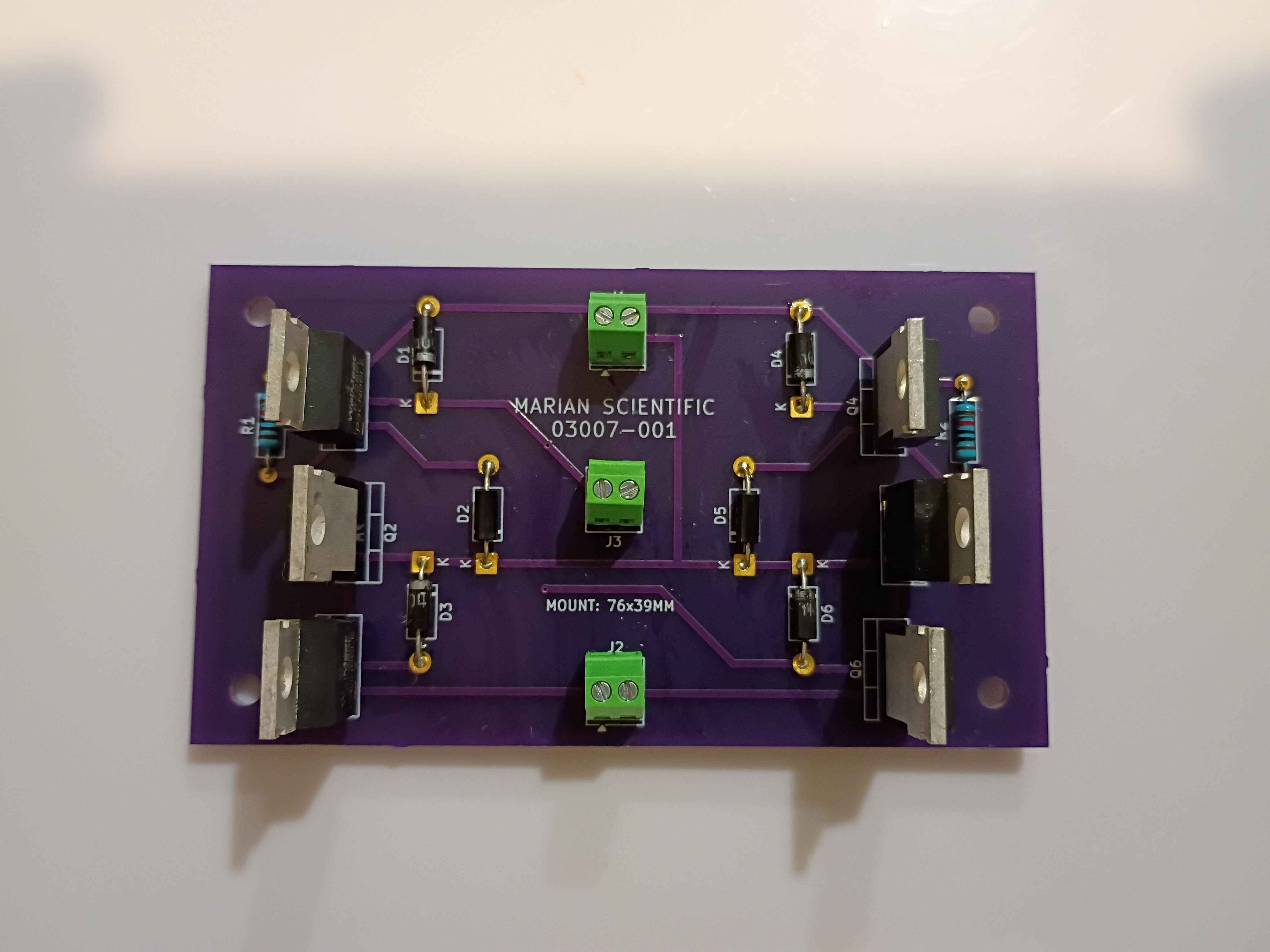
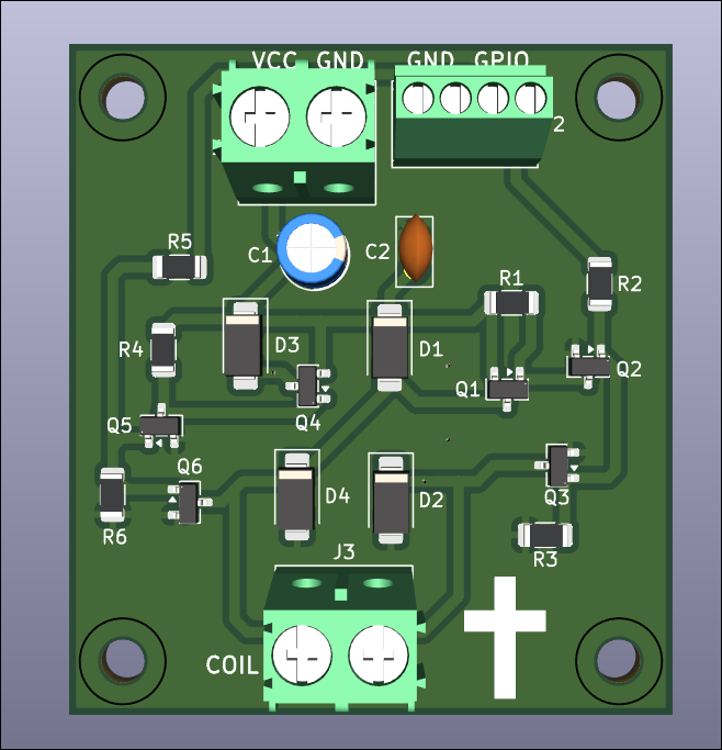
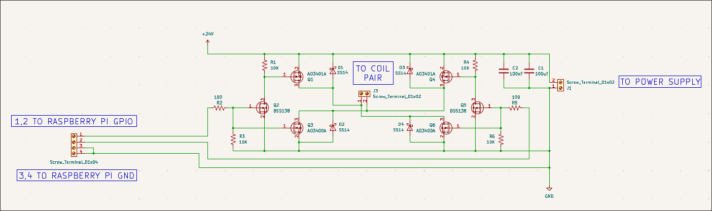
Created 03007-003 PCB design for a single H-bridge stepper driver using SMD components. Submitted board for fabrication at OSHPark, though this could technically be fabbed in house. 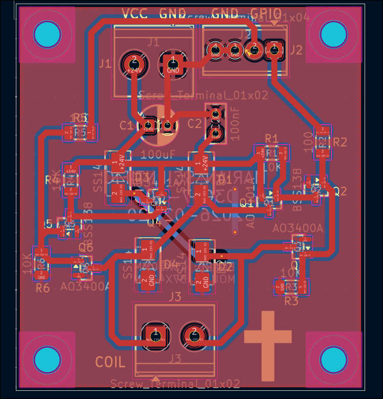
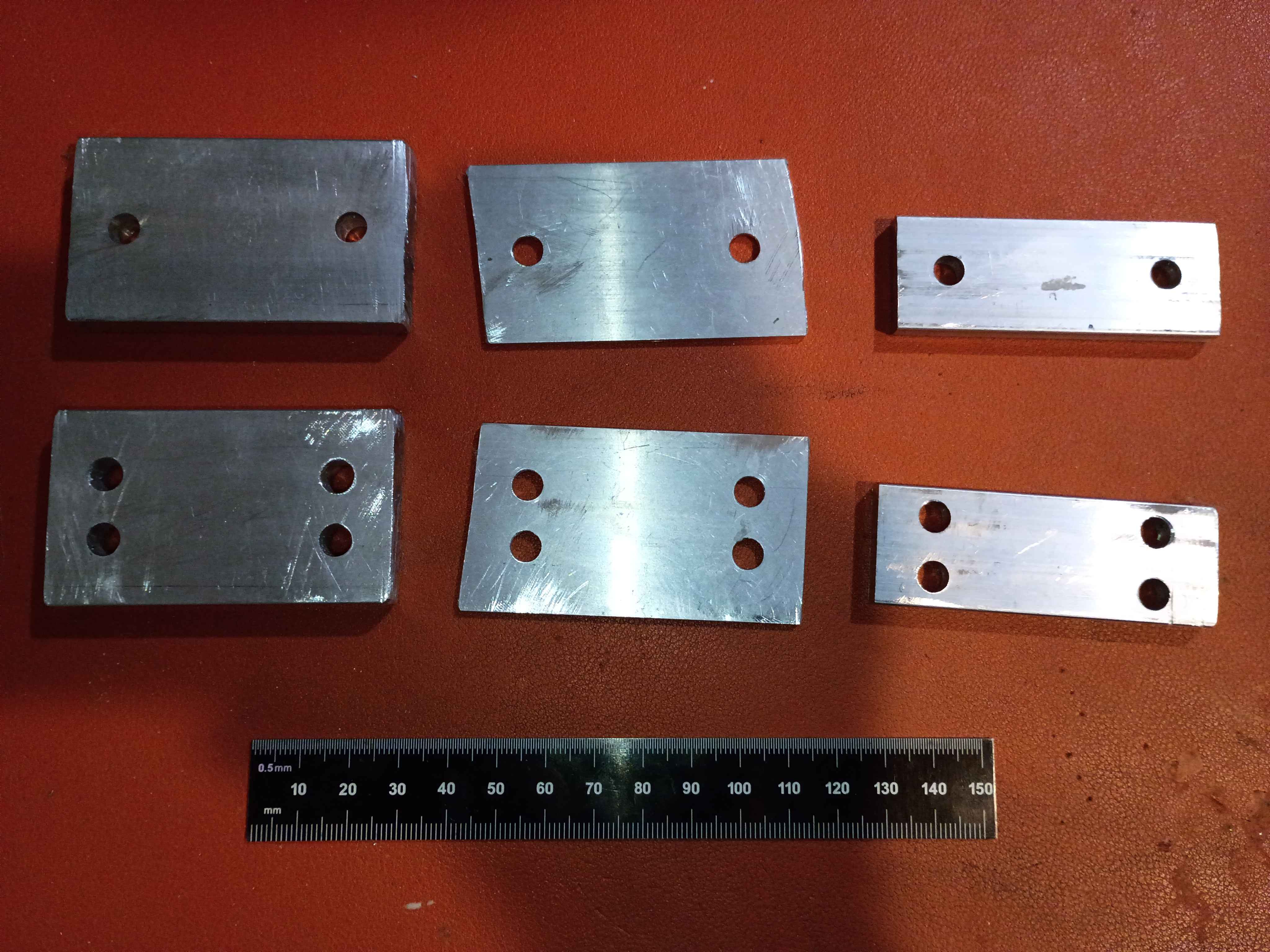
Cut, filed, drilled, and deburred 4x linear rail carriage mount spacers for the y-axis motion system. Ordered the corresponding length screws to mount the gantry plate.
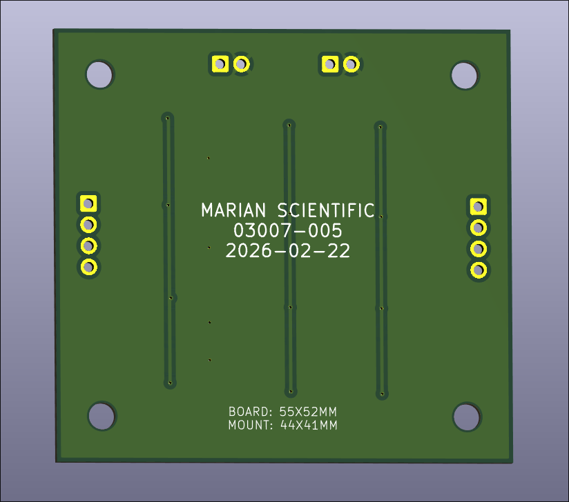
Created a Marian Scientific KiCad project template that has a basic PCB with mounting holes, the minimum silkscreen info required per company standards, and a bunch of settings set up for both an in-house and professional board fabrication. Click here for the template. 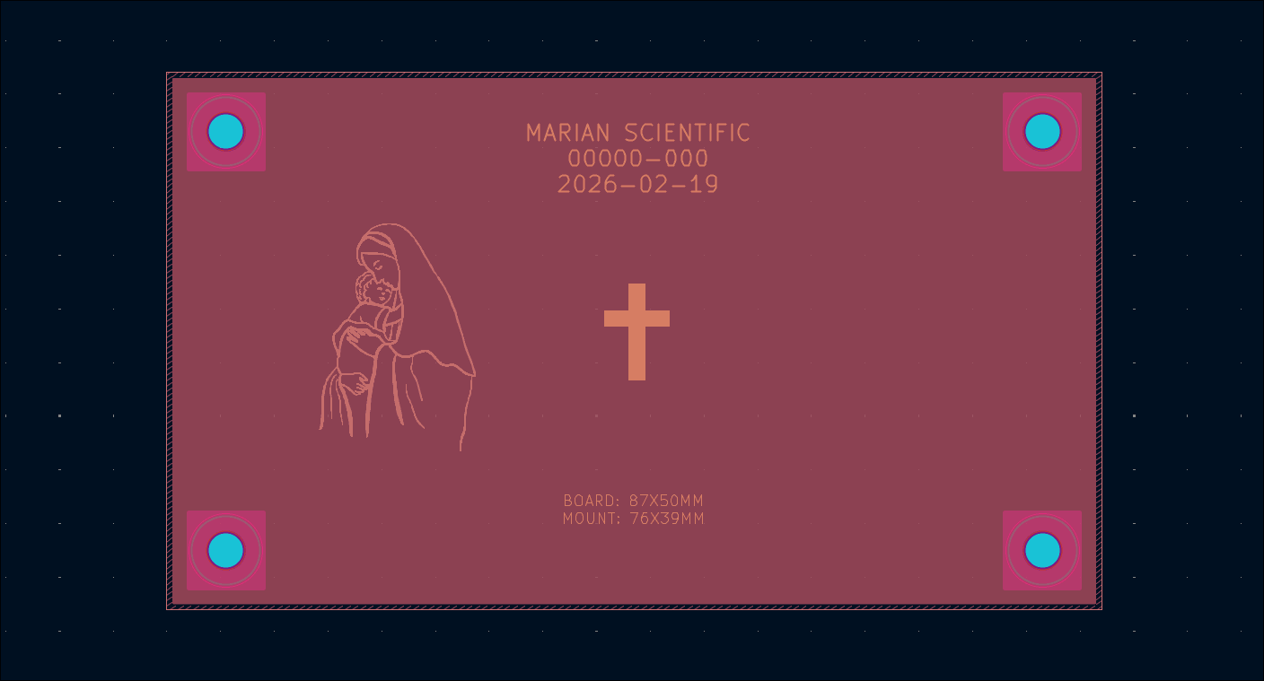
Reversed the diodes on the first soldered board and retested, which still showed a short. Realized I had some of the P and N channel MOSFETs installed in the wrong spots. Would have been good to label them on the silkscreen. I just soldered 4 other boards with the correct components and they seem to work, though I have not fully tested them all with coil loads. I did not have enough P-channel MOSFETs so I reused some old (potentially shot) ones. I have marked them to help identify them if an issue arises in the future. I updated the schematic and PCB design to reflect these revisions, rolling the part rev to 03007-001-A. It counts as a revision, not a new part number because the board has the same form, fit, & function as the sibling -001. 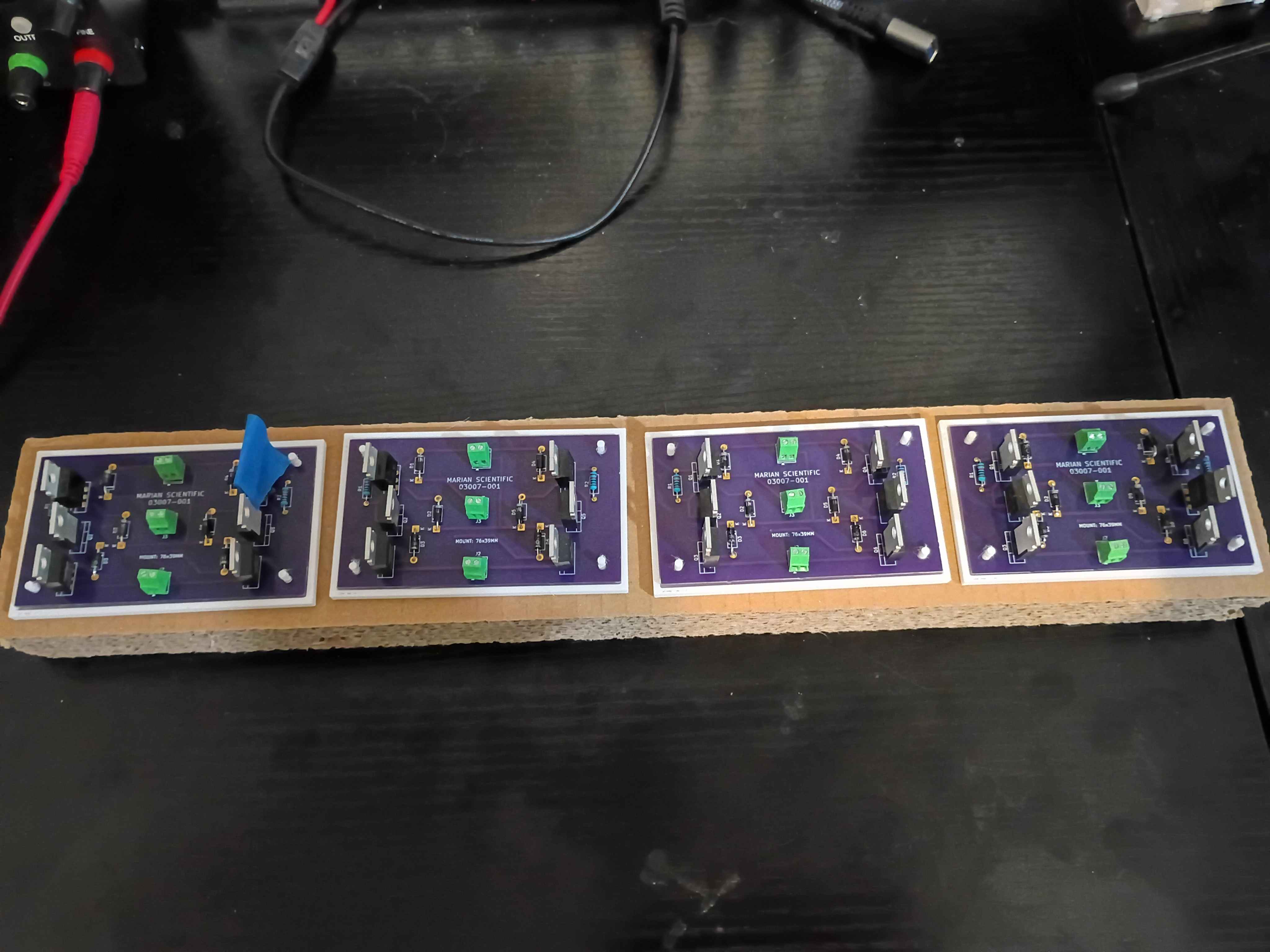
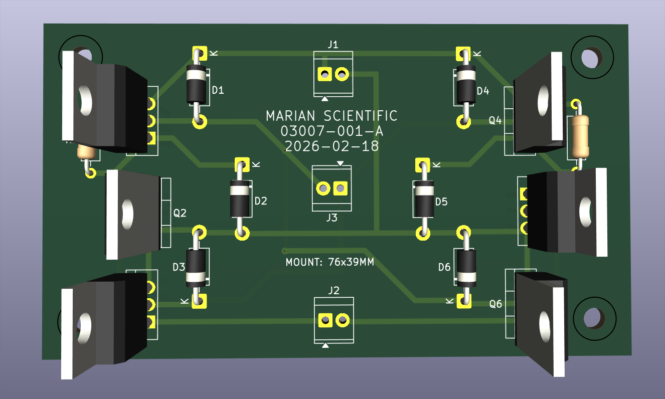
Printed a set of 4 PCB holders and began to electrically test the first board. After some debugging, realized that the schematic and front silkscreen have the diodes going the wrong way, which I installed the diodes to match. These 6 components need to be desoldered and reversed and the board silkscreen design technically revised. 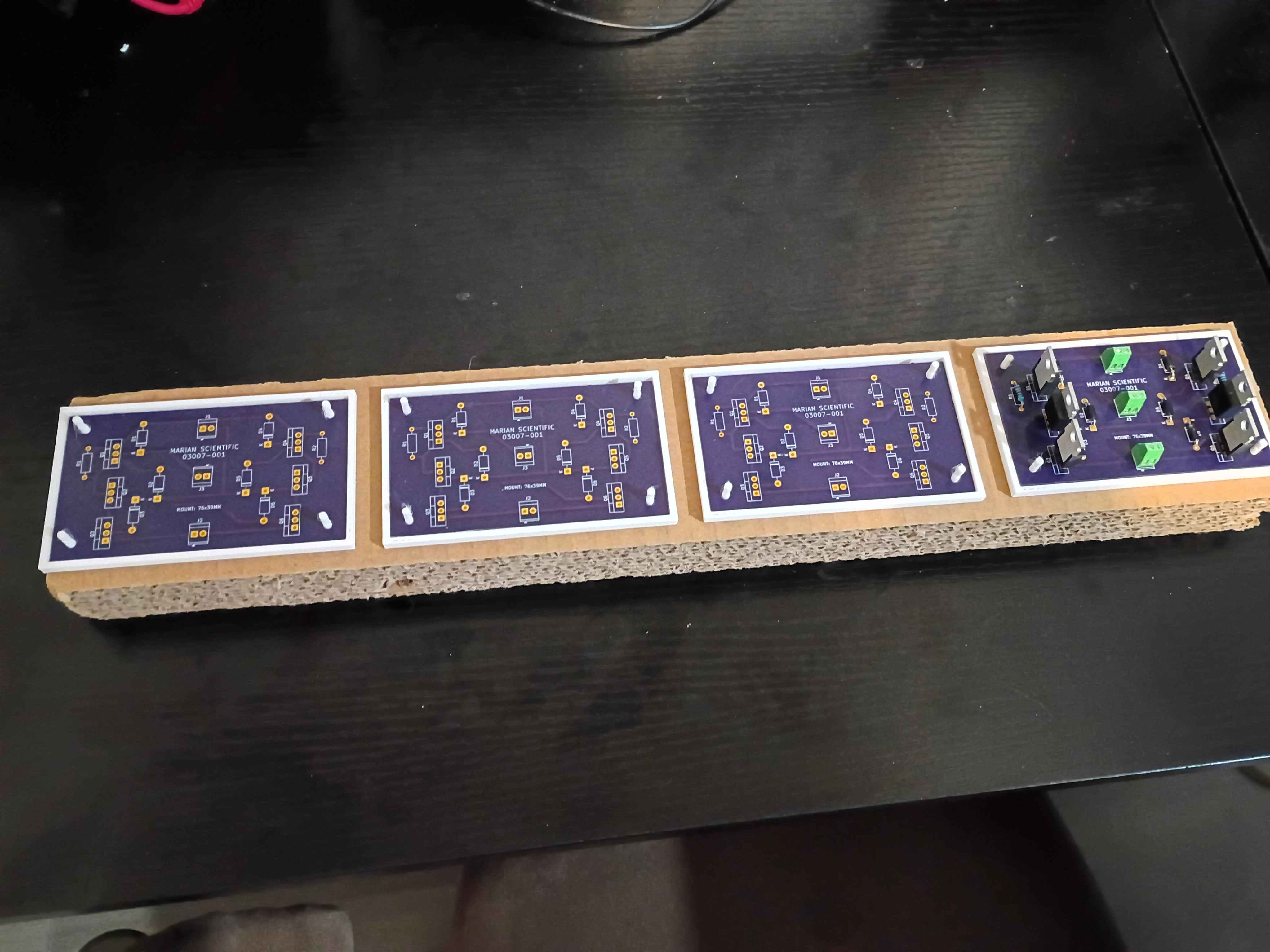
Bolted down Y-axis ballscrew supports, installed lubrication nipples, vacuumed the entire assembly, and lubricated the rails and screw. 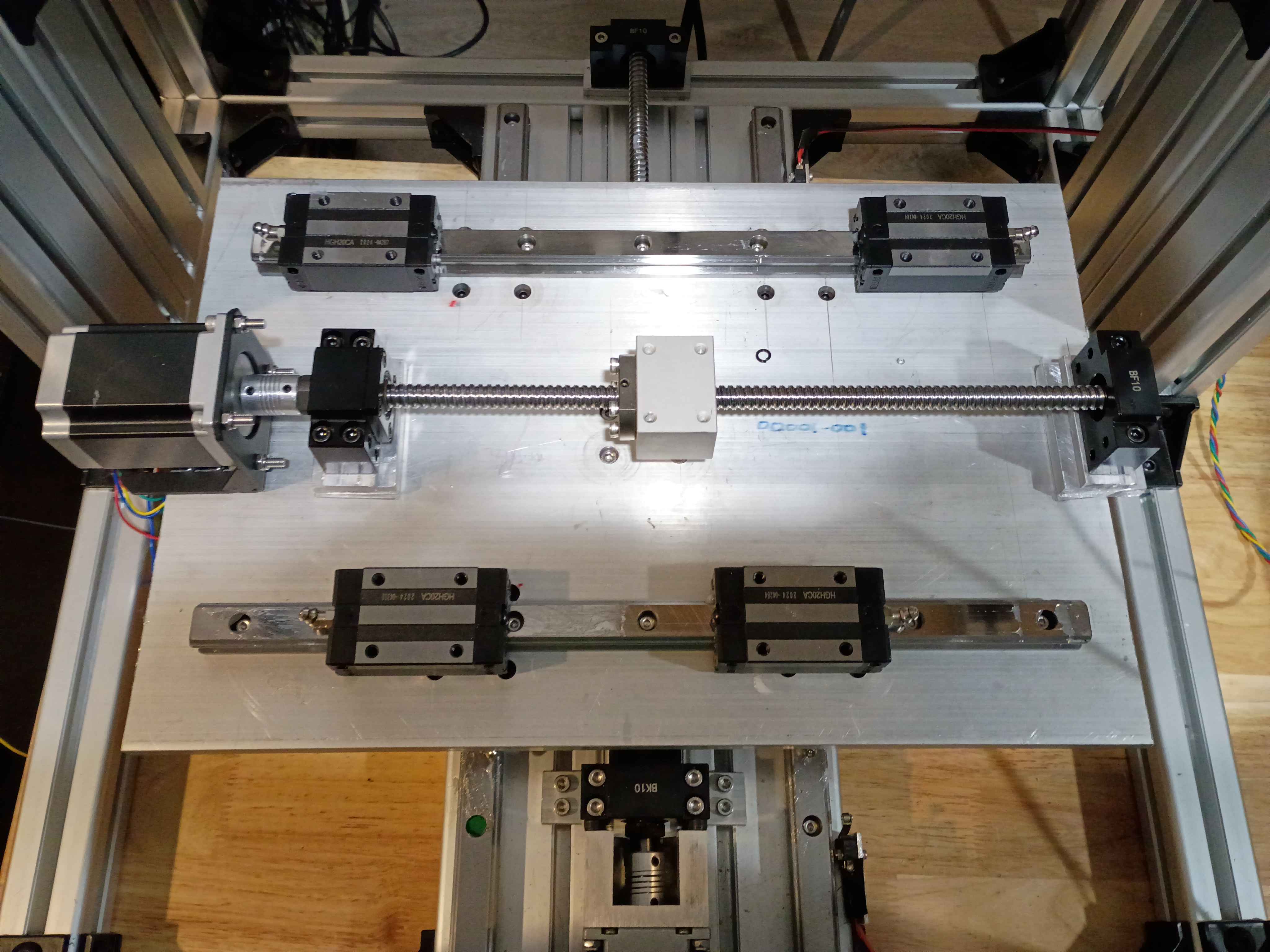
Removed silicone mat from the tool and installed edge magnets. Overall the proof-of-concept was a success, but in the future I would like to use thicker magnets set in a thicker wall and with a vent hole in the upper mold tool somewhere to prevent leakage. 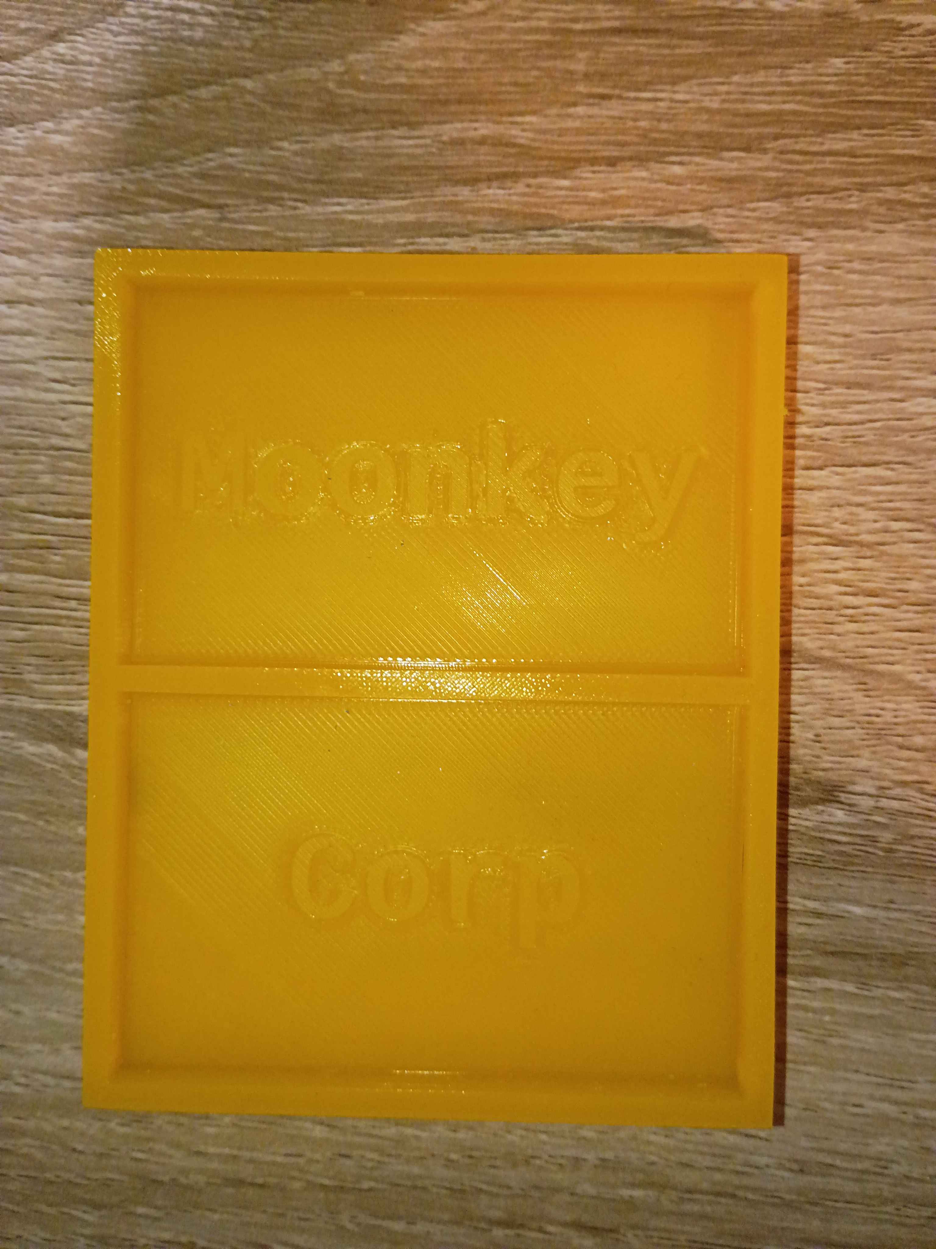
Installed ballscrew nut follower onto Y ballscrew. Determined height of linear rail carriage spacers (25mm ~ 1in) and ordered some aluminum stock for that purpose. Also printed templates for the clearance hole patterns. To simplify this process going forward, I spent some time configuring my network printers.
Modeled and submitted for print a holder for the 03007-001 stepper driver PCB. 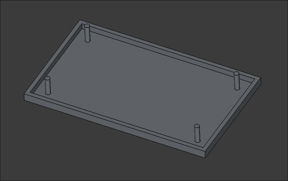
Cut, filed, and drilled clearance holes in some spacers for the ball screw support blocks for the XY gantry motion. Took a while to saw because my hacksaw blade is getting quite dull. Used Inkscape, my printer, and a gluestick for the first time in this application to actually mark out the drill locations, which worked swimmingly. I do need longer M5 bolts to mount these, however. 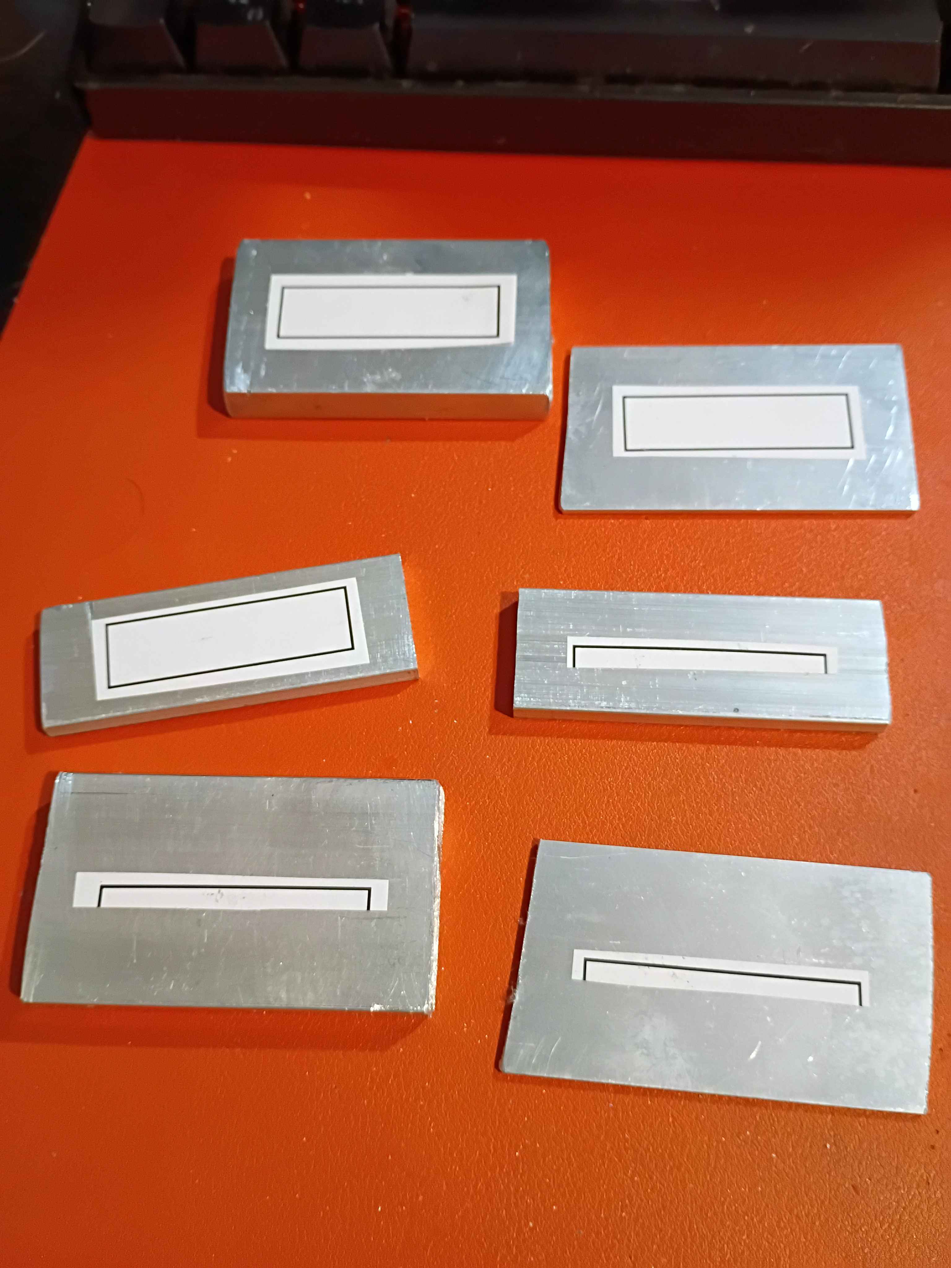
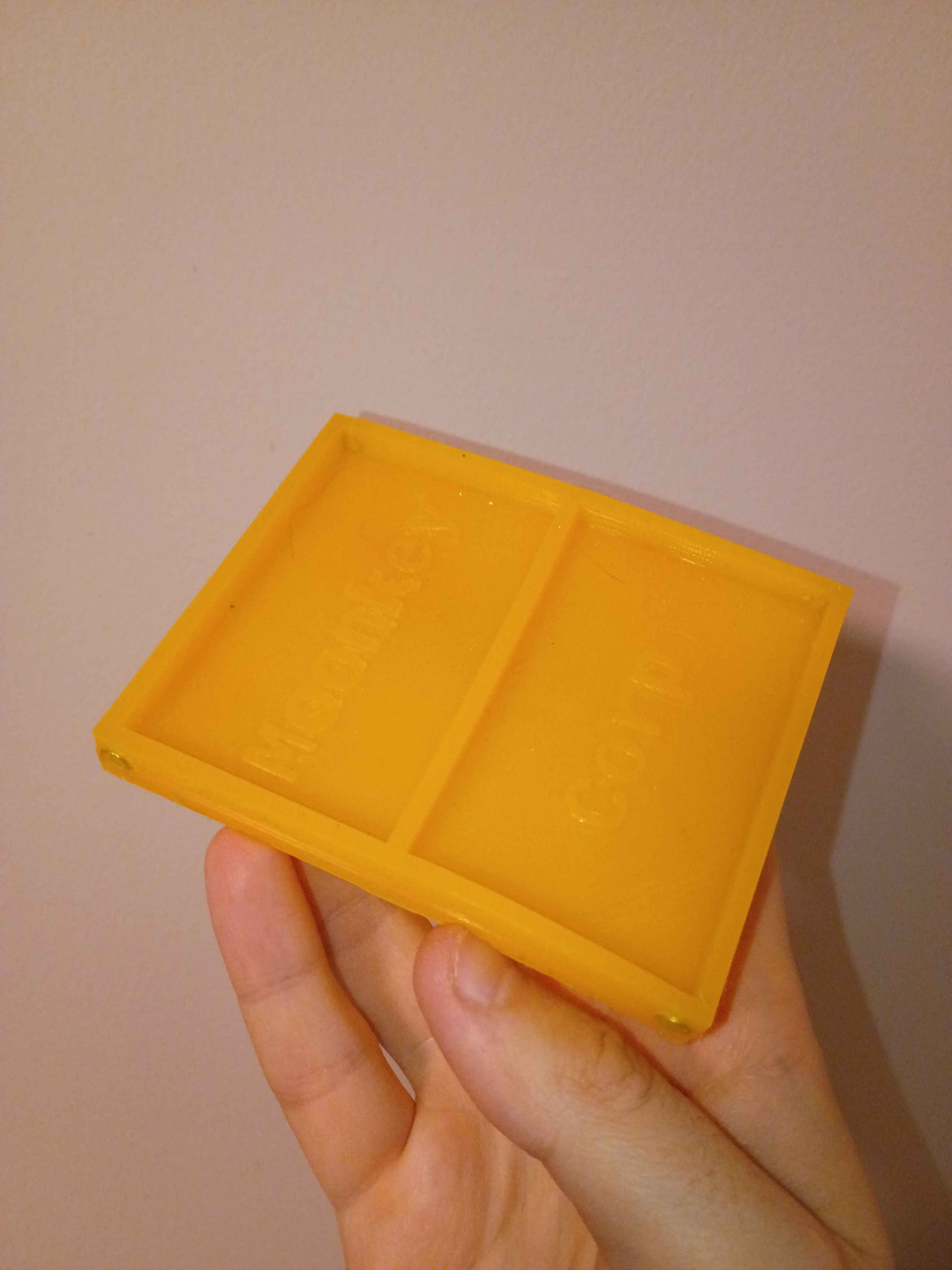
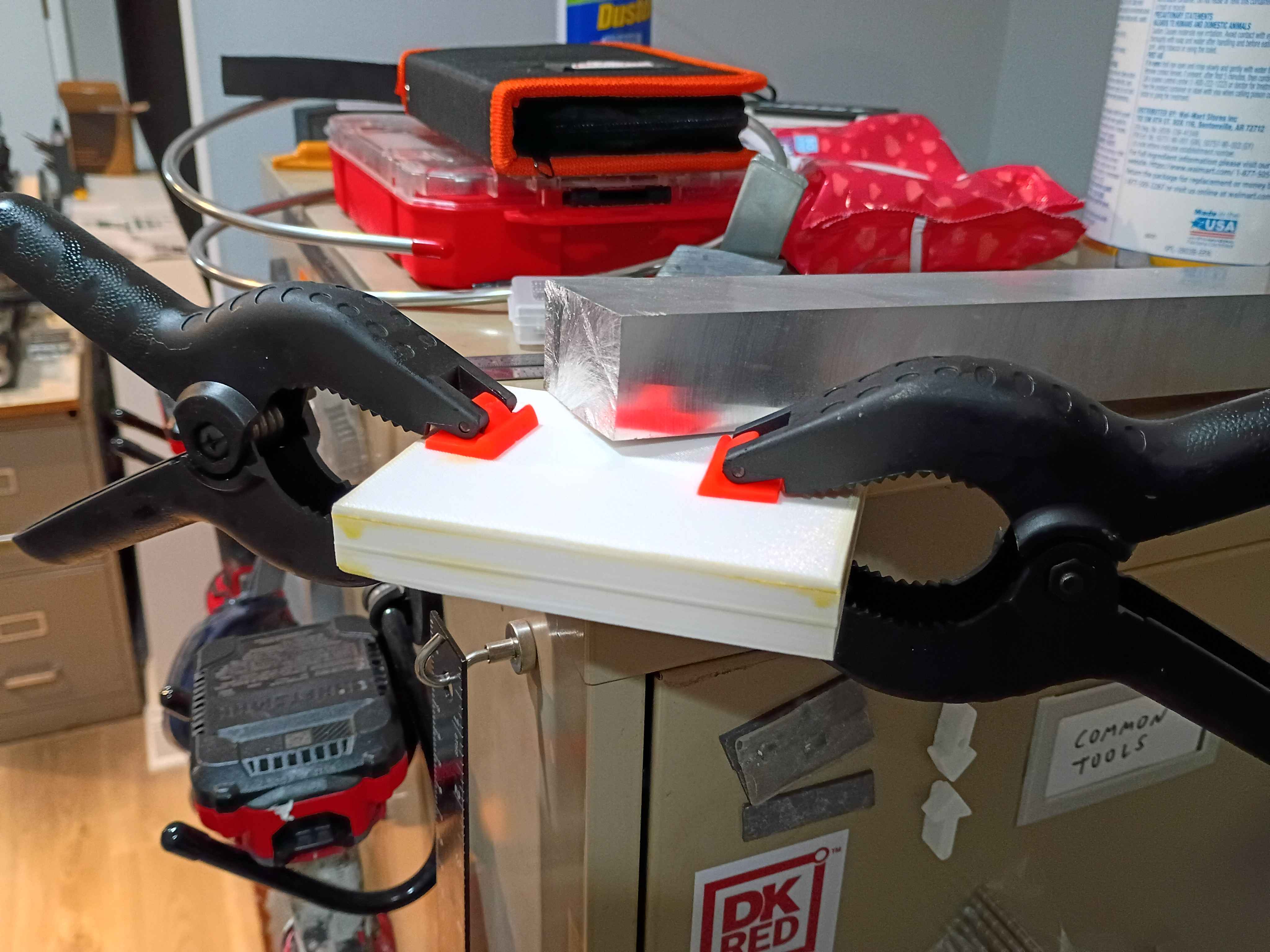
Attempted a silicone cast of the mini mat. Also had to reprint the primary clamshell mold piece due to having the text incorrectly mirrored on the first print. Due to the lack of air, I will give it 24 hours to cure and report back tomorrow. 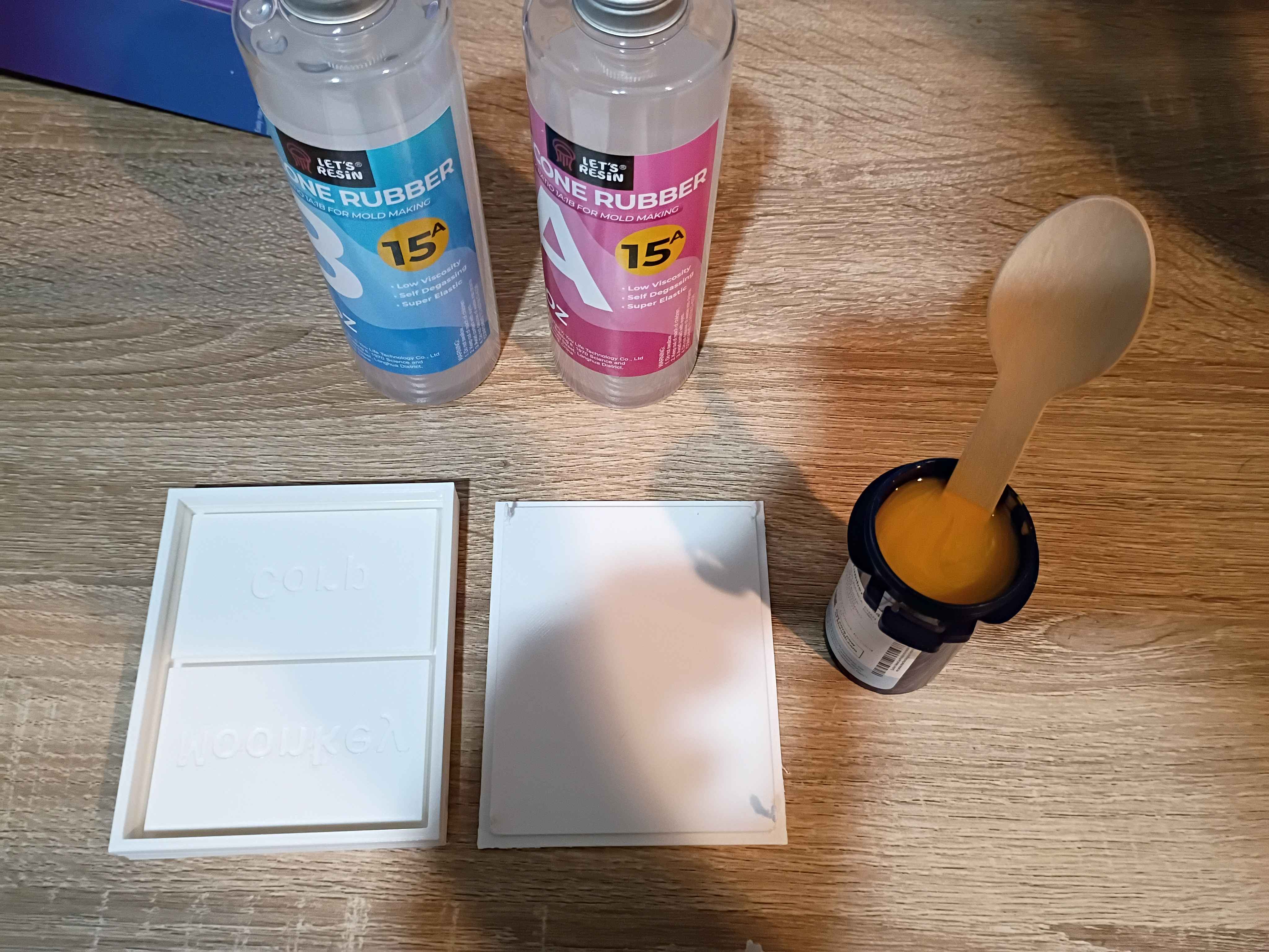
Added grant budget processing to Mary-Bot. All authorized organization members can submit a !grantrequest and check the !grantbalance, but only requests submitted/approved by Matt will be tabulated.
Designed and printed 2-part test mold for a silicone mat with slots for embedded magnets. This is ultimately for a potential client. 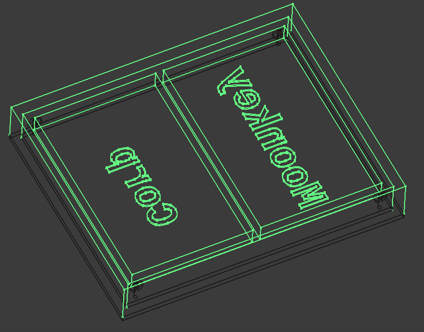
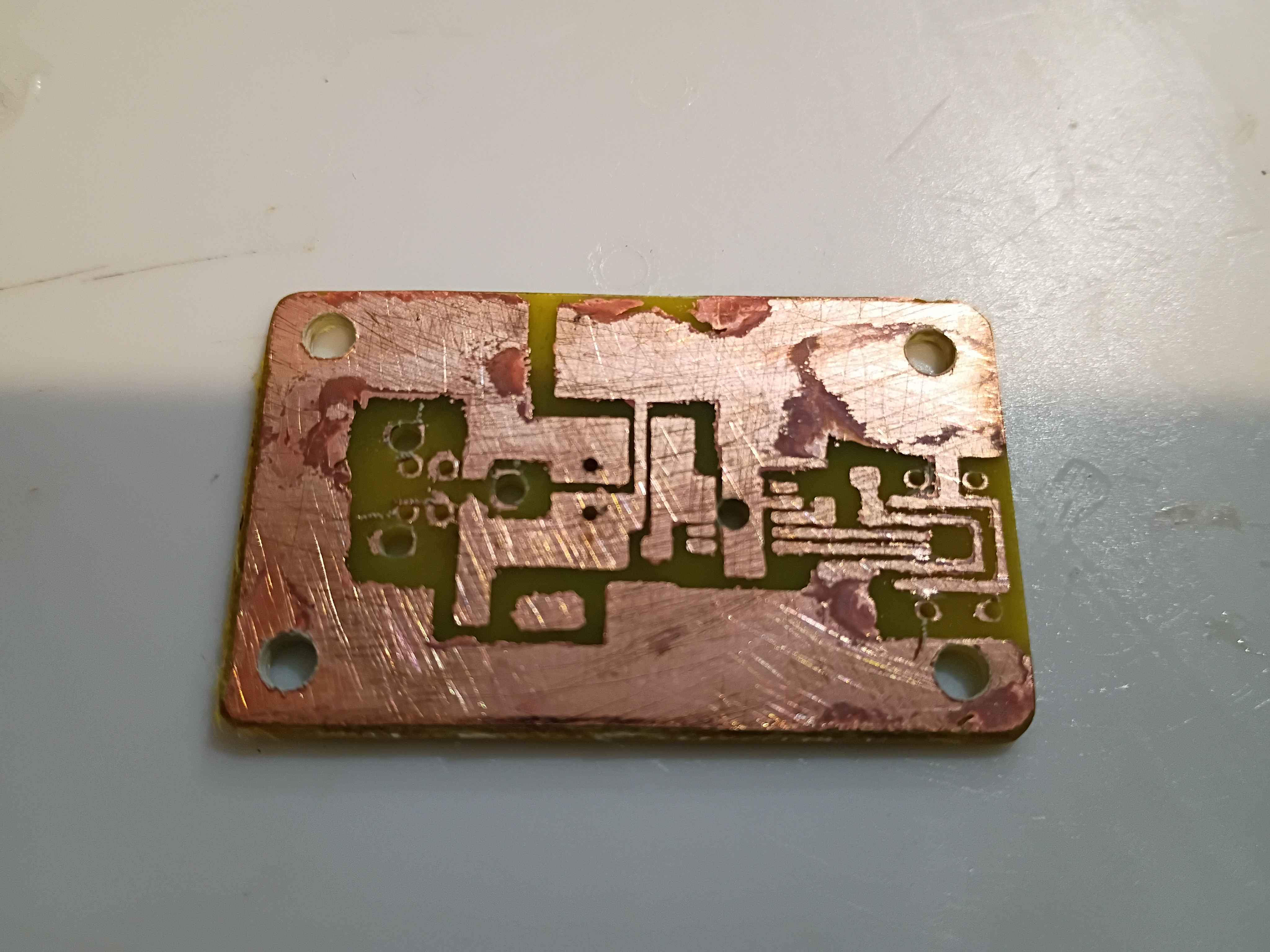
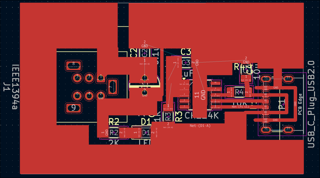
Shrunk the previously-validated 02004-004 PCB design by removing the hole pattern and adjusting the components slightly, creating the 02004-005 PCB shown below, which is 43x21.5mm. As a test of OSHPark's fulfillment speed, I ordered 3 of them (normally $7 for 3 with free shipping) with their Super Swift Service (half the processing time) and added $10 2-day Fedex shipping. It should also be noted that OSHPark lets you reupload and overwrite your designs (provided the new one is the same size) up until they are panelized. 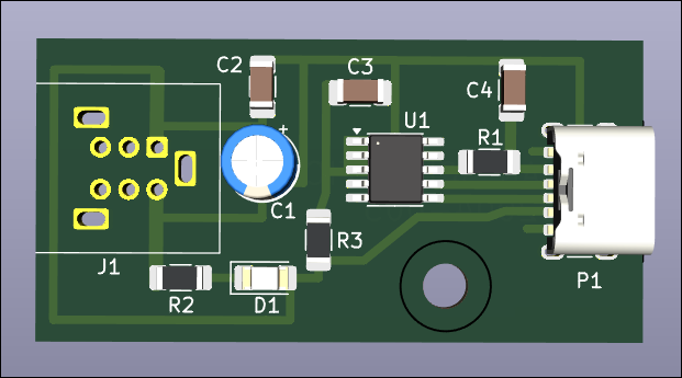
Etched the newer smaller 02004-004 trigger board. Designed and printed the 02004-004T1 drill guide to locate the mounting holes, and it worked absolutely perfectly. Popped the holes in and soldered the components. Put a few calculated drops of super glue to secure the connectors and successfully tested the circuit. Blue LED this time so I can save some green ones. Overall the fabrication went extremely well. 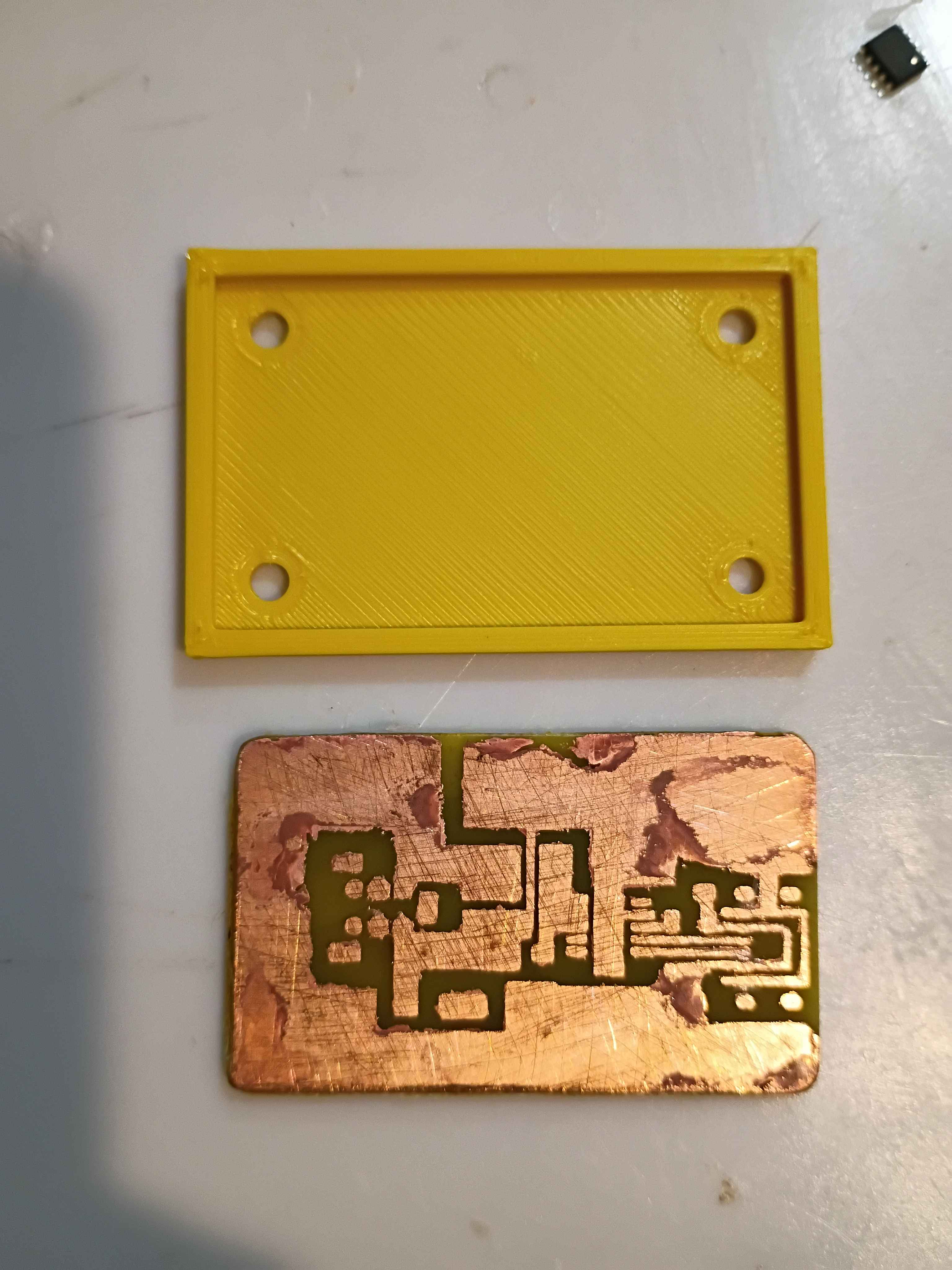
Repaired 1 of 2 additional evaluation units for the client and prepared them for shipment tomorrow. The other unit suffered too great of damage for repair, despite my best efforts. Developed a smaller and improved PCB design (02004-004) that removes the configuration resistor and jumper as well as increases the edge distance around the holes. This design is 8x7mm shorter and has several features for improved manufacturability. 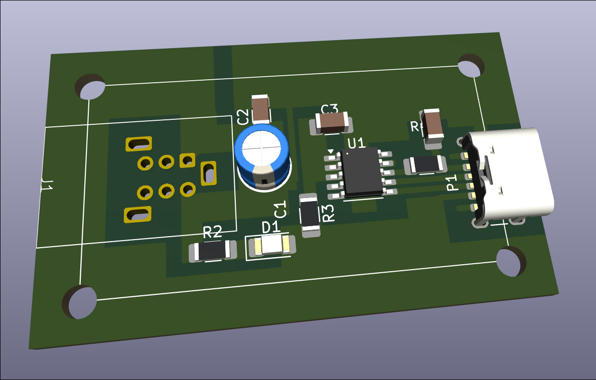
Notionally completed 2 more evaluation units, but determined after some testing that the USB-C connections are not adequate and need to be redone. Input provided to designer for future units but the current fabrication effort will require a clever approach. 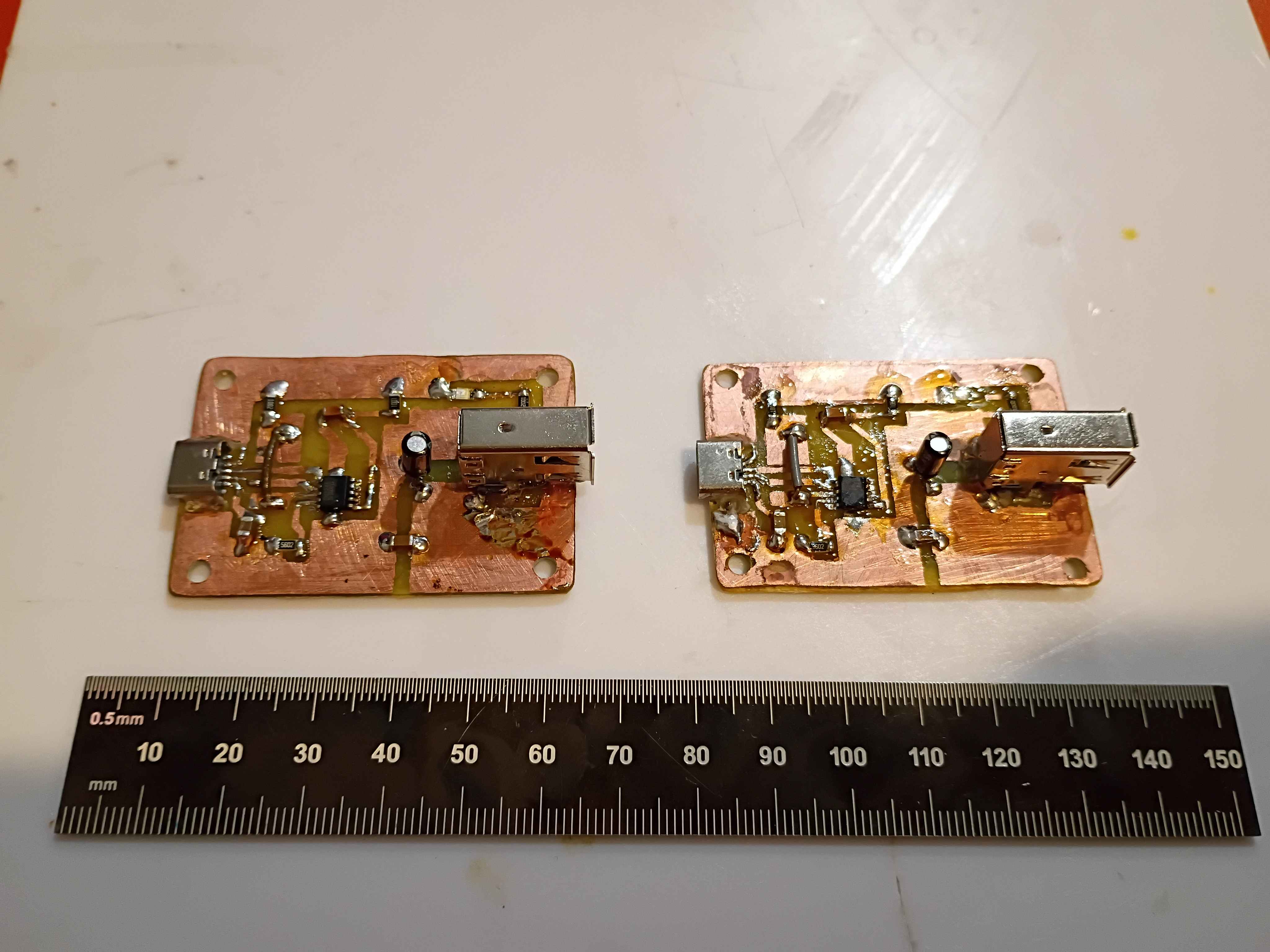
Began fabrication of 2 additional evaluation units for the client. Boards etched and drilled, and box assembly components printed, though one part requires reprinting due to some damage incurred during a prior attempted repair with a heat gun. 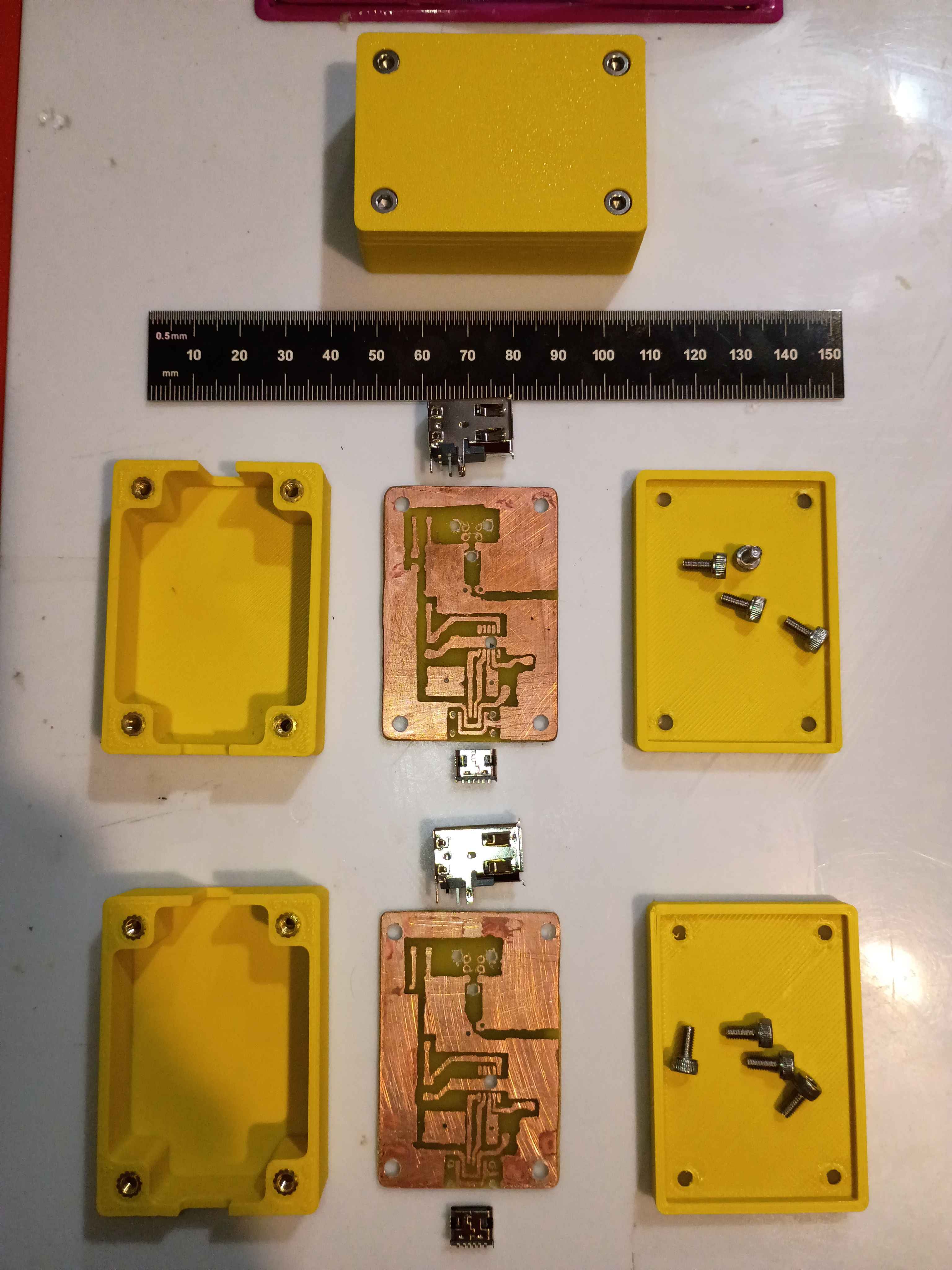
Today I updated the 02004-001 PCB.
Last week I made a parts List that's necessary for the manufacture of the 02004.
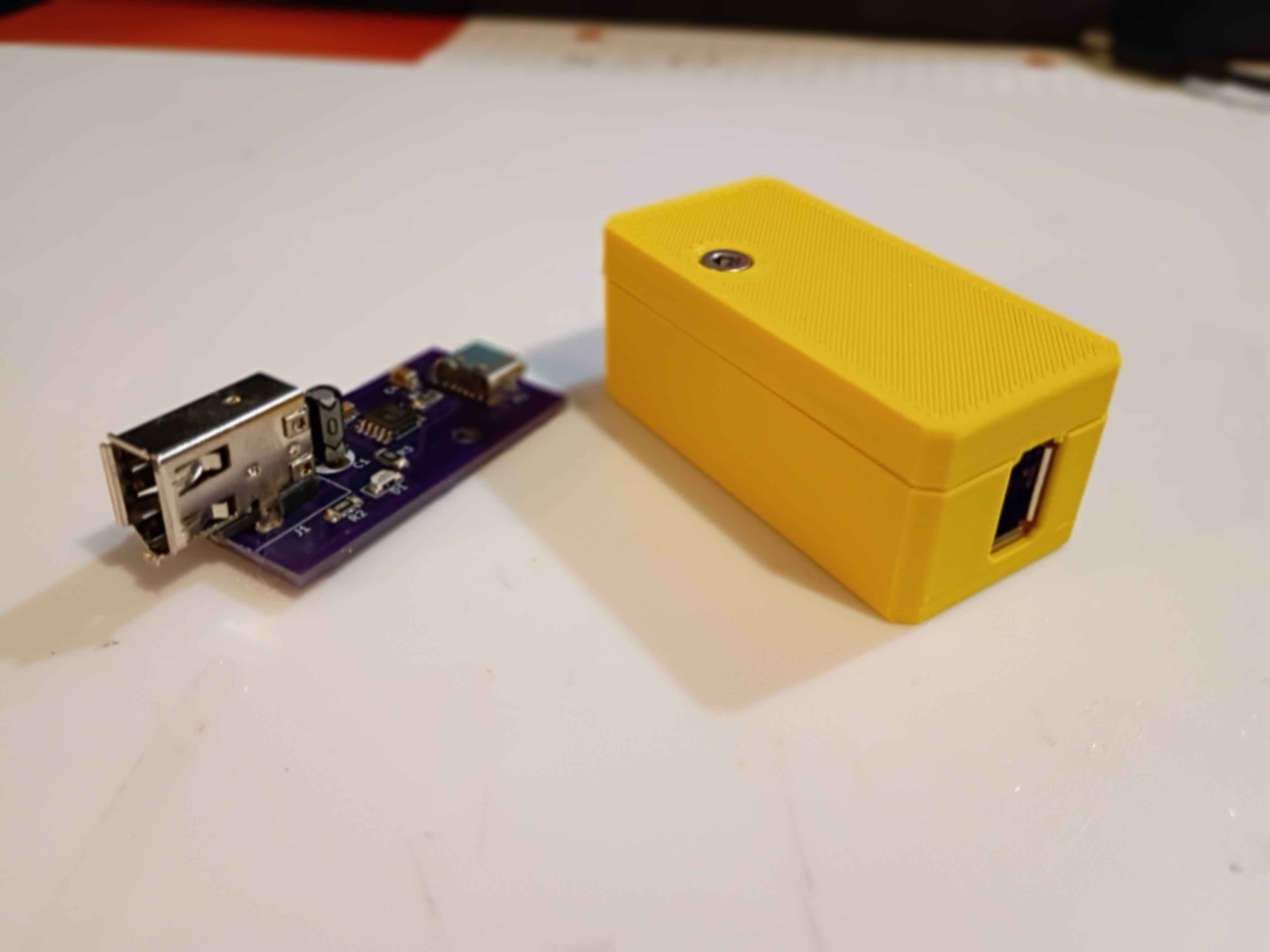
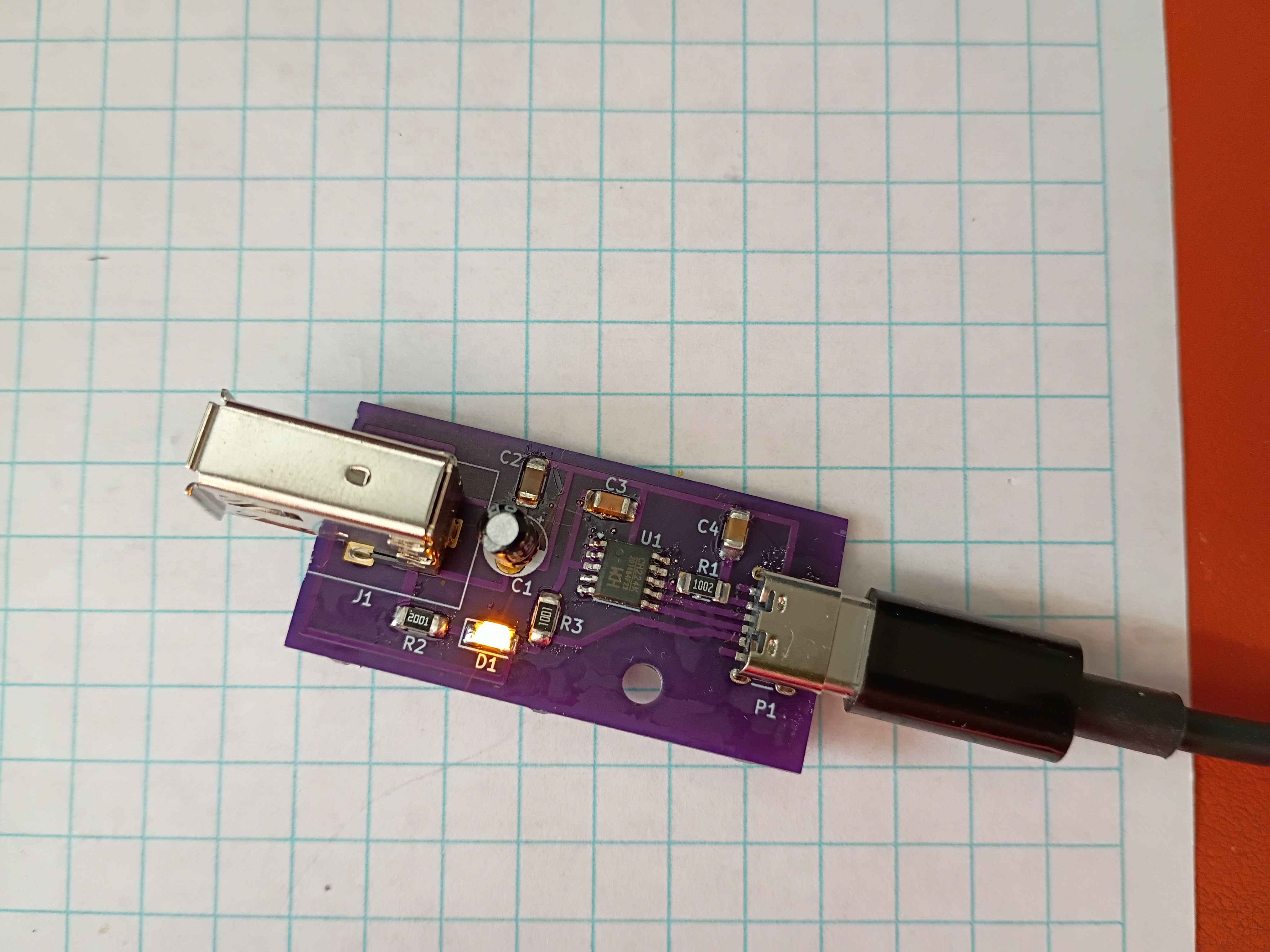
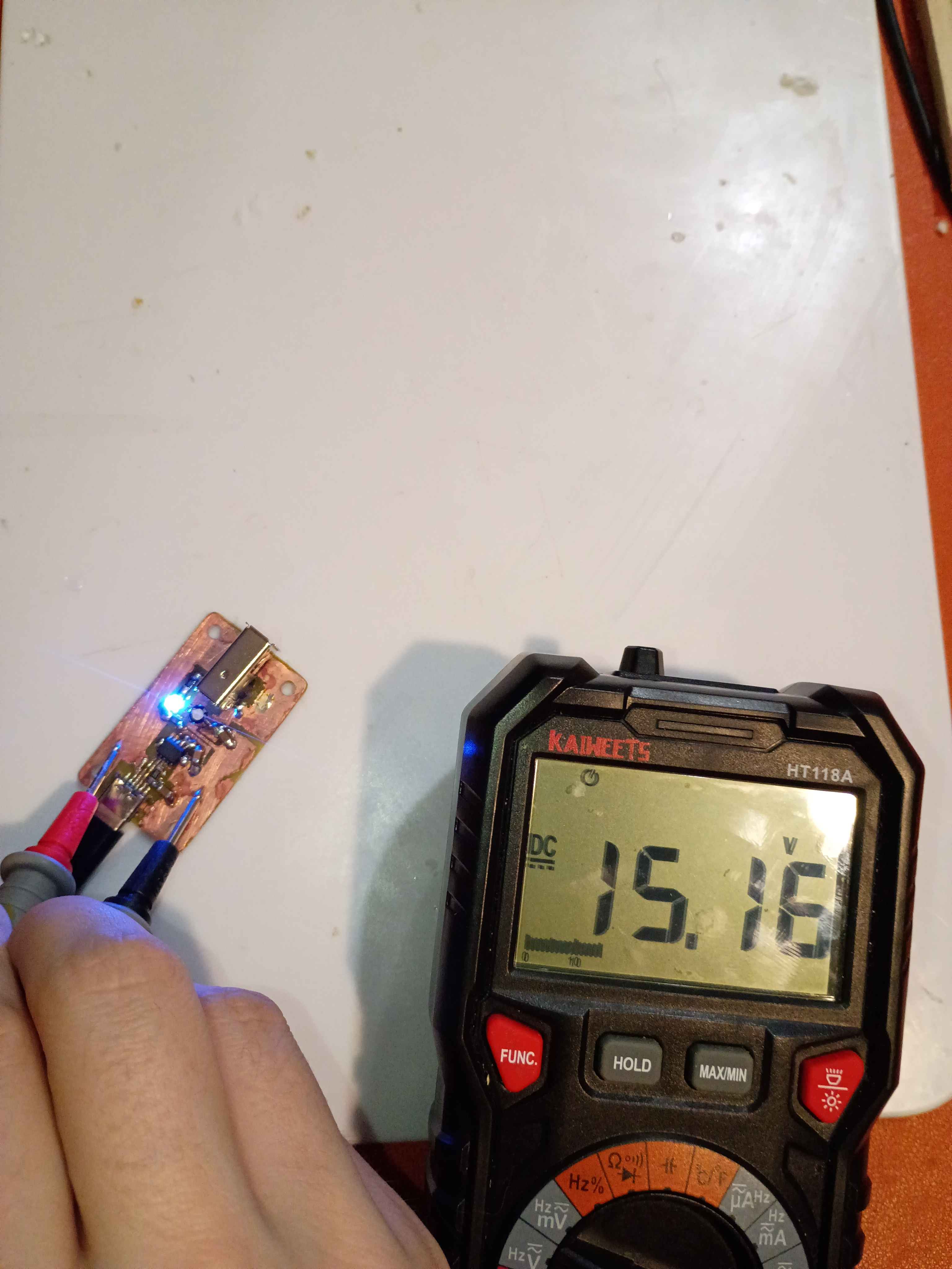
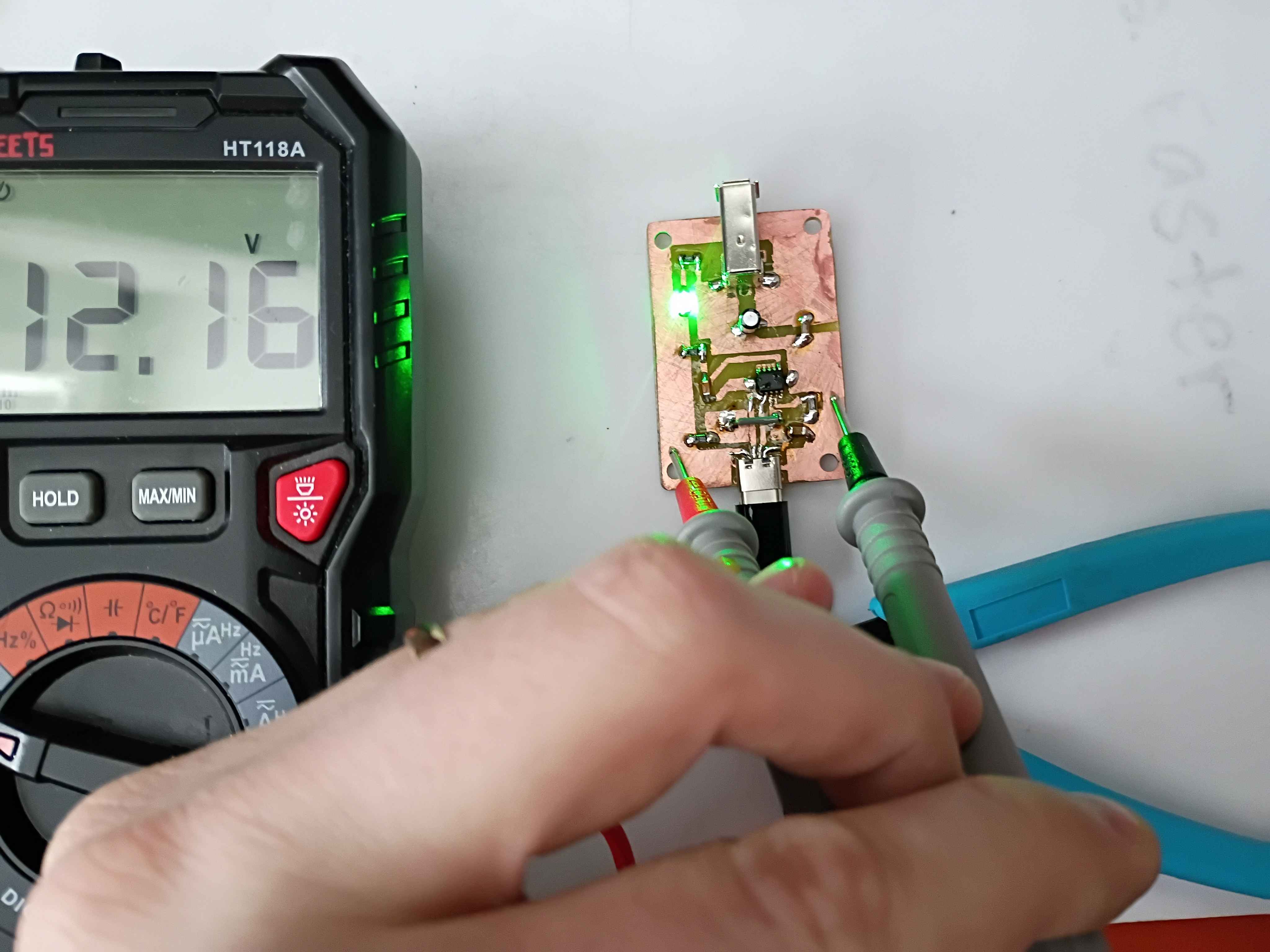
The circuit does seem to work with a 65W USB-C-PD charger, outputting the correct 15V. However, after repeated use, the USB-C port came a bit loose on the circuit and eventually detached. I resoldered it and applied even more super glue to secure it in place. I began reprinting the second case, this time letting the plate cool completely before popping off the print, in an attempt to remove the white haze from the bottom surface. 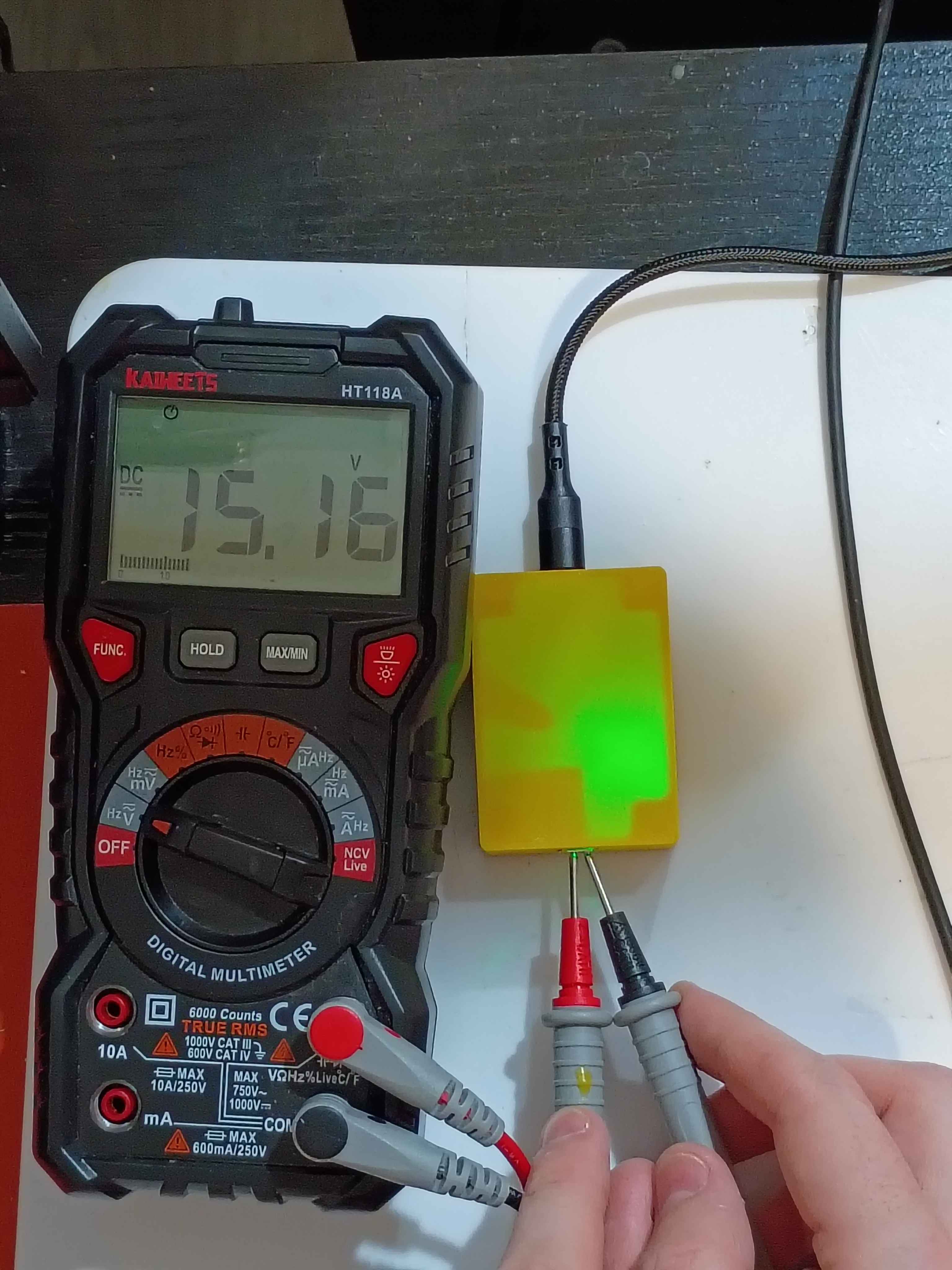
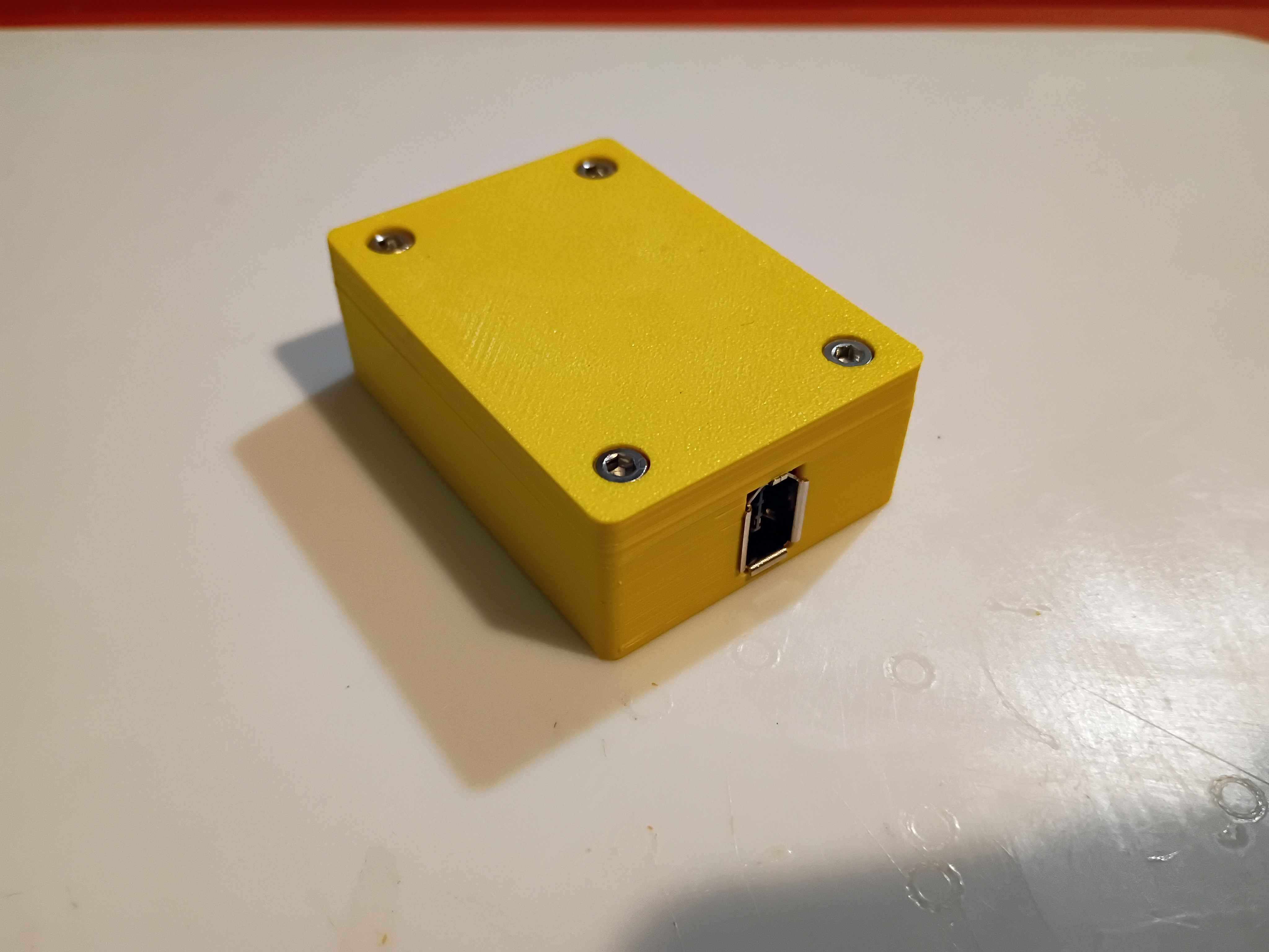
Printed revised box assembly out of ASA and assembled everything together. Had to tune the new printer for this filament for the first time. 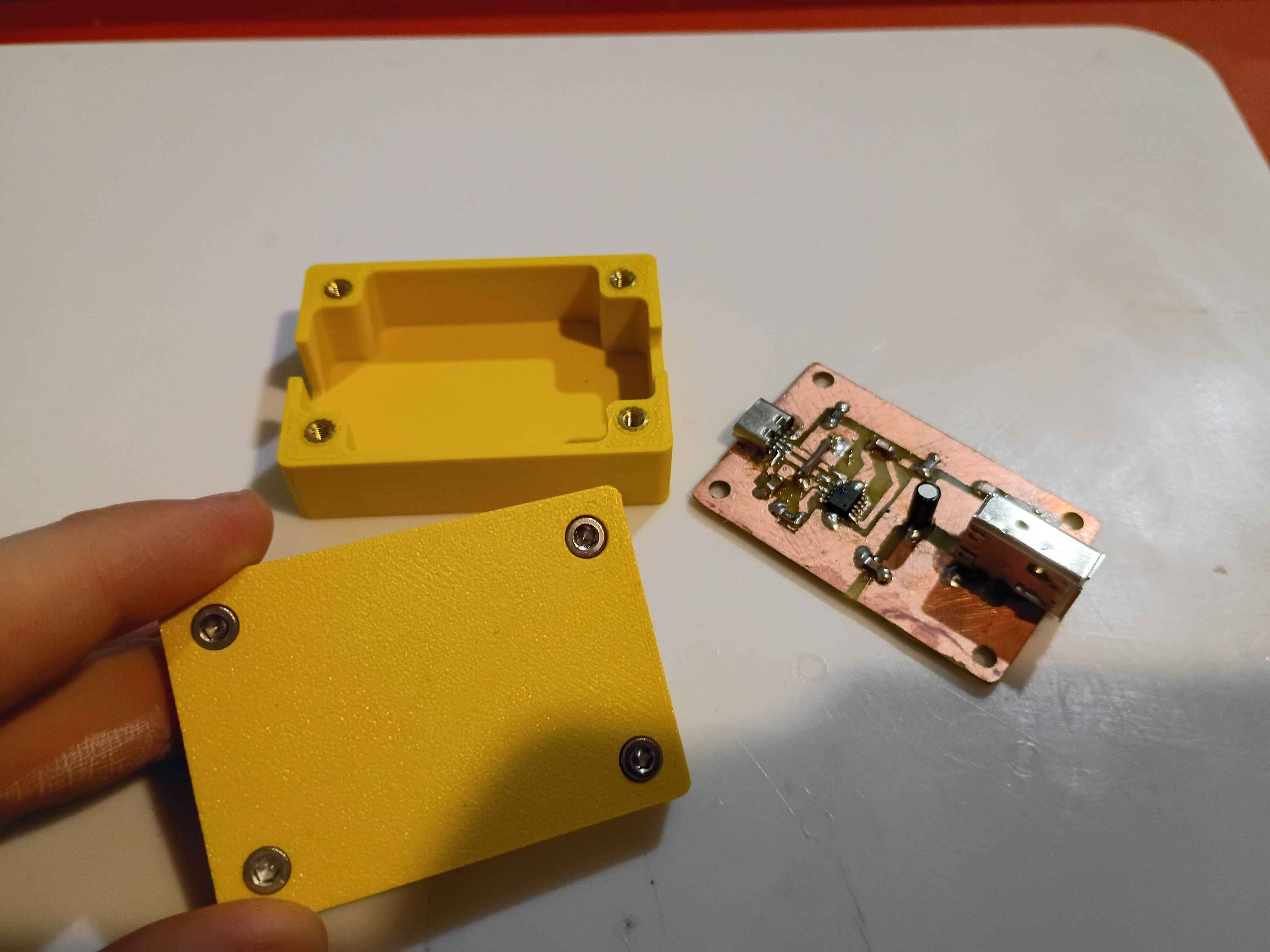
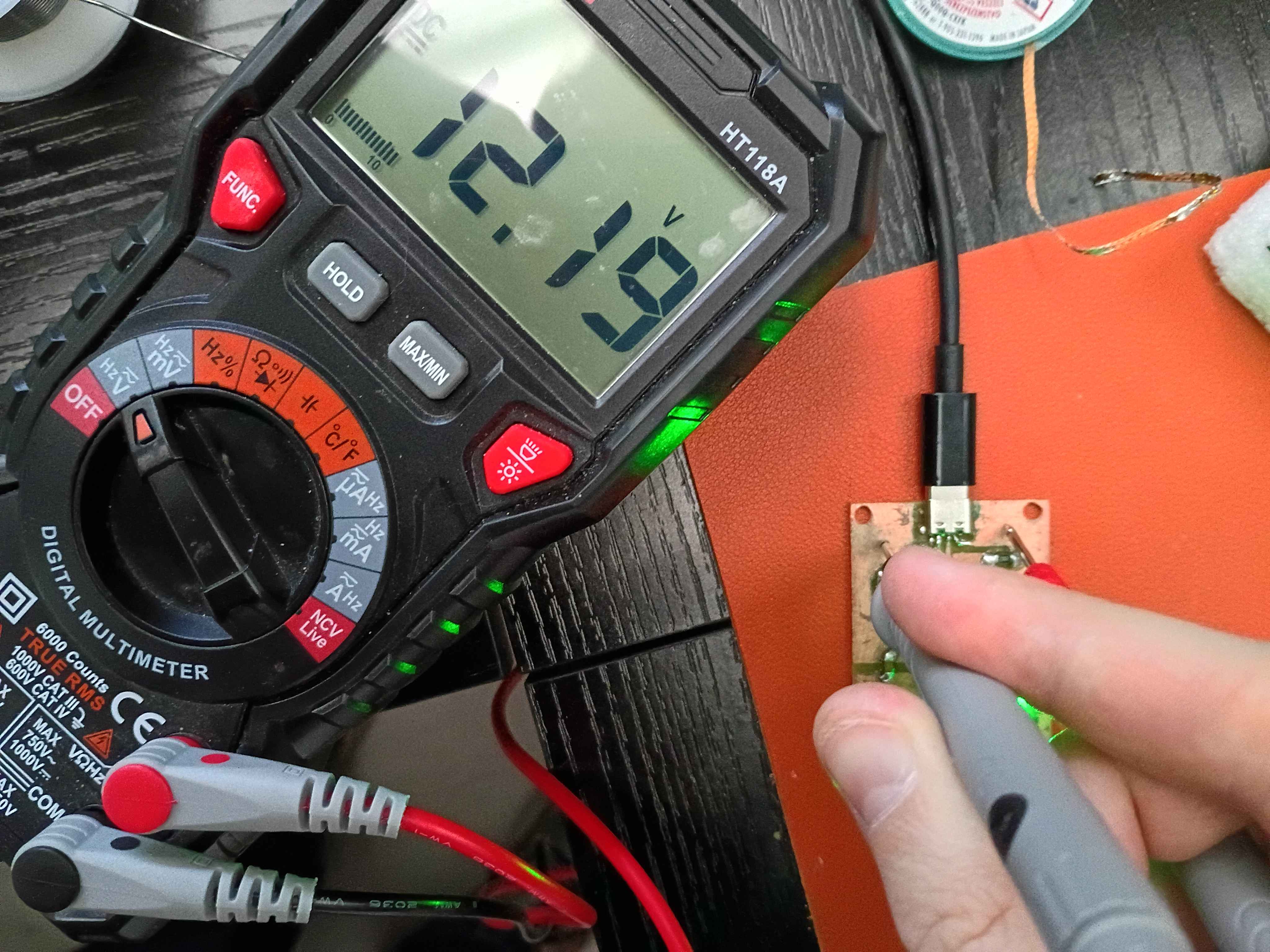
Completed second iteration of the prototype circuit board. It took 2.5 hours from printing the mask to testing the device. For future reference, I did immediately quench the board after toner transfer, so that didn't seem to make a difference. Still only get 12V max output, hopefully tomorrow I will receive a PD charger and cable capable of 15V. 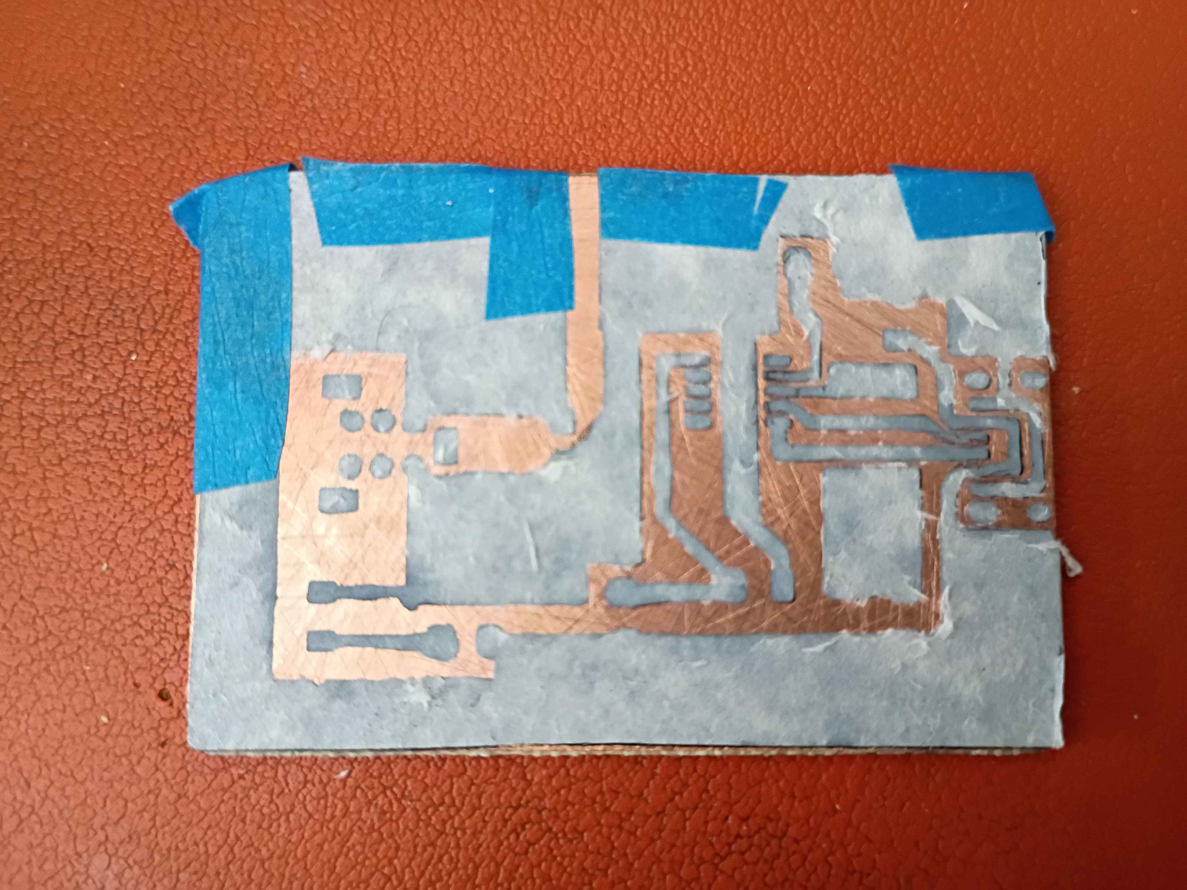
Received FireWire sockets and trigger IC and tried several iterations to get everything working. Eventually the circuit essentially works, though for whatever reason I was only able to negotiate 5, 9, and 12V. 15 and 20V did not work. I am sourcing different cables and chargers to see if that might have been the problem. Consulted on PCB design revisions for manufacturing considerations. 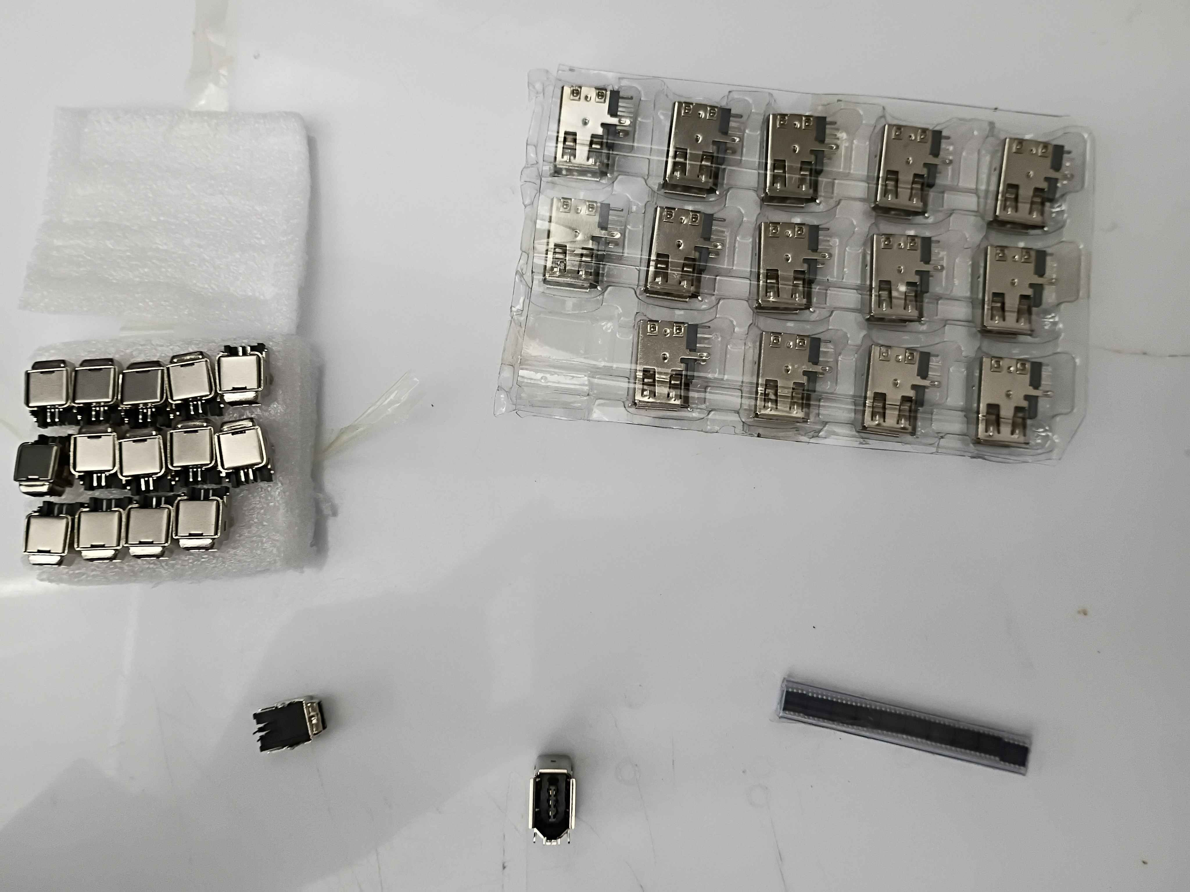
Painstakingly filed the circuit board to size to fit into the box assembly. I really need to stop being so 'conservative' on the board snapping. Or just put a lot of extra clearance in these boxes. 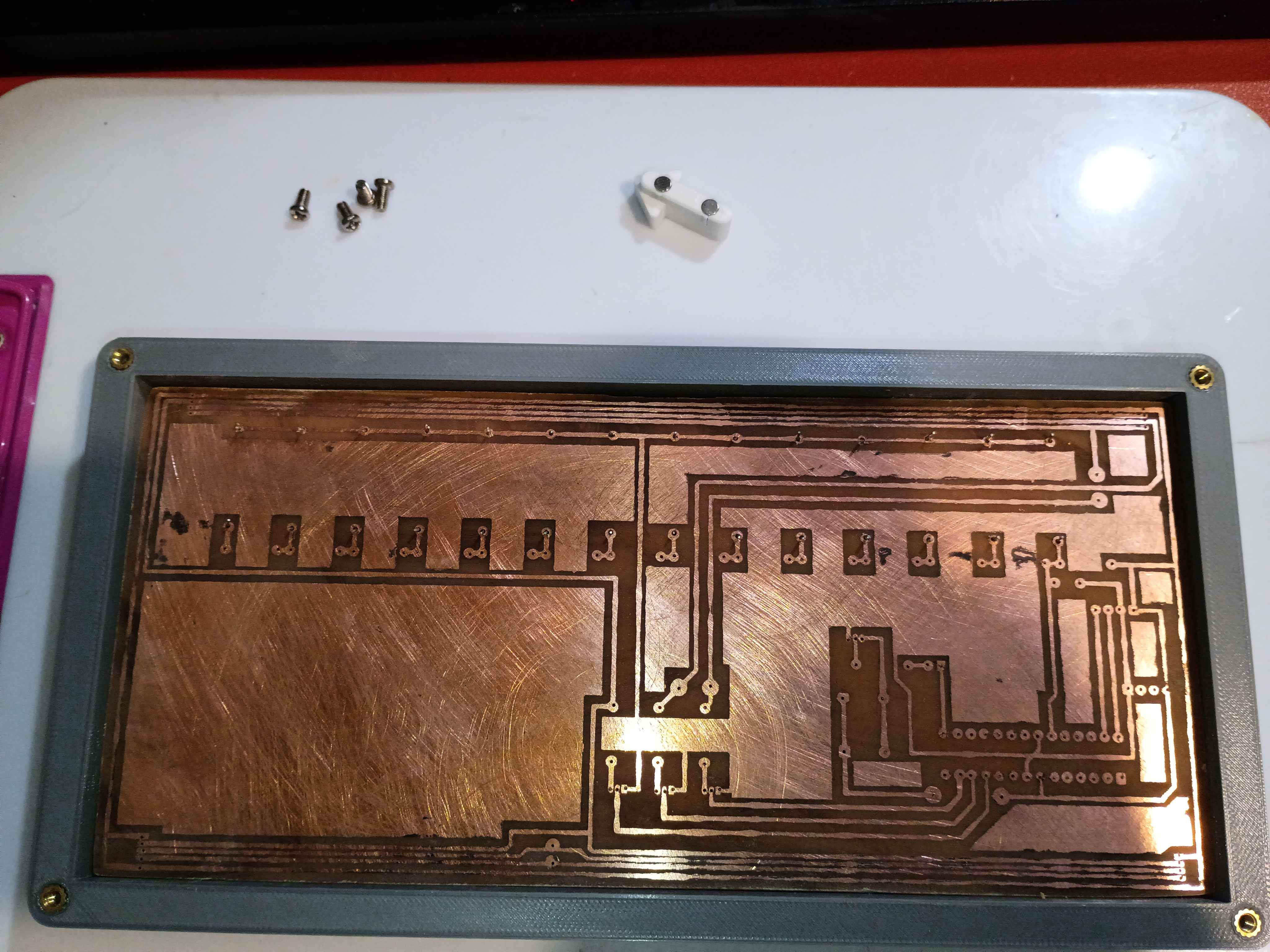
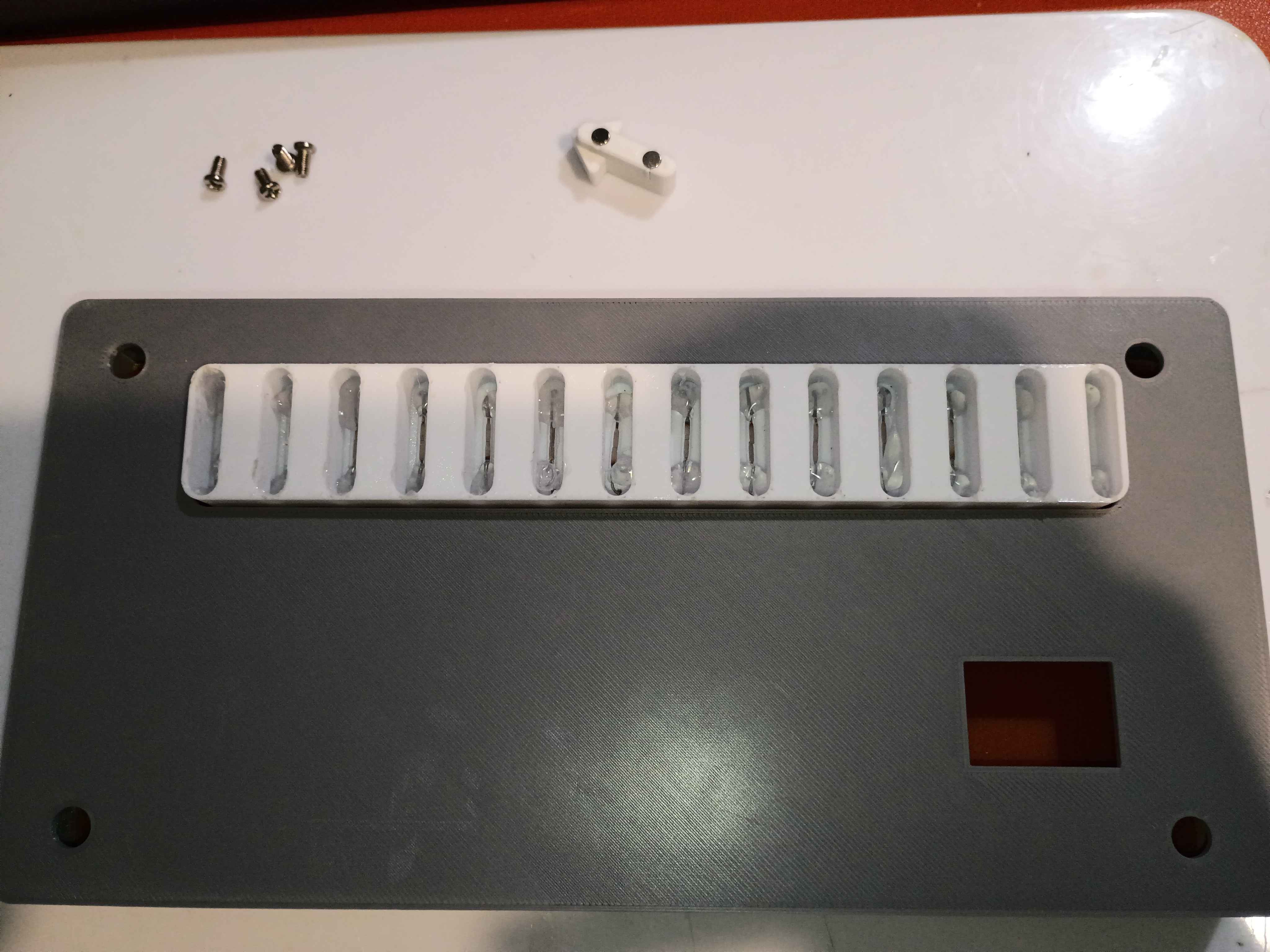
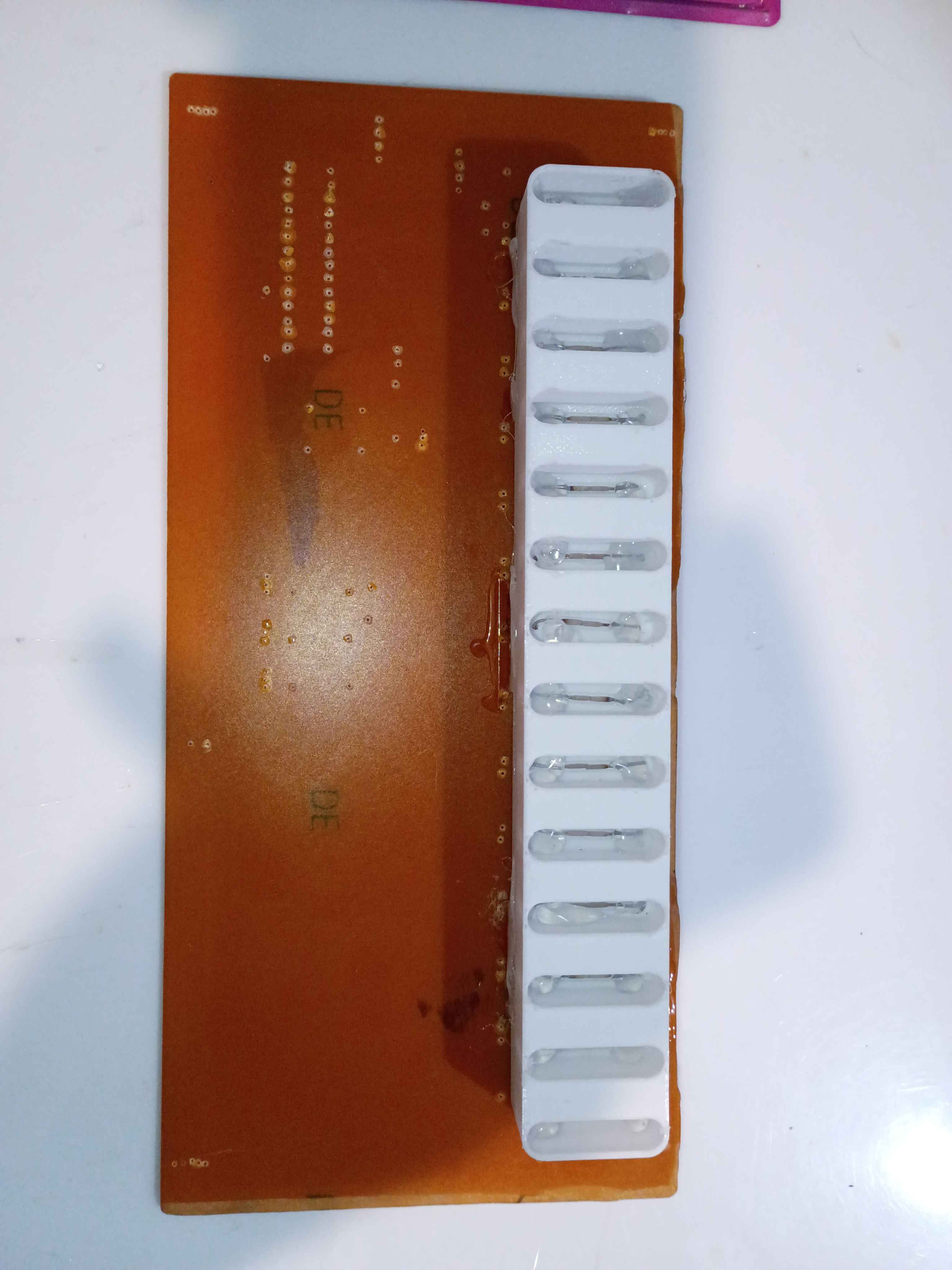
Reprinted slotted component with deeper slots. Bent and installed reed switches, put a dab of glue on each lead to keep them in place, and then installed the entire slot assembly onto the PCB. After testing with the magnetic input device, the slots are the perfect depth to prevent all false positive readings. 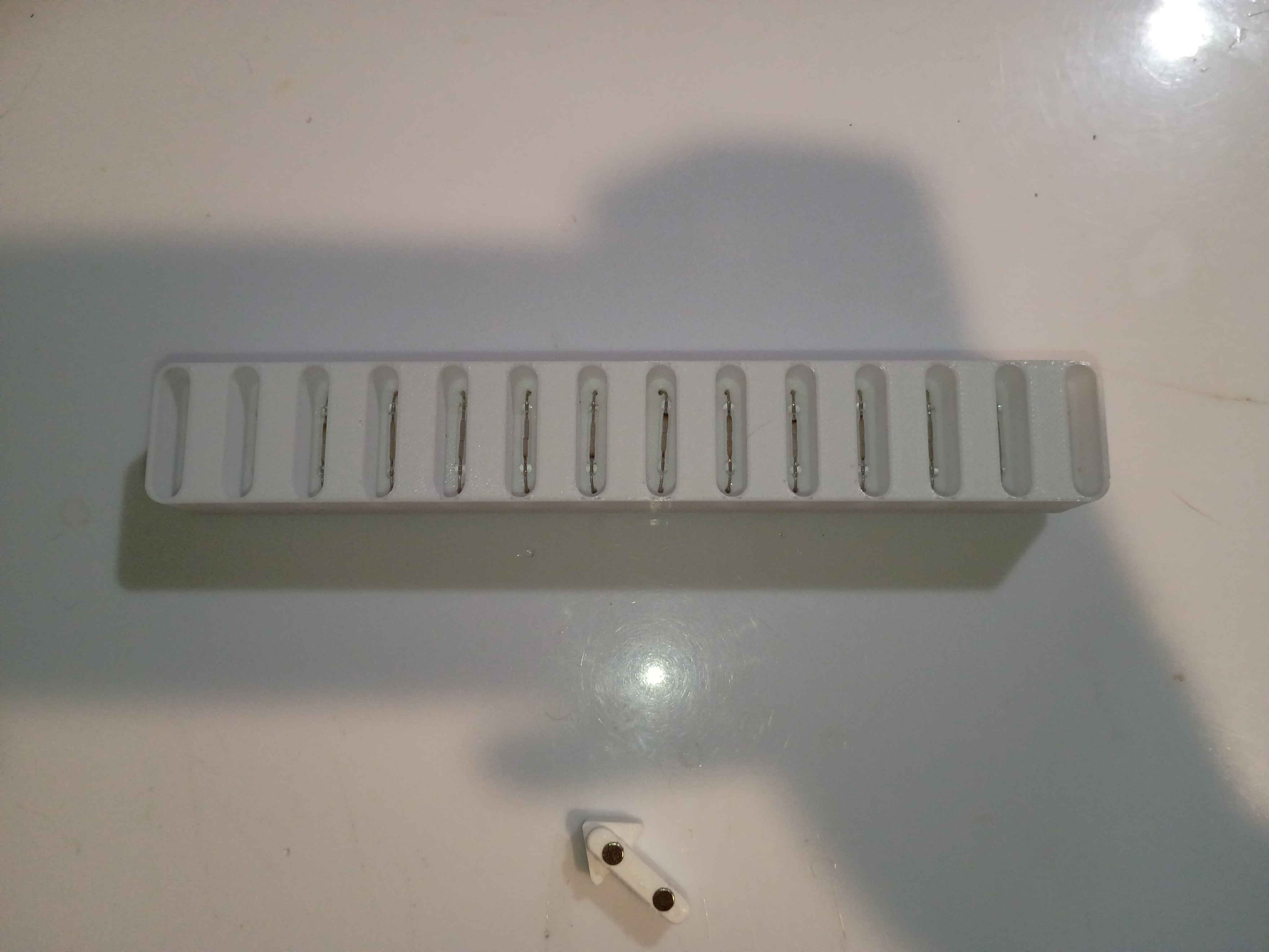
Tested enough configurations of the reed switch to understand the ideal part orientation. Ideally two opposite magnets should be oriented into the ends of the glass tube, perpendicularly, and the flat faces of the reeds should also be facing the magnets. Updated the 03010-006 input device to handle this new spacing and printed for a successful test. Also because this configuration is so sensitive, to prevent false positives, I updated the 03010-003 input slot component to recess the reed switches 5mm lower down. That updated CAD file is uploaded for printing tomorrow.
Received capacitors in mail. Drilled holes in circuit board and soldered caps and LED. Confirmed the LED is mounted correctly. Now we are just waiting for the IC and FireWire socket to be delivered. 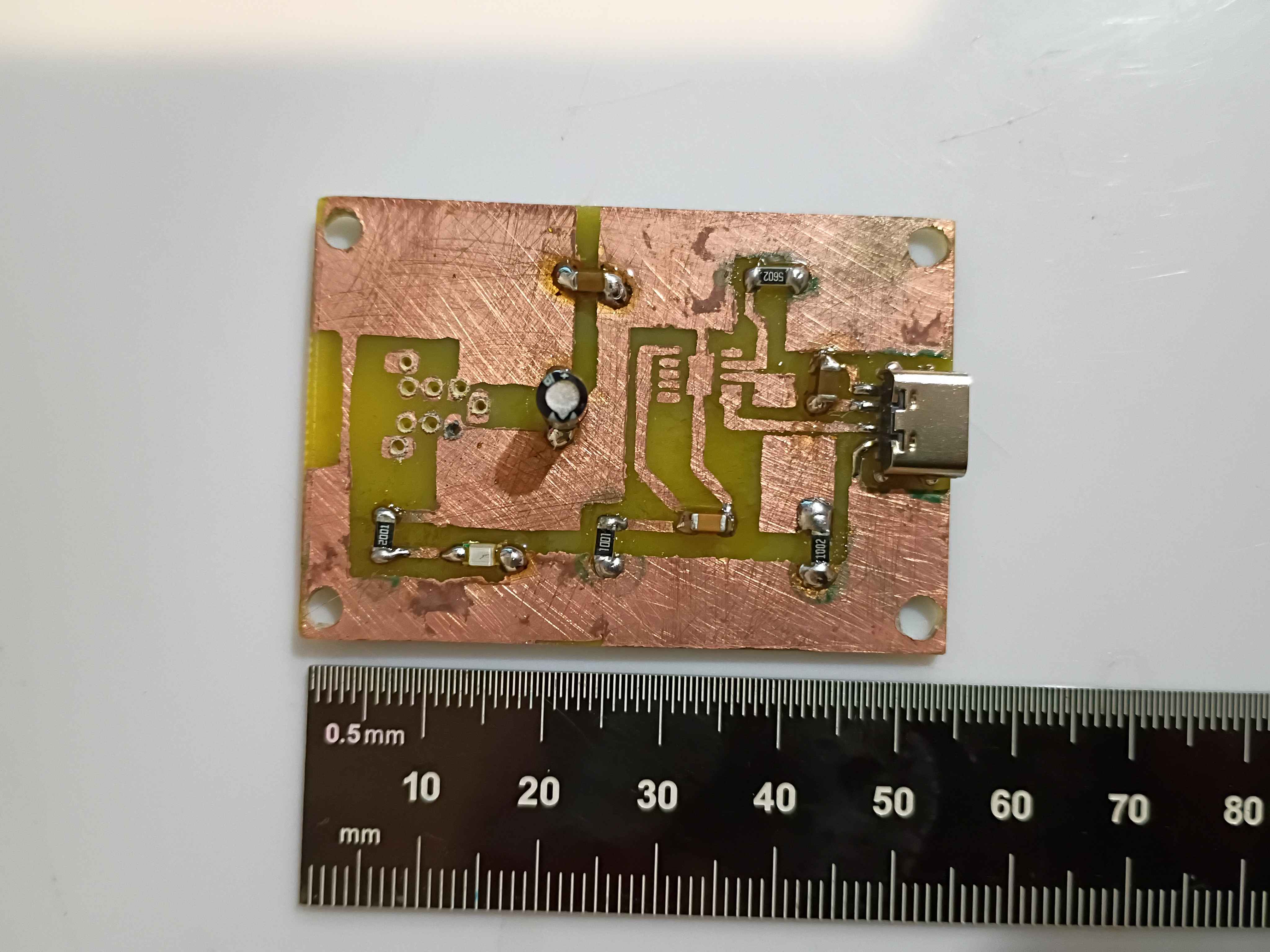
Reprinted box components and reinstalled heat set inserts. Drilled 0.6mm holes in etched PCB. Tested some configurations for the reed switches. 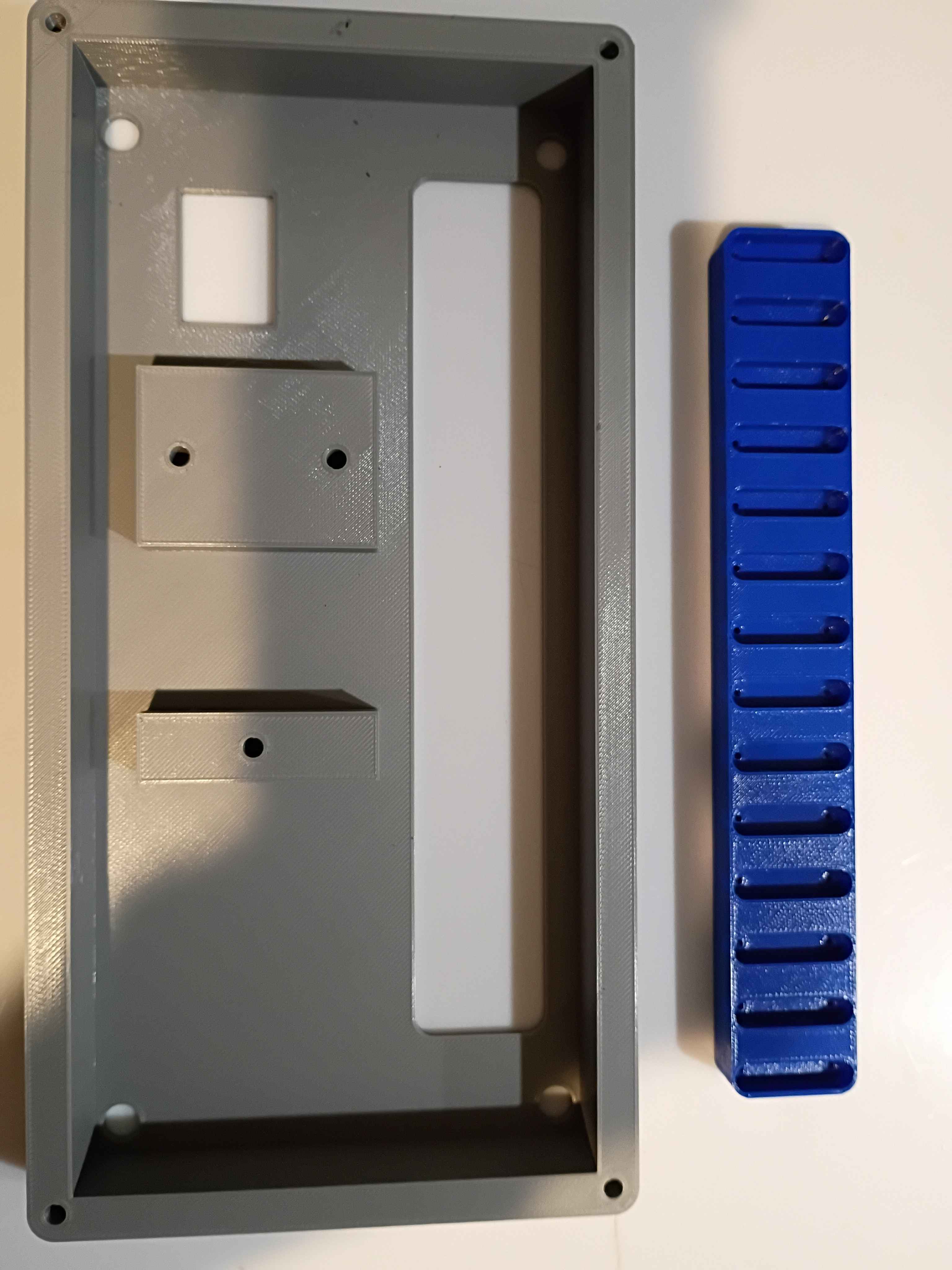
Added feature to Mary-Bot that shows you a rendered preview of your article as soon as you post it. No need to wait for a full website regeneration. Also, the !regeneratewebsite is now faster because it doesn't recreate every single image thumbnail, only the text. There is a new command: !fullregeneratewebsite, which is basically the old !regeneratewebsite. I also added a slight amount of security to the !deletejournal command, to prevent slip-ups.
Updated .3mf files in GitHub repo for printing at work tomorrow on the large format printers. Updated and printed the input device to accept an 1/8-inch dowel for a handle, among other slight adjustments. 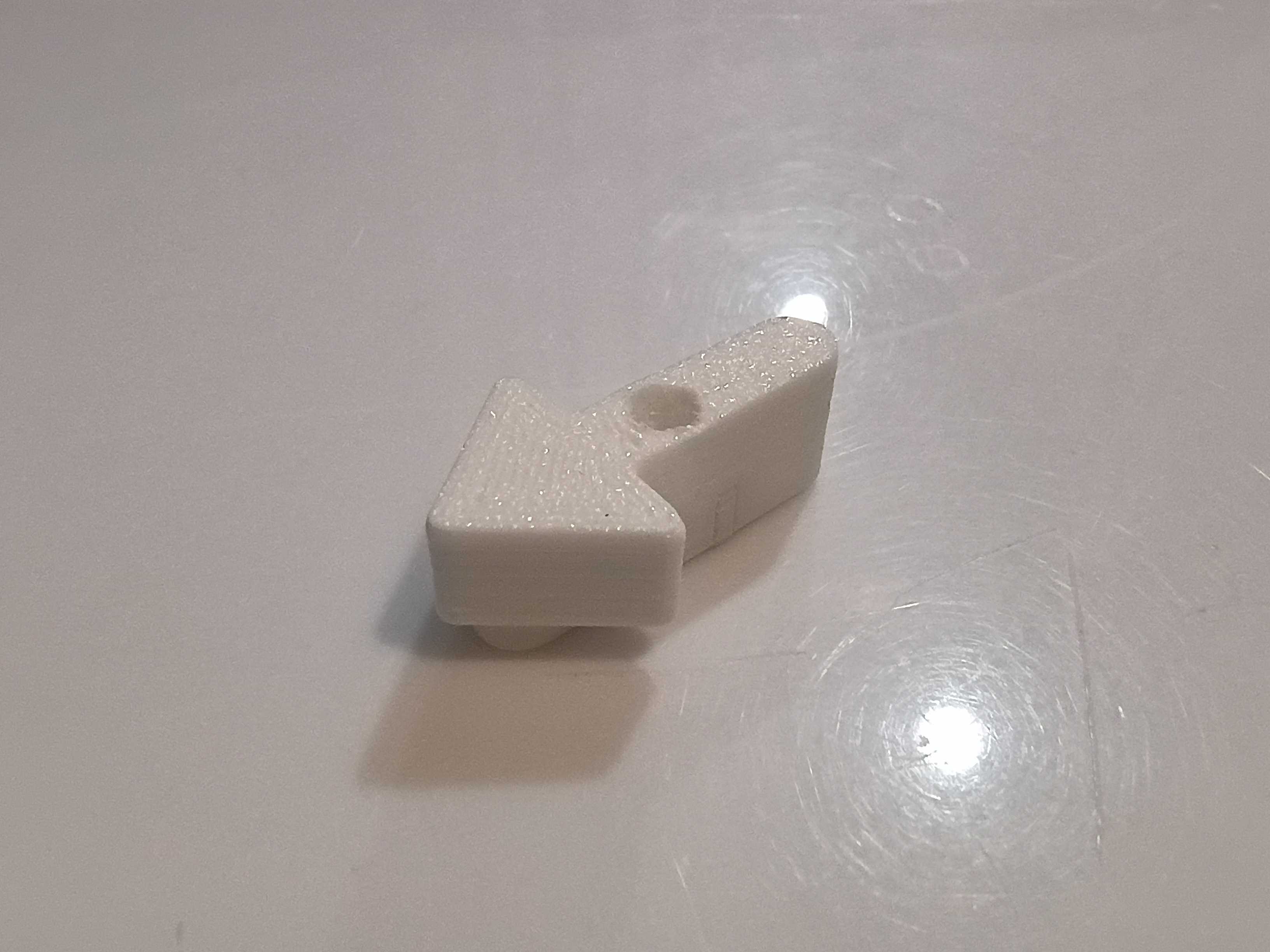
Filed off burrs and soldered components to one of the stepper motor driver PCBs. I oriented the screw terminals in a consistent way for easy wire installation, but that does technically deviate from the schematic.