Began teardown of TL902 thermal laminator for thickness mod and temperature mod. Located potentiometer and JST connector for temperature mod, and began redesign and print of one side of the internal bracket that spaces the rollers apart.
Finished automated graphic rendering for the pentecost-pursuits status and implemented the submission process, requiring a journal entry. Type !help in that channel to see a description of the commands. 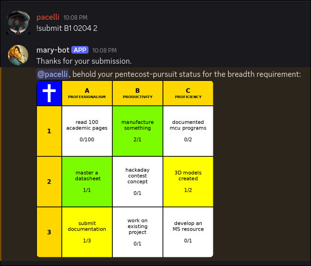
Added functionality to Mary-Bot to not require IMG tags in journal submissions, fix a bug regarding the termination-notice filetype, and did some preliminary work on the pentecost-pursuit graphical rendering backend. 
Did manage to get a toolchain working for the plotter using jscut.org. Originally I attempted to use InkScape's built-in Gcode plugin but was unable to operate on the circuit mask because there were too many paths. Eventually I figured out that you can ungroup, flatten and then reconstitute all of the features into a single path, though the order to do that requires some stumbling around. By that point, I was using jscut, an outdated browser utility, which worked decently enough. The main problem was that because I didn't have the proper hardware to assemble the plotter head, the Ultra Fine Point Sharpie was rigidly mounted to the toolhead, making it blunt rather quickly, which caused both attempts at tracing the circuit to be unusable. At some point I will retry this with a different mechanical setup because the difficult part, getting the software to work, is behind me. 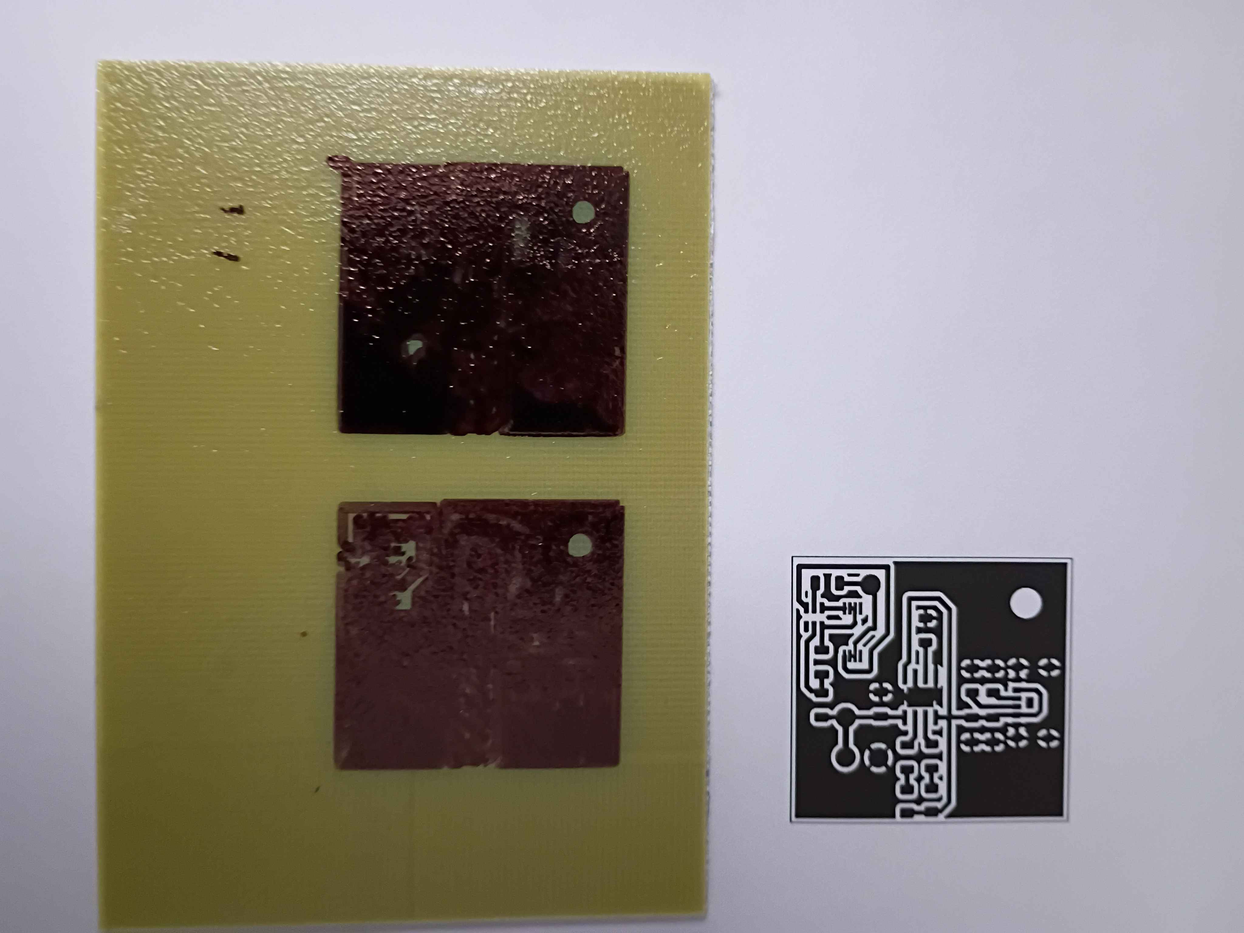
Added a basic employee tracking backend to Mary-Bot, also enabling her to terminate employees and issue a formal termination letter PDF with key details. This will eventually be extended further.
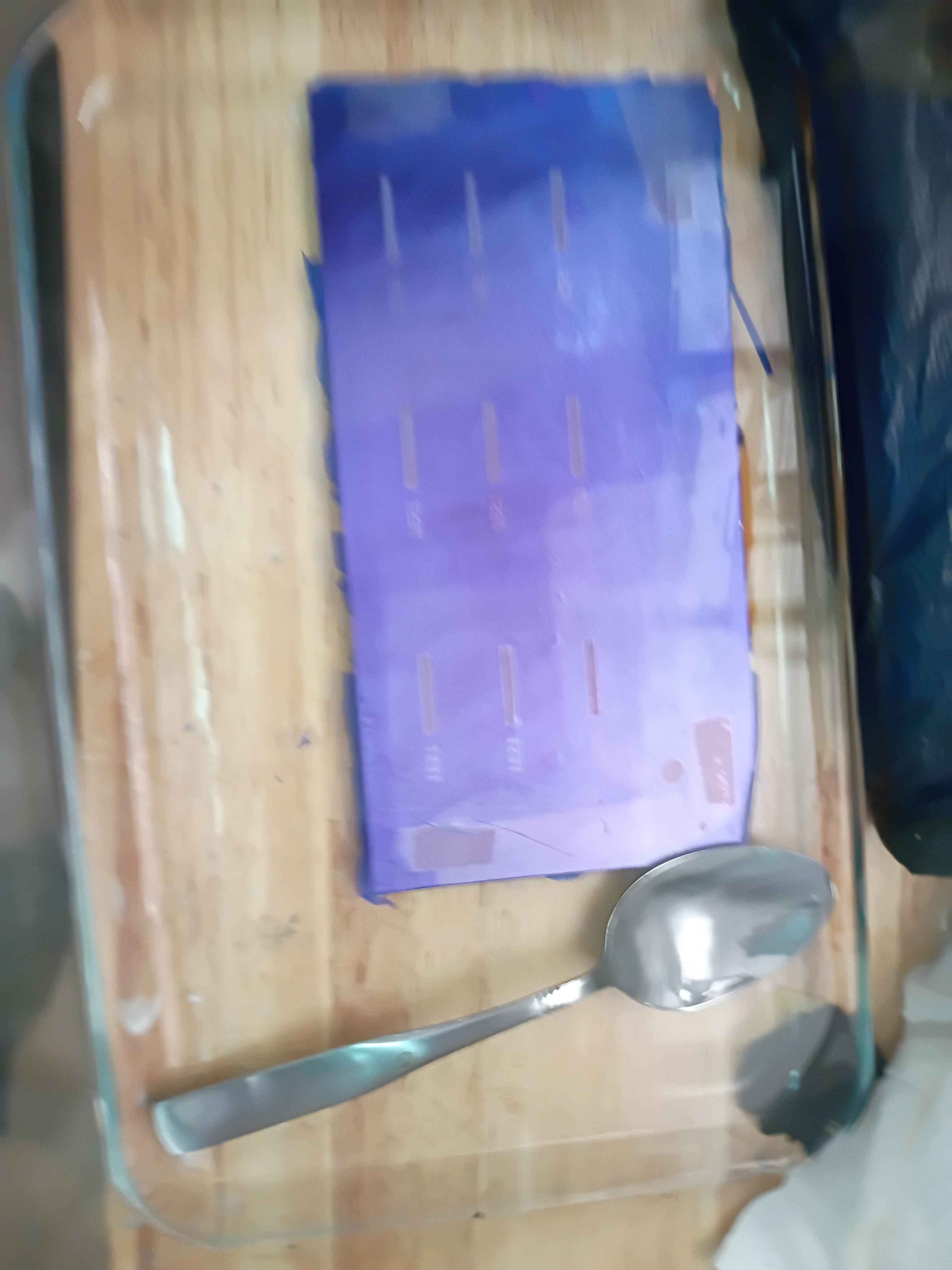
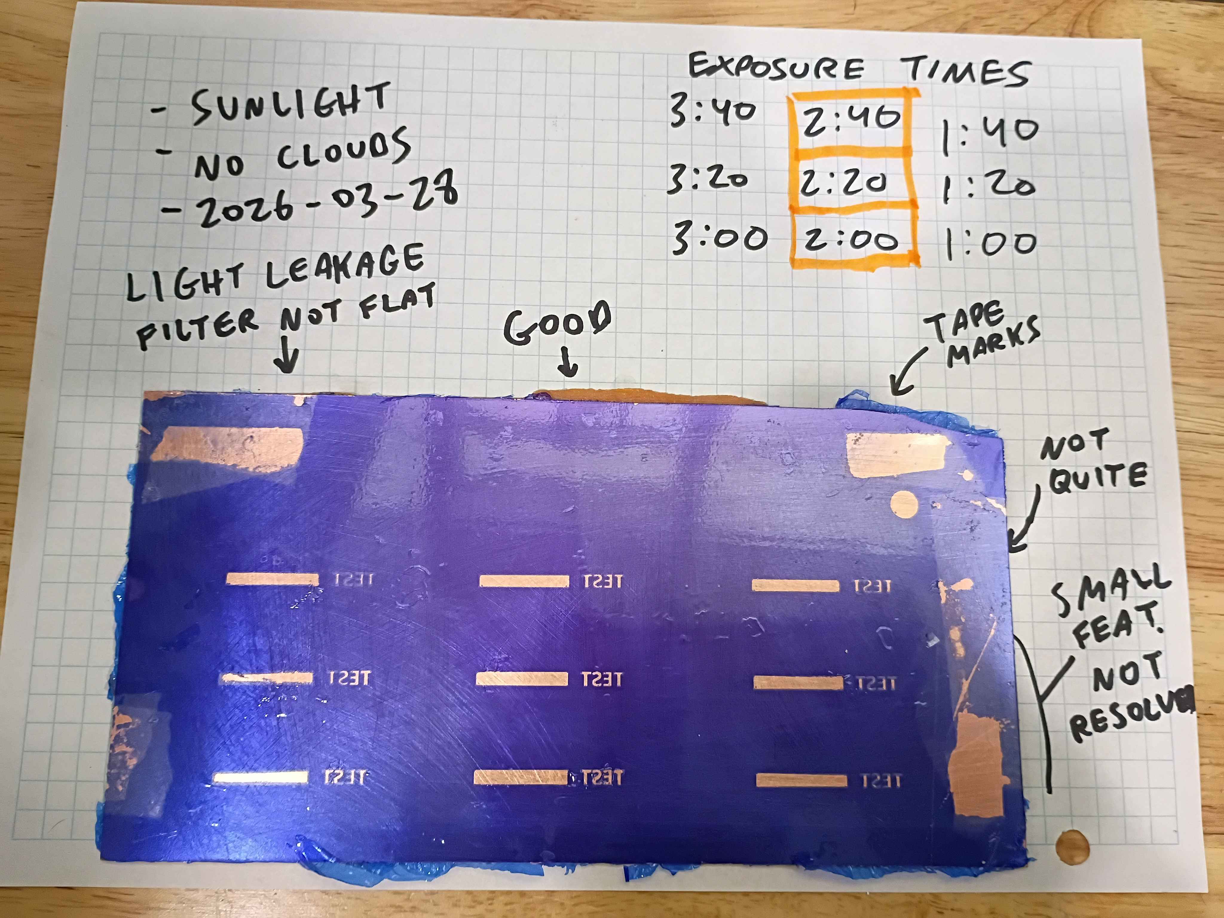
Re-attempted the use of dry film photoresist for mask transfer onto copper clad boards. Board was scuffed with 500 grit and then cleaned with acetone and IPA (actually I messed up the first film transfer and removed the failed attempt with acetone and wiped clean with IPA). The film was affixed mostly mechanically, with bubbles being removed by sliding them out by finger pressure. Limited heat was used, iron on low seemed not to help very much, though research suggests it helps the bond. A double layer of a light filter laser-printed on transparency sheets was taped to the surface and regions were exposed to the sun on this cloudless day in Bridgeport, CT (2026-03-28) for between 1:00 and 3:40 minutes. The filters were held flat to the surface by a thin acrylic sheet. After developing in 1L tap water with 1 tbsp dissolved washing soda for several minutes, the board was wiped dry. All the exposures >1 minute appear passable, though because the light filters were not pressed flat the entire time, the longer exposure times seem to have experienced some light leakage, though that could likely be avoided with a better clamping setup. Qualitatively the 2:20 exposure time looks best, with the 0.4mm features in the text being well defined. This is more than enough fidelity for most circuit traces and IC package pin spacing. Exposures below 2:00 also seem reasonable though the edges are not well resolved. I think this is because the photoresist is not sufficiently cured along the edges. The conclusion is that this method of transferring a copper mask with relatively fine features can be used successfully without even a UV cure station. It would appear able to resolve smaller features with a greater degree of success than toner transfer. If I were to use this in the future, I would recommend clamping a thick glass panel on the outer surface to keep the light filters pressed flat and cure for roughly 2:30. 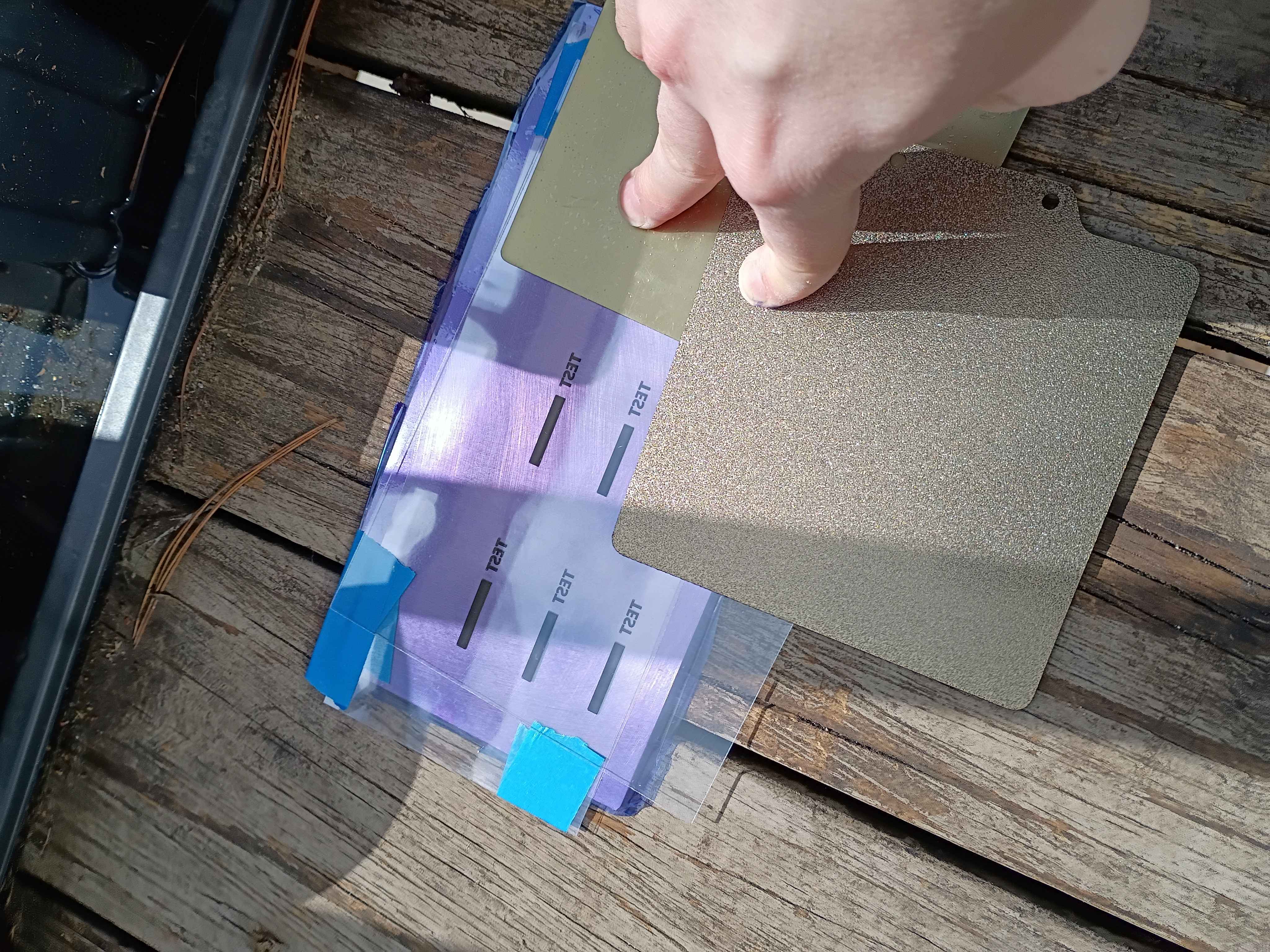
Printed and installed (with absolutely none of the correct hardware) the "pltr v2" plotter conversion to the old Ender3. Did a quick test and proved that it would work in theory to apply Sharpie as etch-resist for basic PCB production. Have to figure out how to generate the gcode for the mask with a preset X Y Z offset, but maybe I can cheat by zeroing the printer at a certain location. For reference the Sharpie lines are a bit under 1/32 inch wide, which I think will work for SOIC packages but probably not TSSOP. Still very cool. See video. 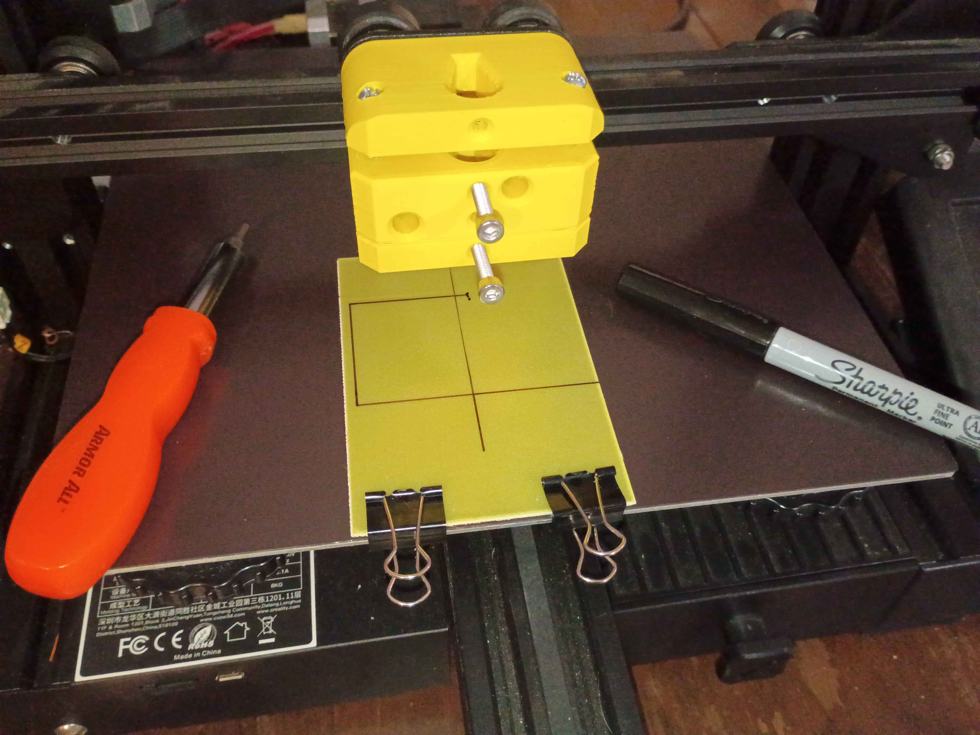
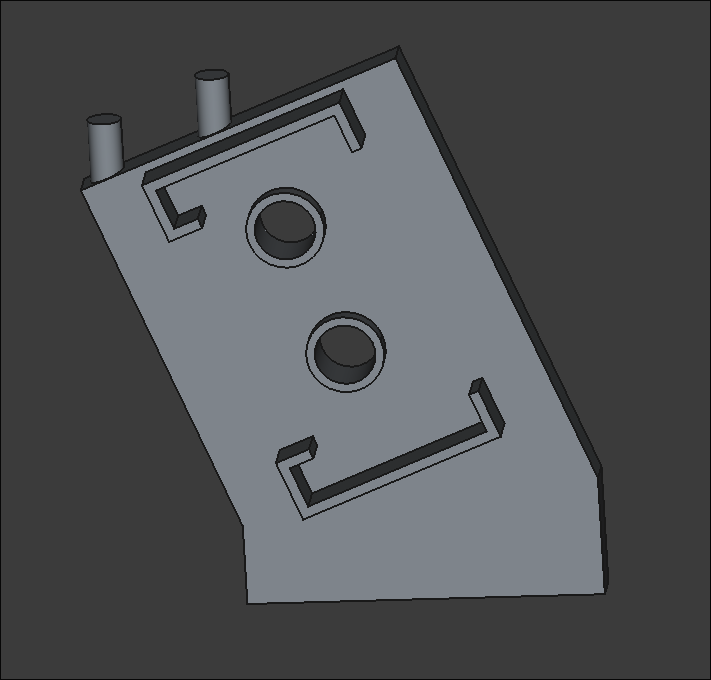
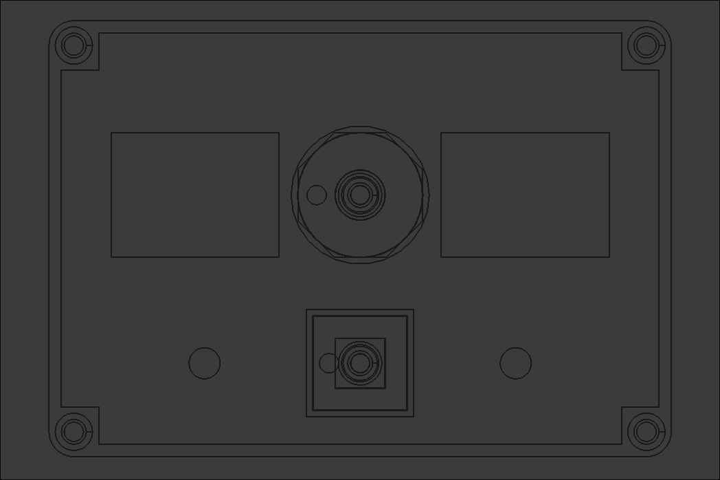
Mocked up preliminary button and housing components in 3D. Buttons need some kind of retention feature to prevent them contacting the eventual hall effect sensor. 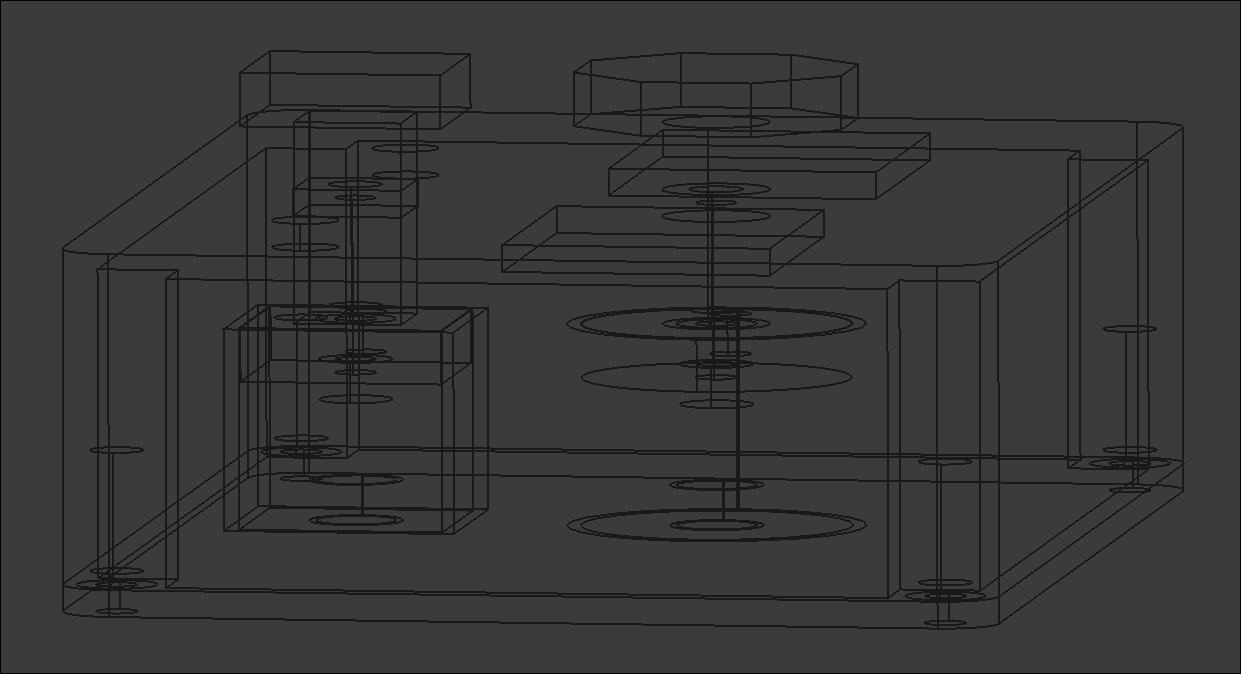
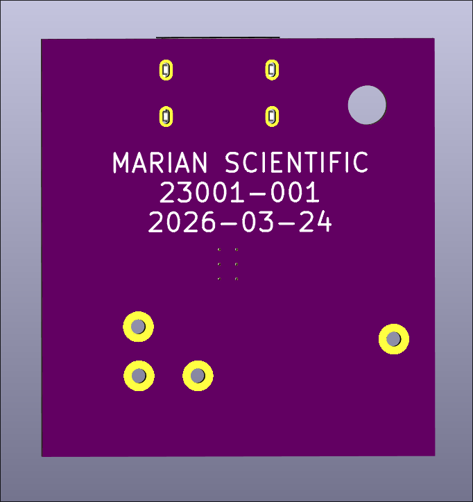
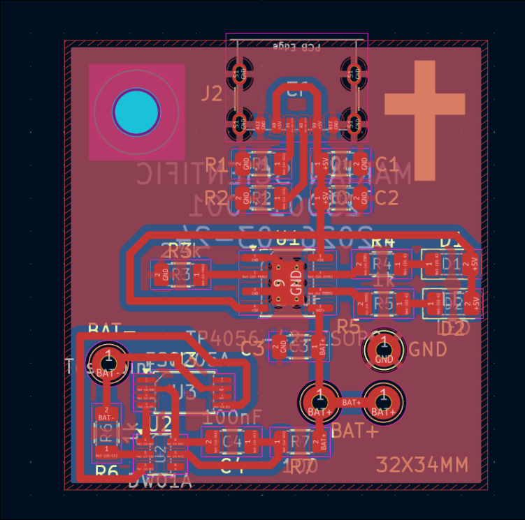
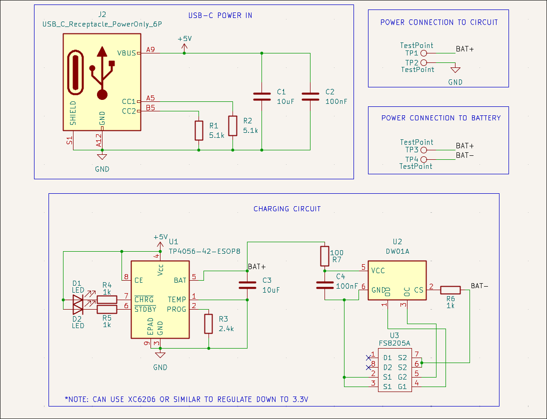
Designed USB-C LiPo charging and power delivery test board using TP4056, DW01A & FS8205. Ordered on OSHPark and saved full-size version as new MS KiCAD template for future use if the test board is successful. This will be the power basis for all near-term handheld math manipulatives. Design based largely on the linked schematic here. 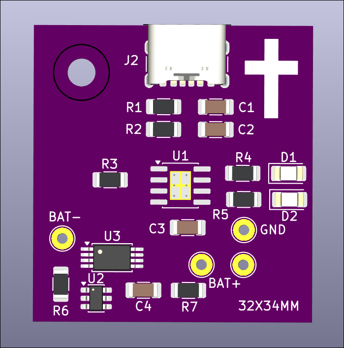
Updated printed config files to improve print quality and seemingly avoid some common print failures I was having. Reprinted 04002-001 and 04002-002 dog bag holder with a slightly larger internal diameter as a test print. 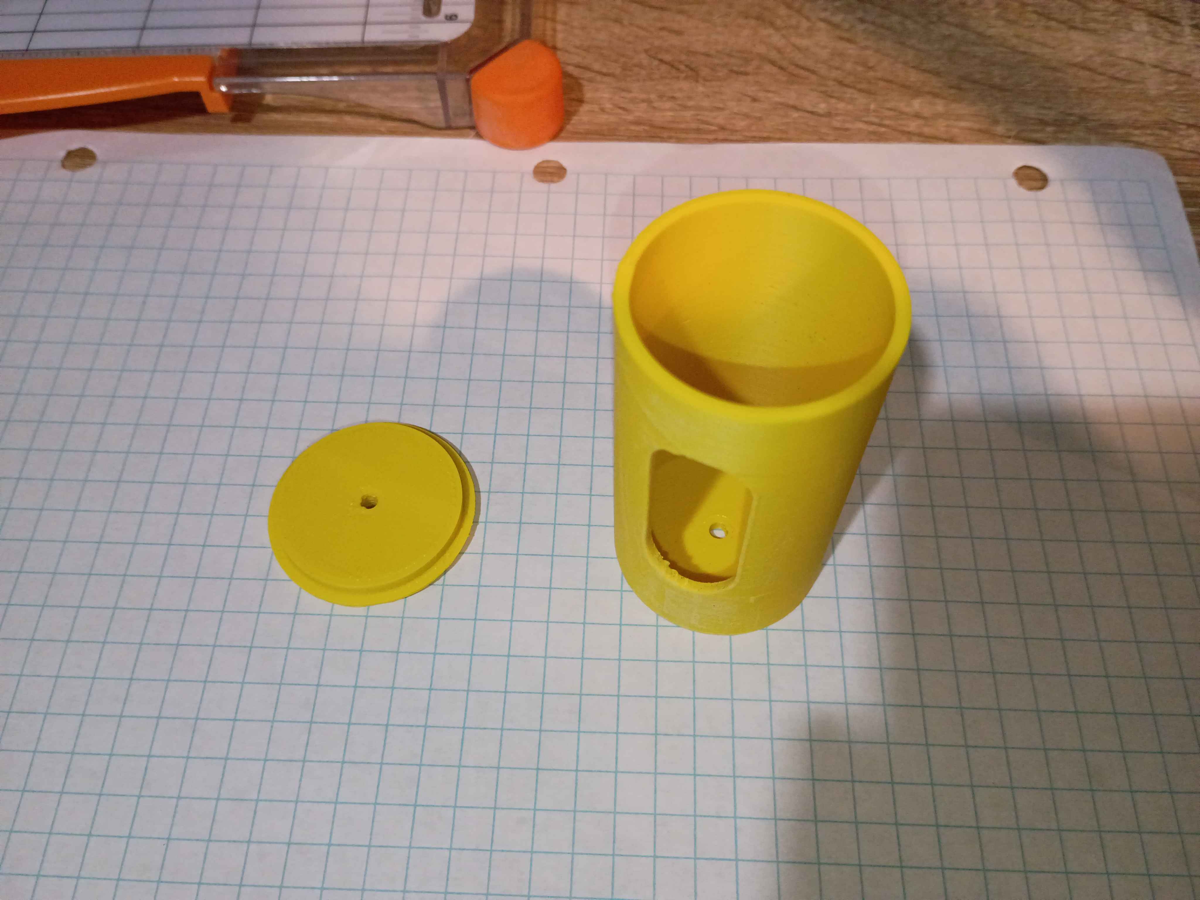
Designed and printed small (2cm) 3D geometric primitives for a client. Very rapid prototyping effort. 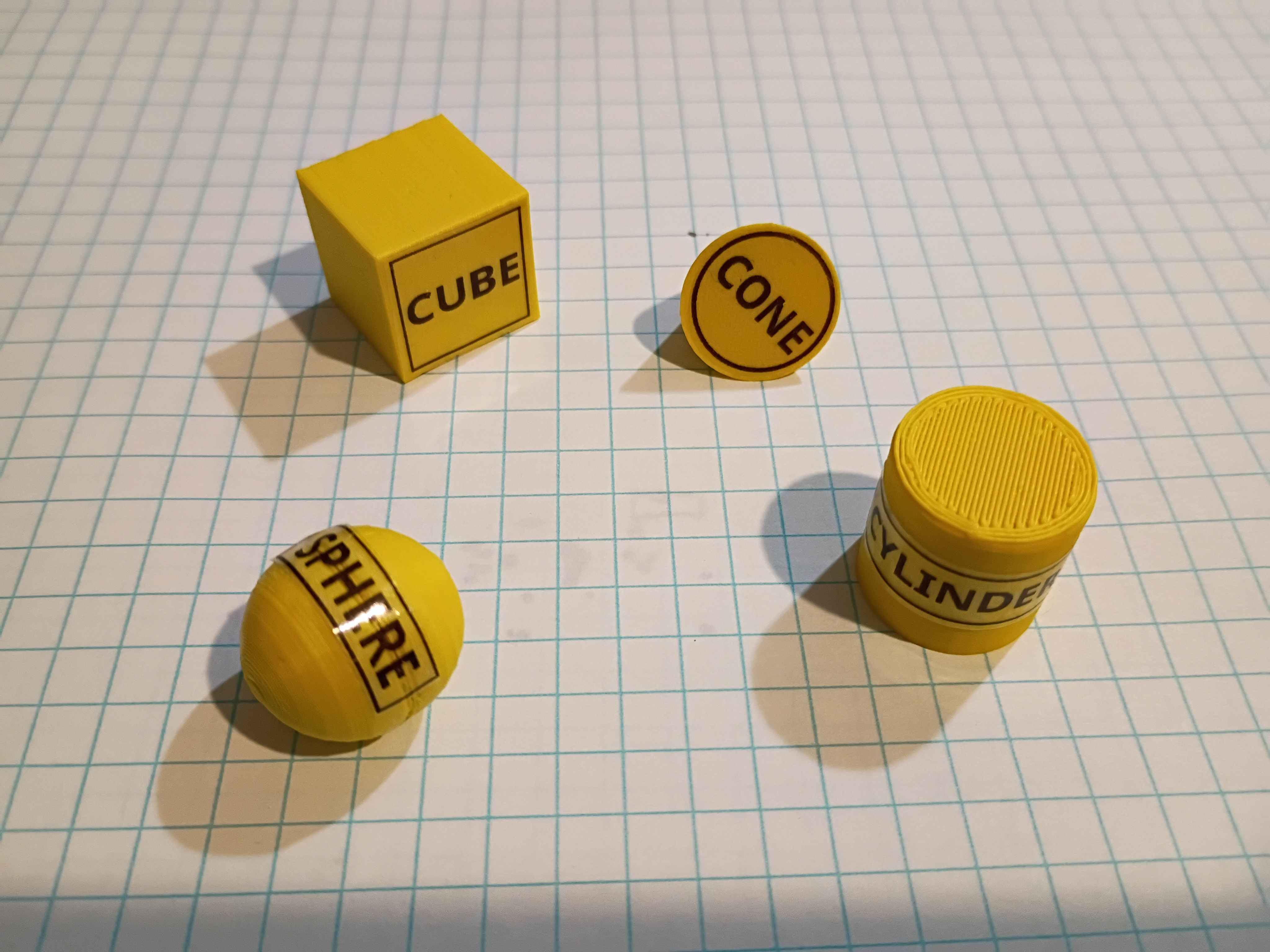
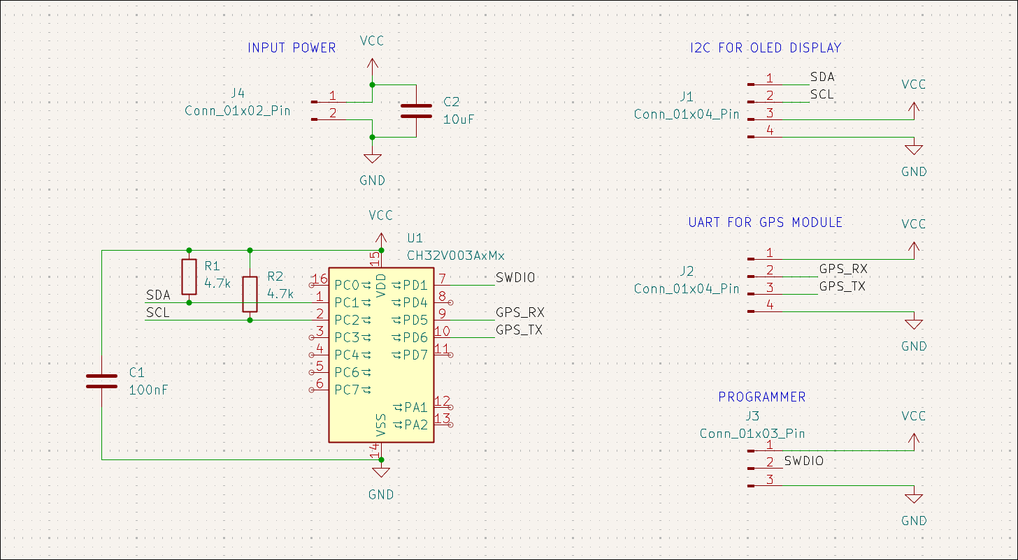
Designed UART GPS readout board to OLED display using CH32V003A4M6. 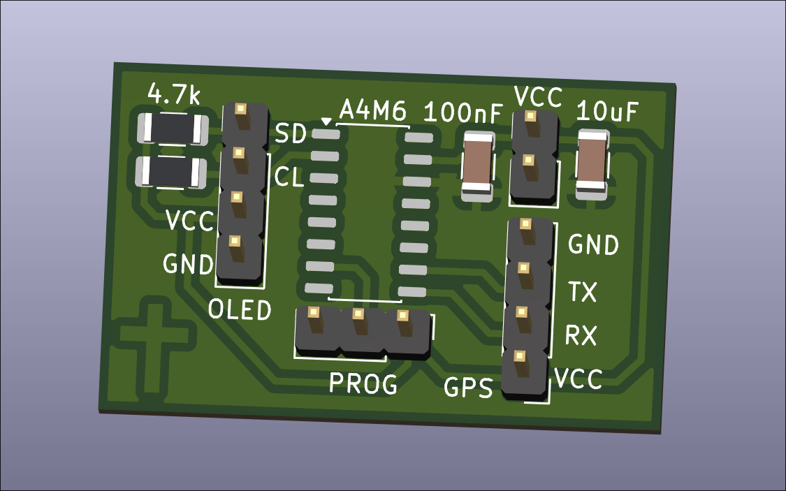
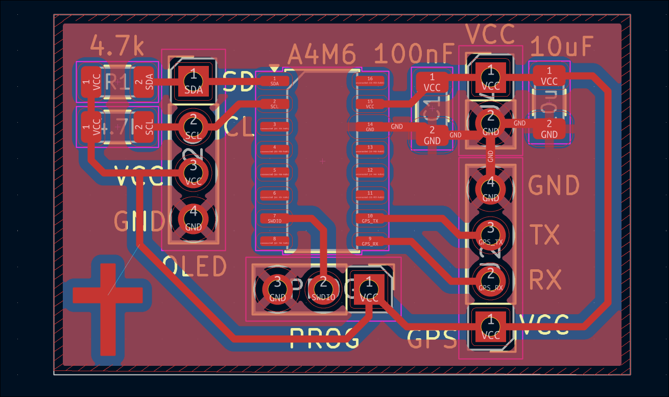
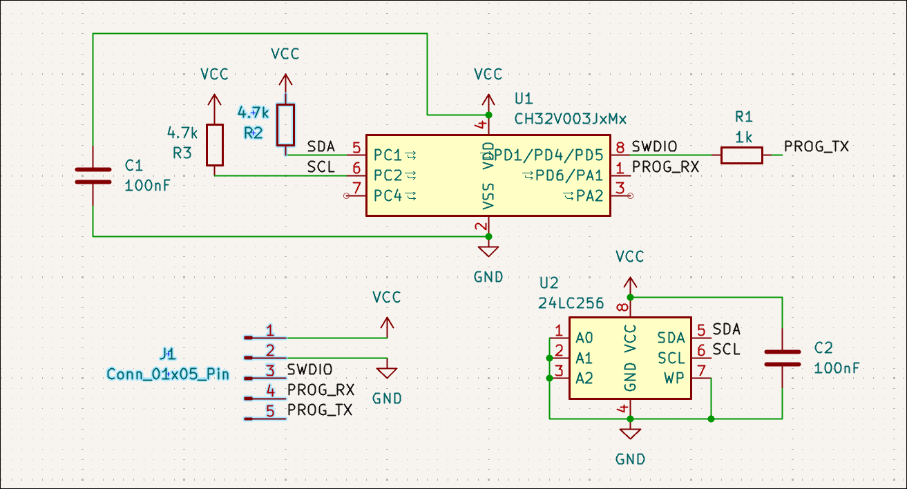
Designed simple test board for generic *24C256 (BL24C256) EEPROM attached to CH32V003J4M6. To be used alongside LinkE programmer for testing. 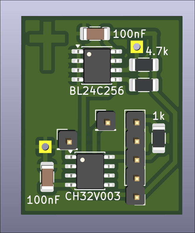
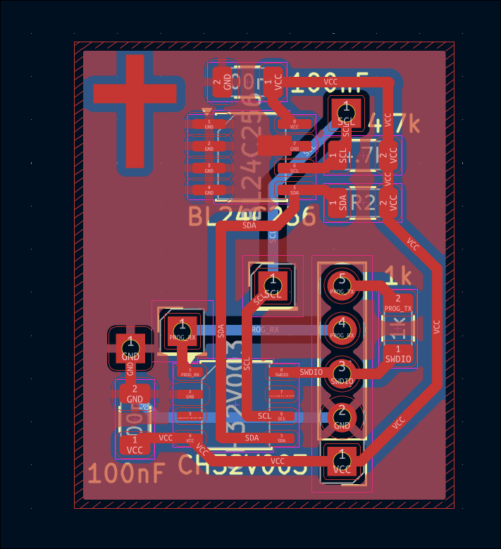
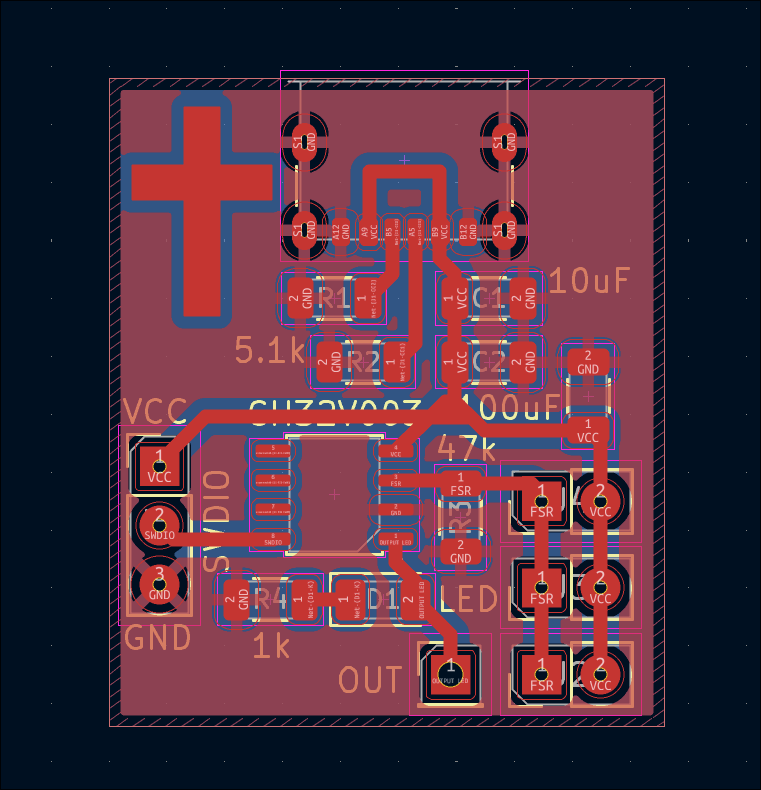
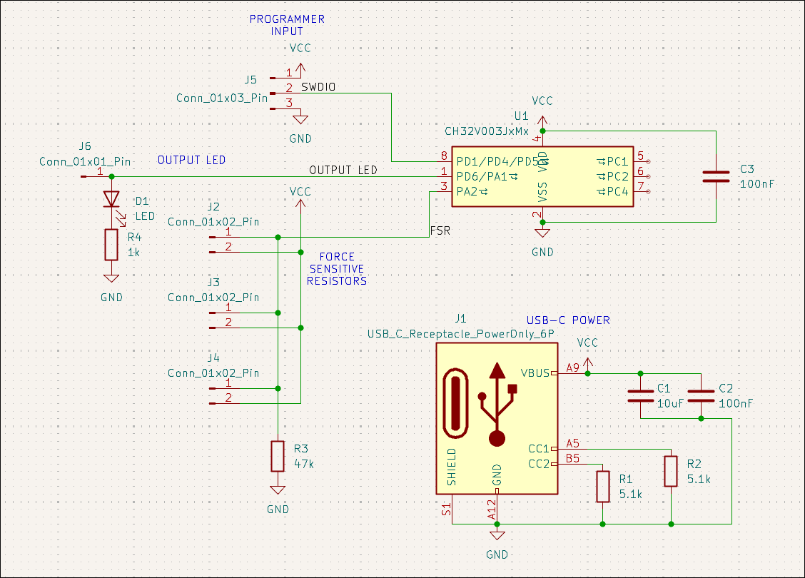
Designed force-sensitive resistor (parallel) weight measurement board that signals an output when the force is above some threshold level. 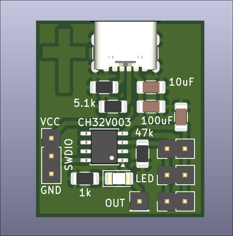
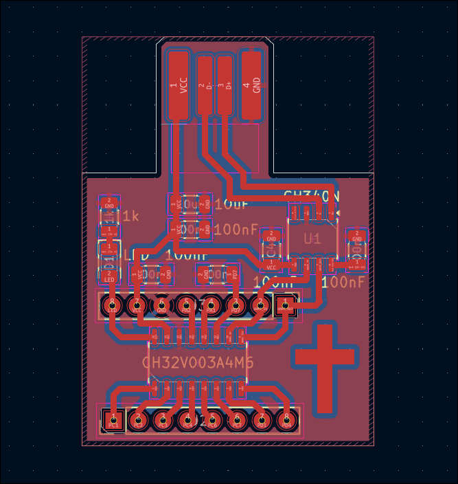
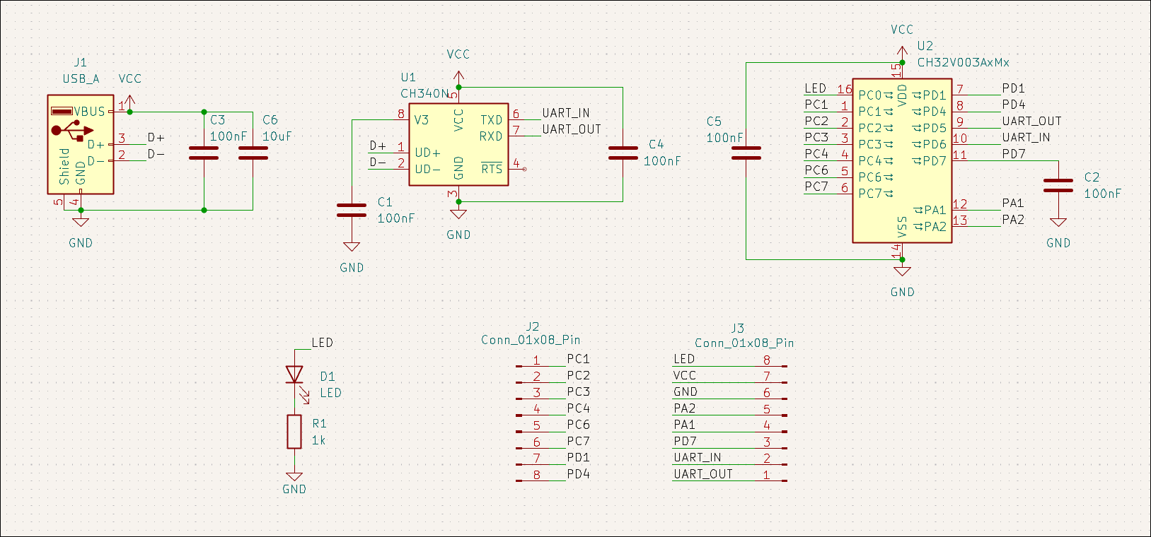
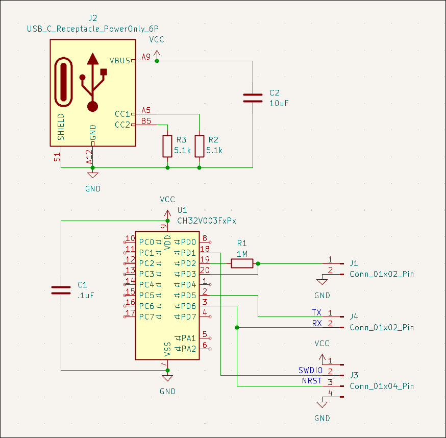
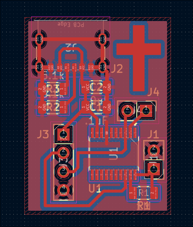
Designed 03007-008 CH32V003A4M6 development board with a PCB board-edge USB connector and a CH340N as a test of both. 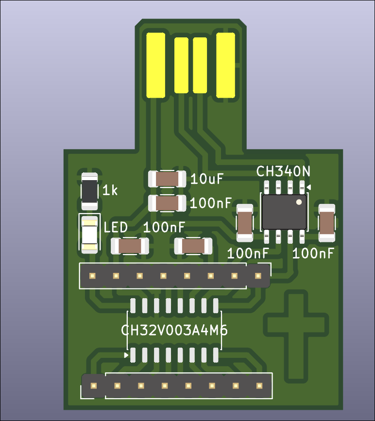
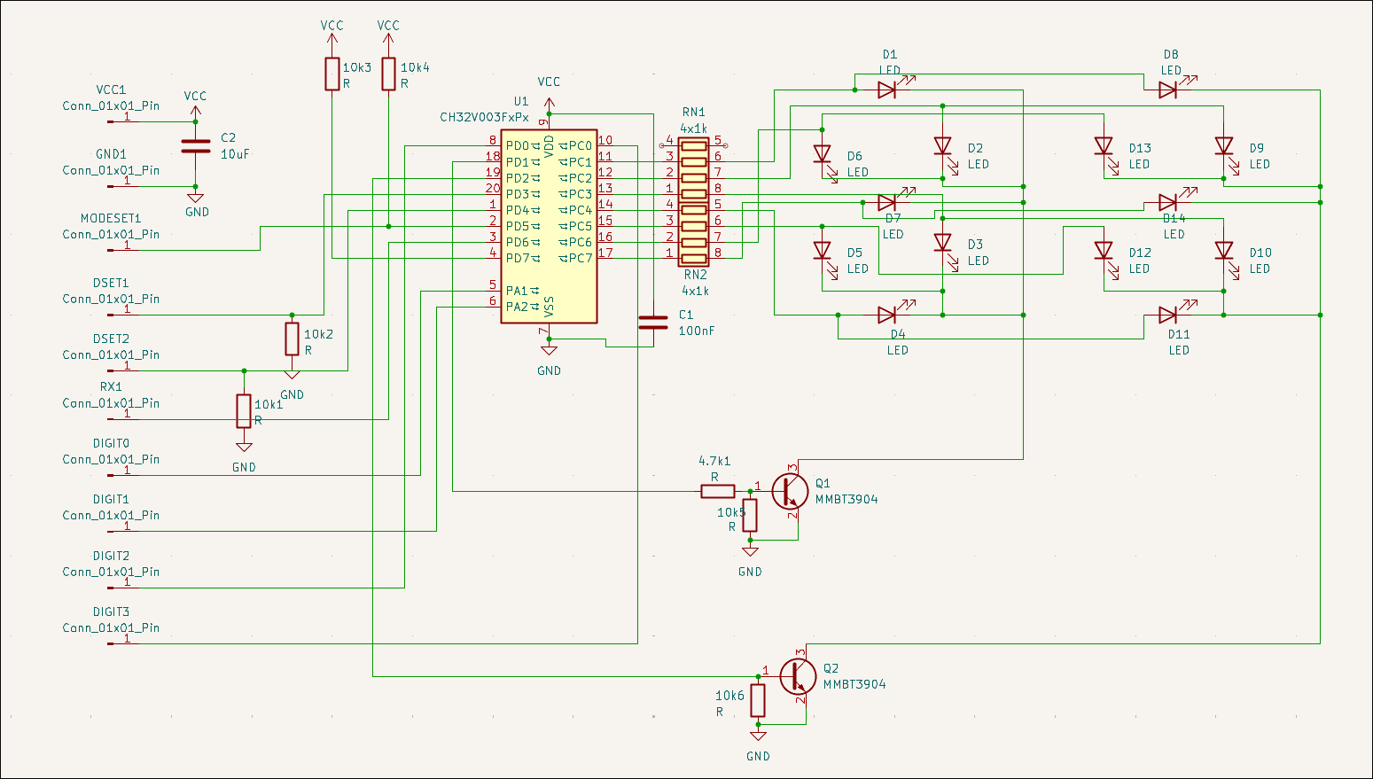
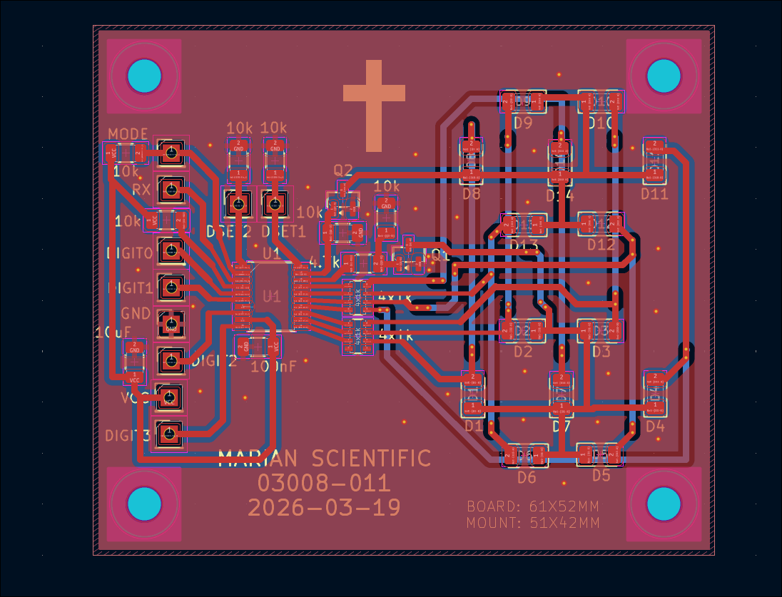
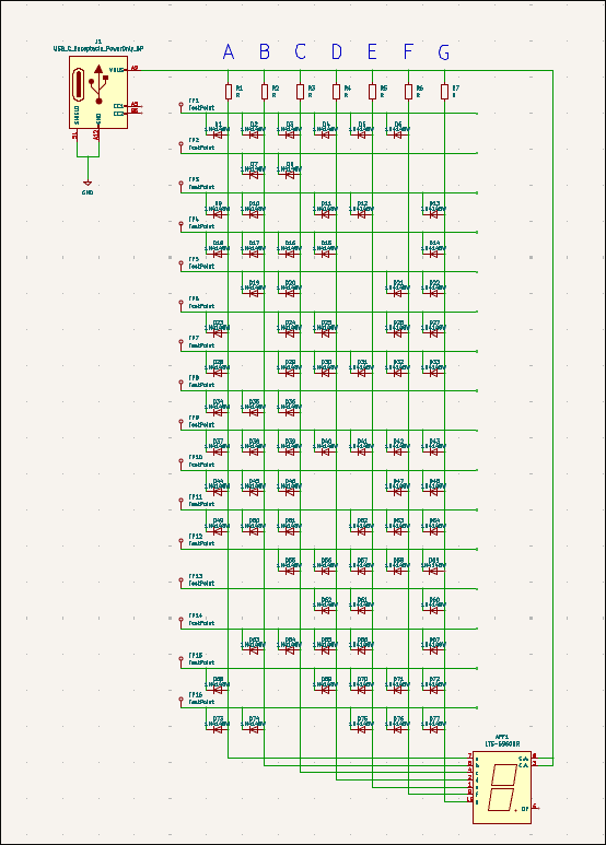
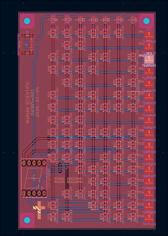
Designed double 7-segment driver and controller circuit (03008-011), can take inputs either from RX or binary digits using MODESET and LATCH pins. The 7 segments are constructed from discrete LEDs, set in slightly opaque epoxy resin. 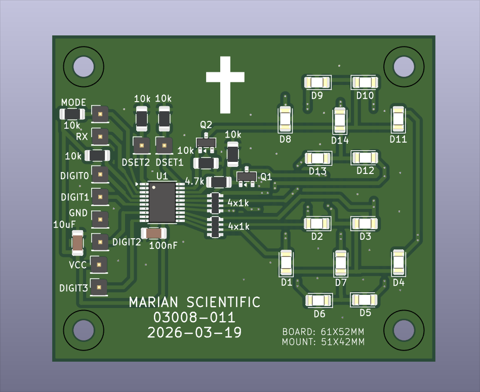
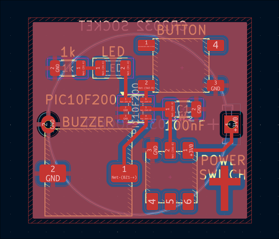
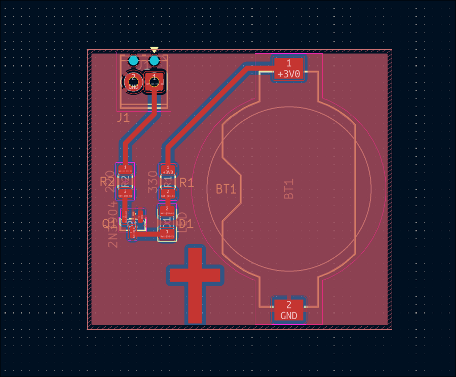
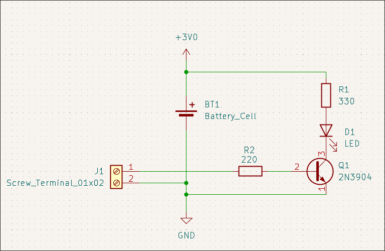
Designed 03014-001 hyper minimalist kitchen timer. Single LED output (flashes number of minutes remaining in quick succession every few seconds), single button input (one push to increment timer, long push to reset, single push to reset on alarm), buzzer, CR2032 battery. 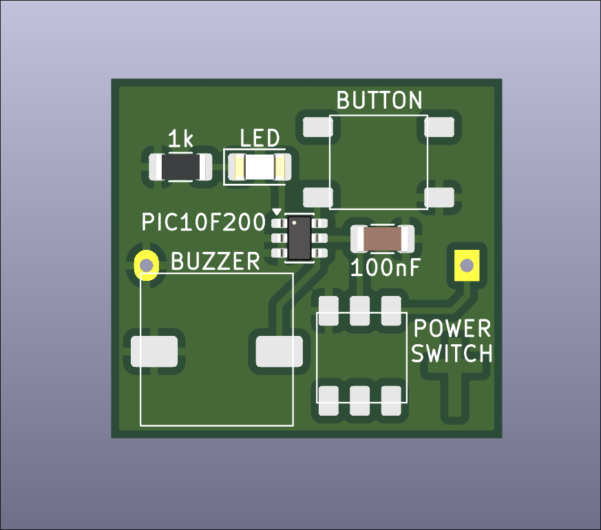
Designed simple 03012-004 PICKIT programmer adapter board to POGO pins for programming/testing of 03012-003 as a test of the process. 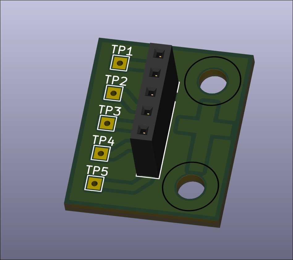
Created GitHub landing page for project with BOM, photos, and links.
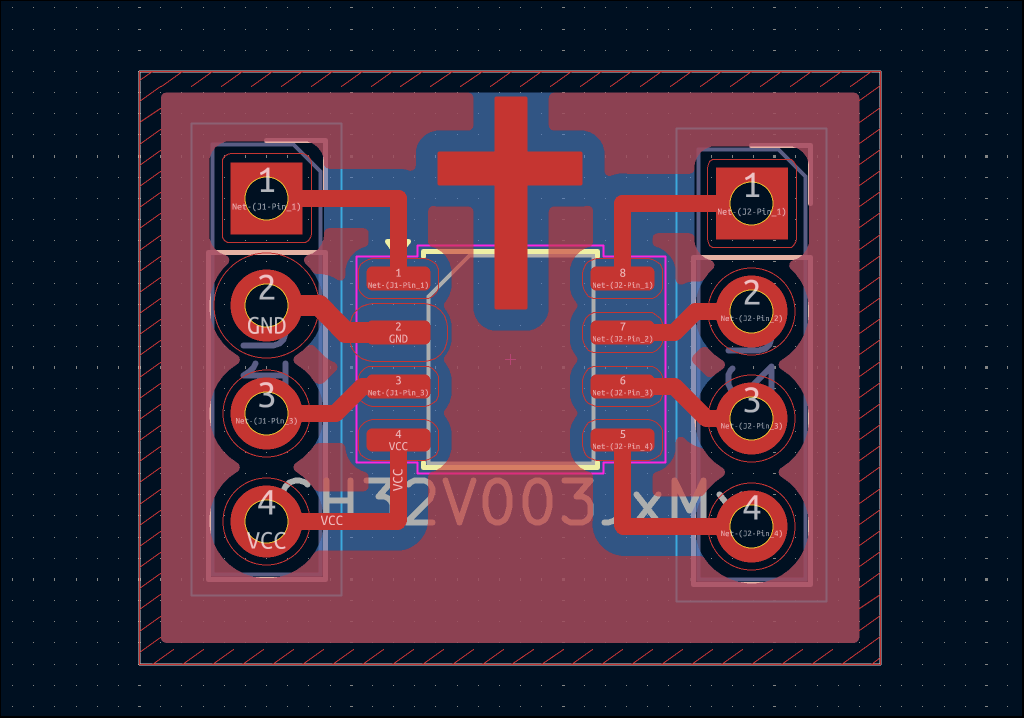
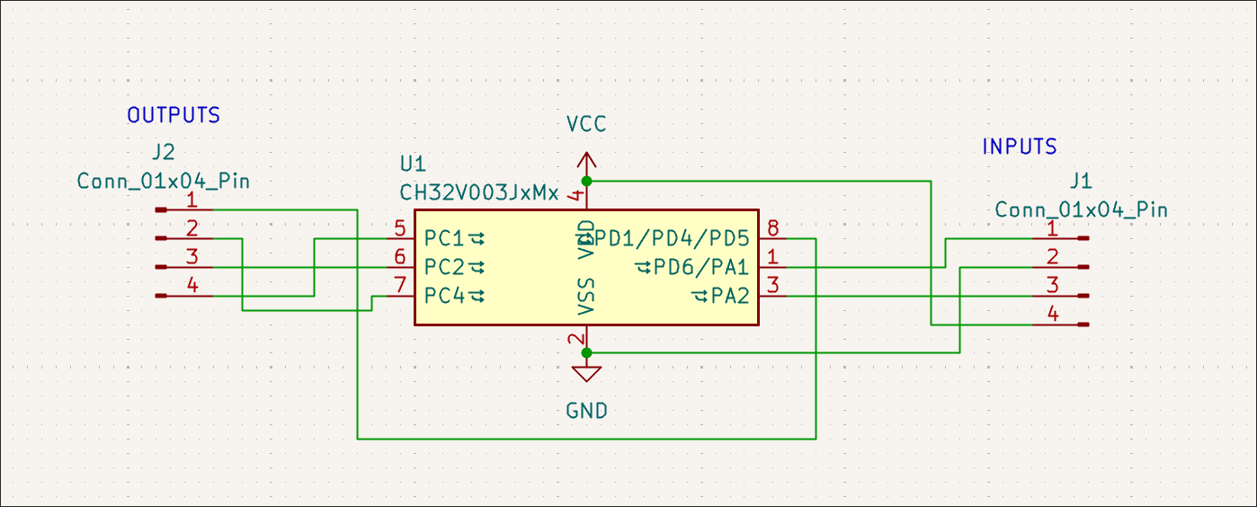
Designed 02005-004 PCB which is seemingly just a SOP8 breakout board, but also with a CH32V003J4M6, you can dedicated 2 pins to power/ground, 2 to input signals A and B, 2 to a mode setting 00/01/10/11, and then get different output signals on the 2 remaining pins: NOT A, NOT B, A OR B, A NOR B, A AND B, A NAND B, A XOR B, A XNOR B. 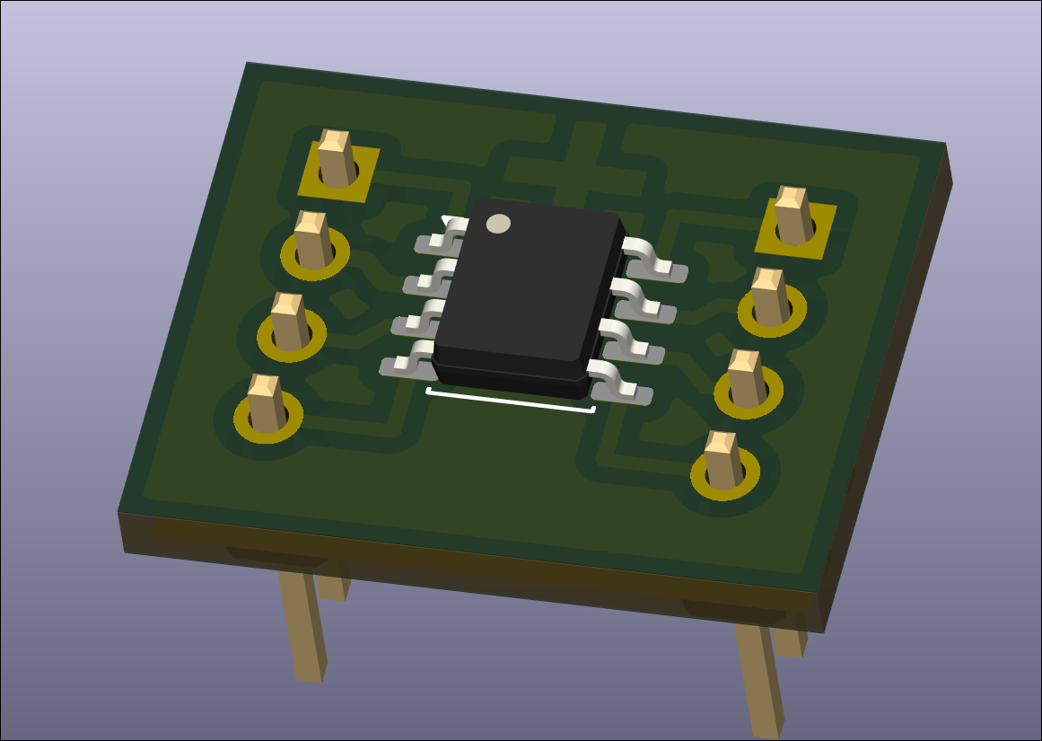
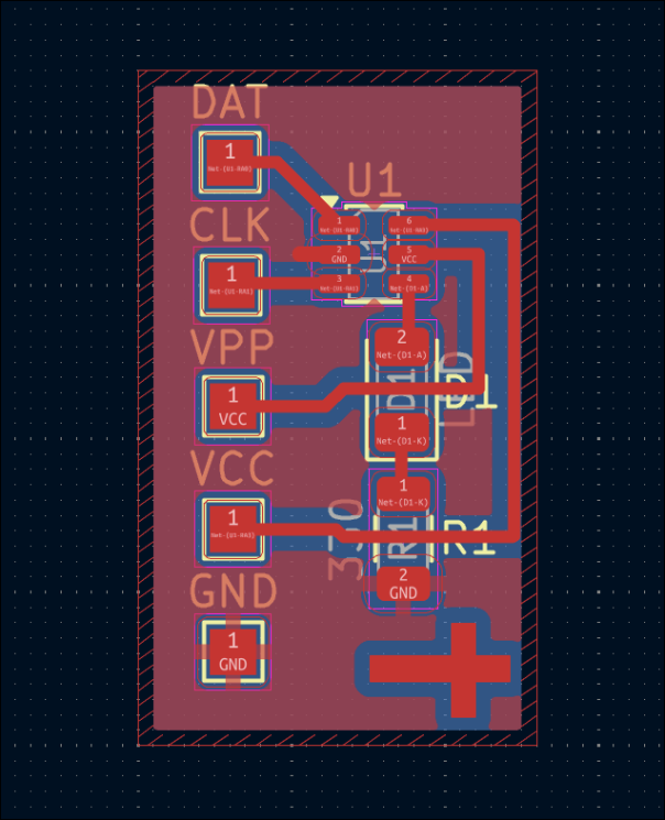
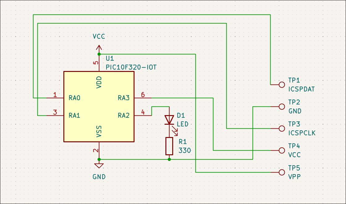
Designed (03012-003) extremely small dev board for PIC10F32* (or 20*) that will be used to test pogo pins, the software toolchain, and use of 1206 components to jump over traces (although that was not required). 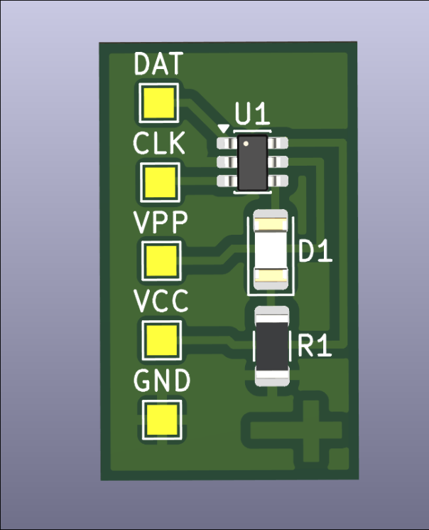
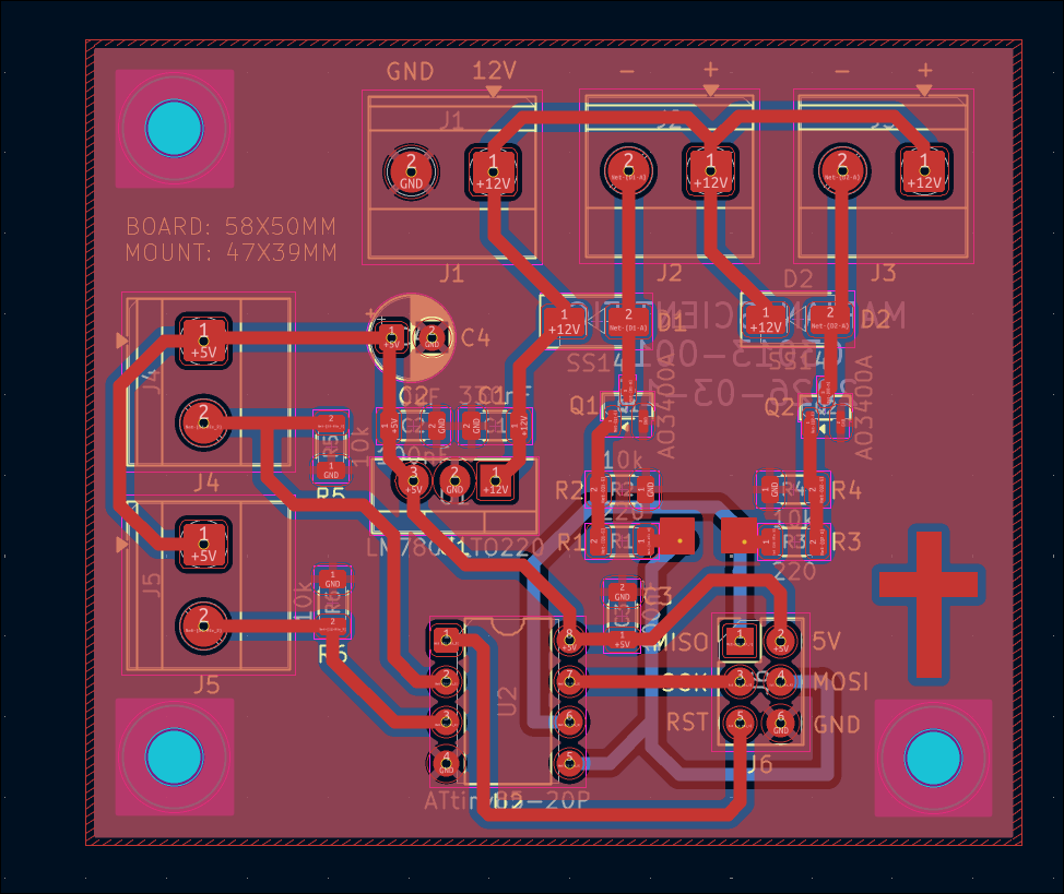
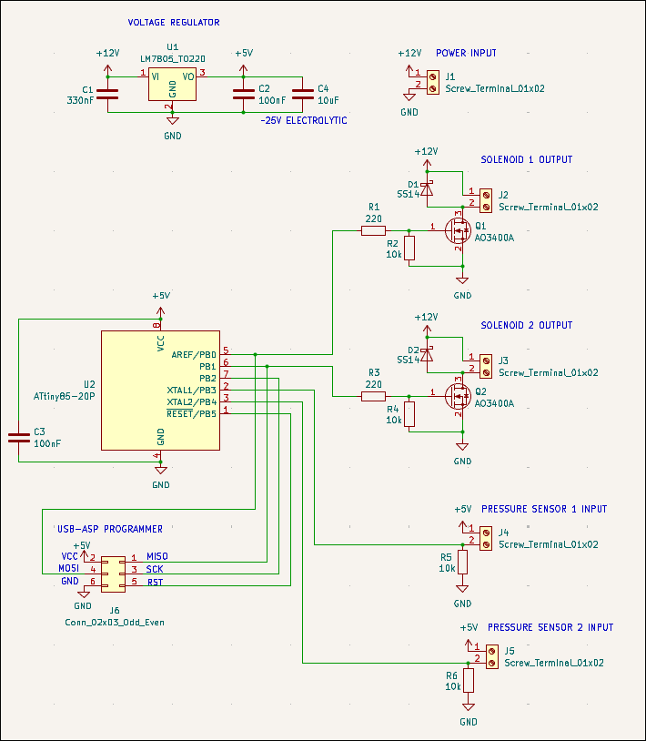
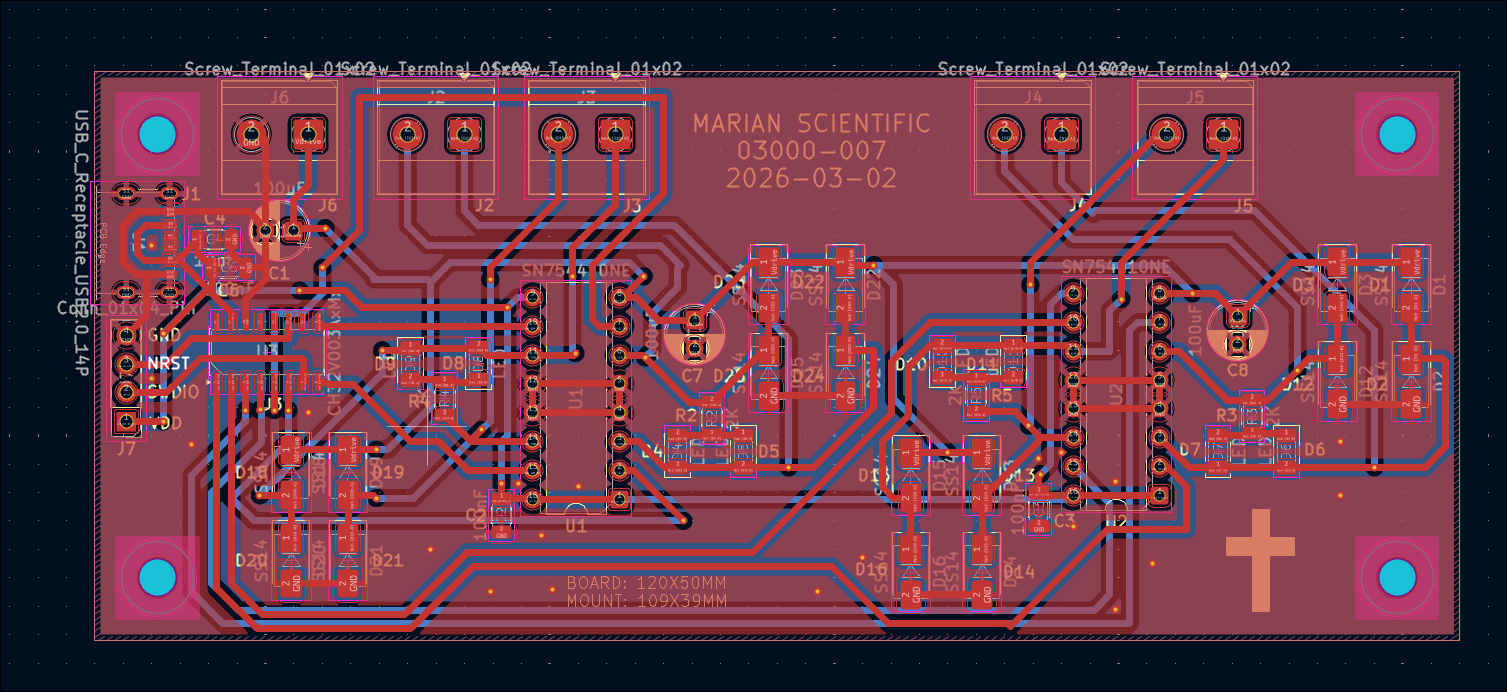
Designed 03013-001 watering can fill board, which will use 2x force-sensitive resistors to determine if 2x watering cans are filled, and use 2x 12V solenoid values to fill them from tap pressure, all controlled by an ATTiny85. 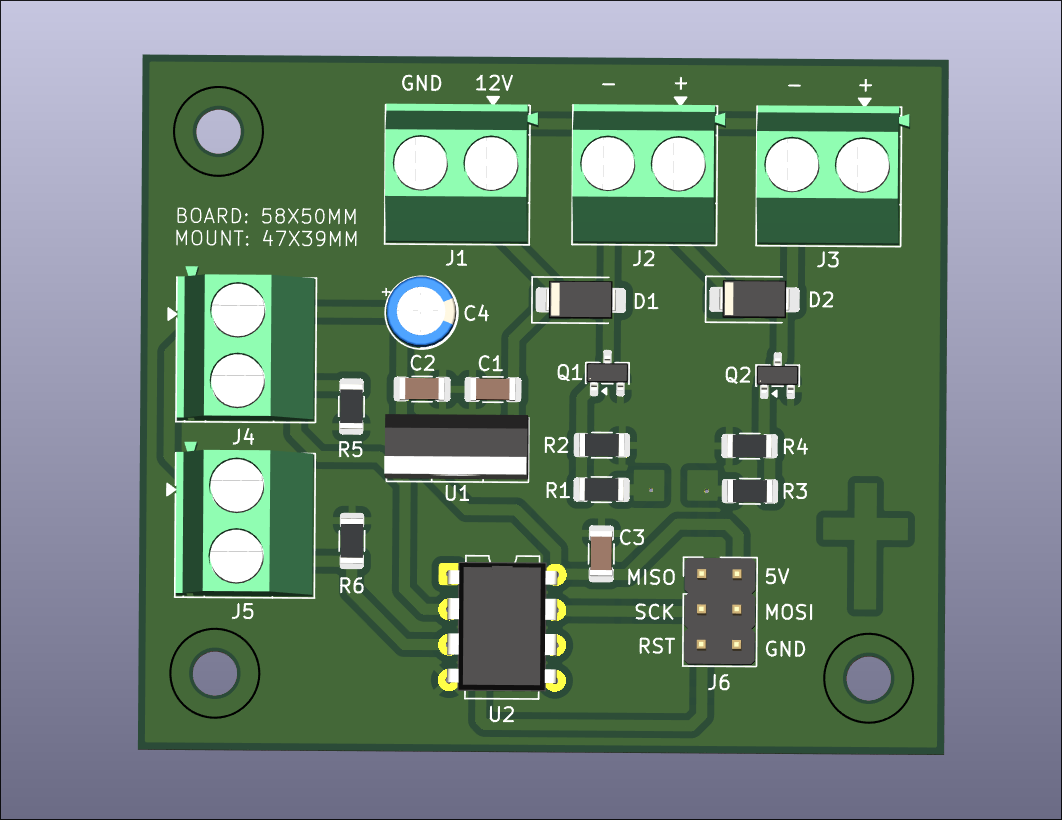
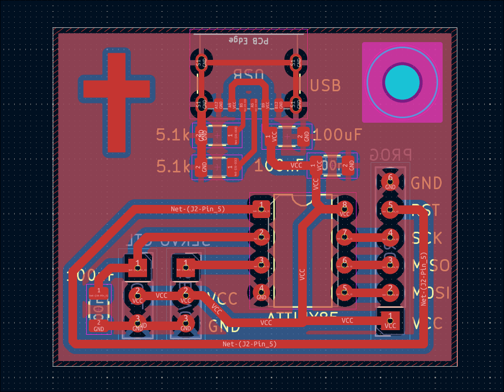
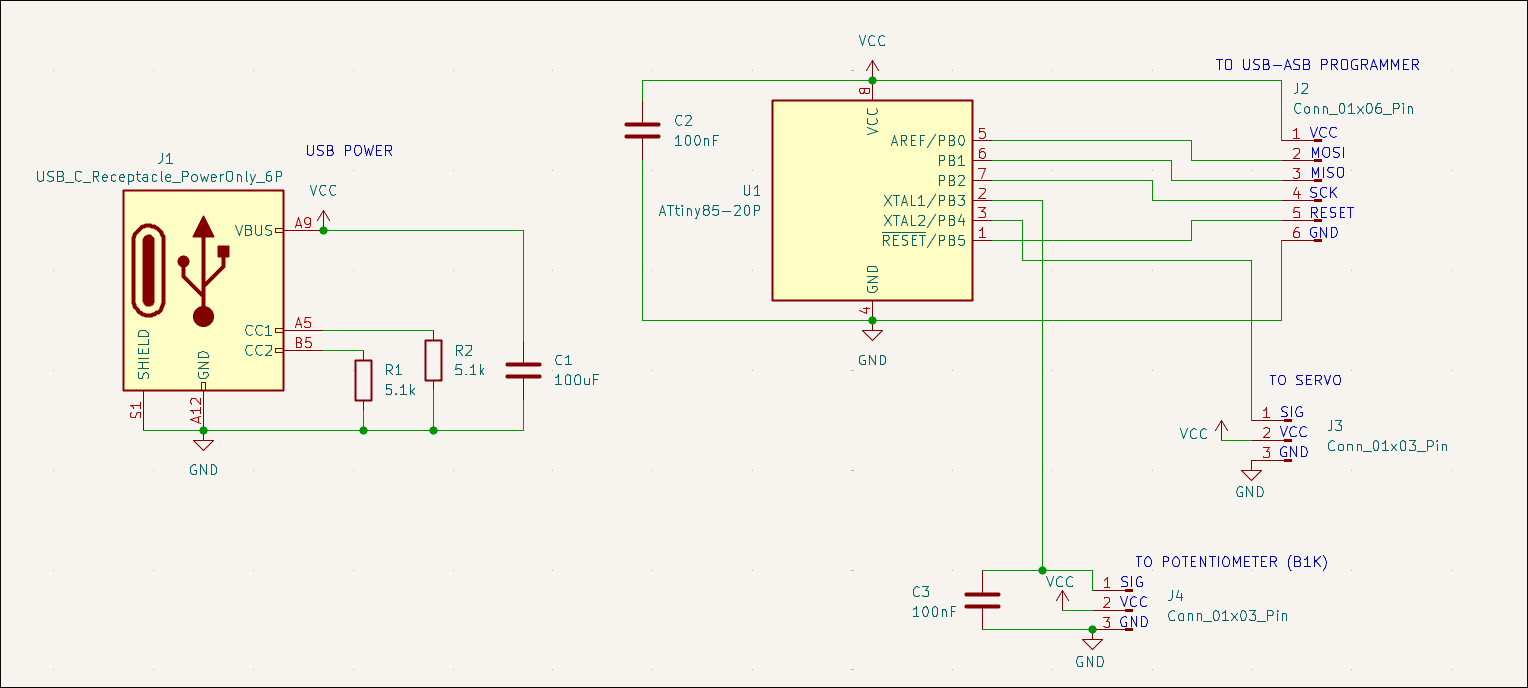
Designed 03012-002 reprogrammable servo motor tester with potentiometer input. 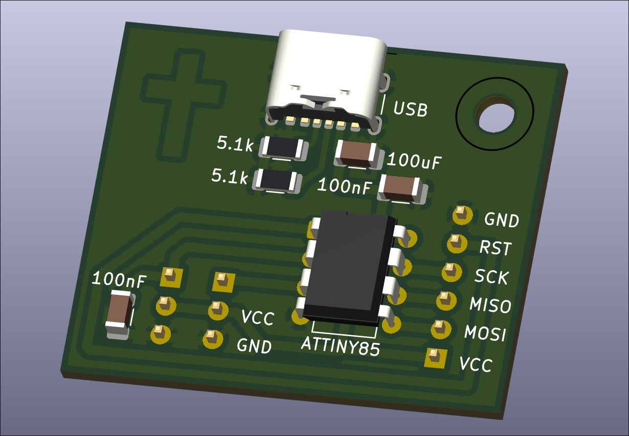
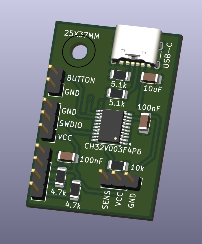
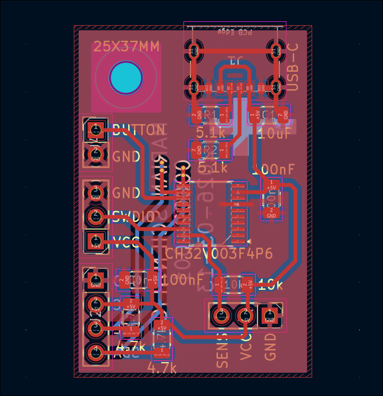
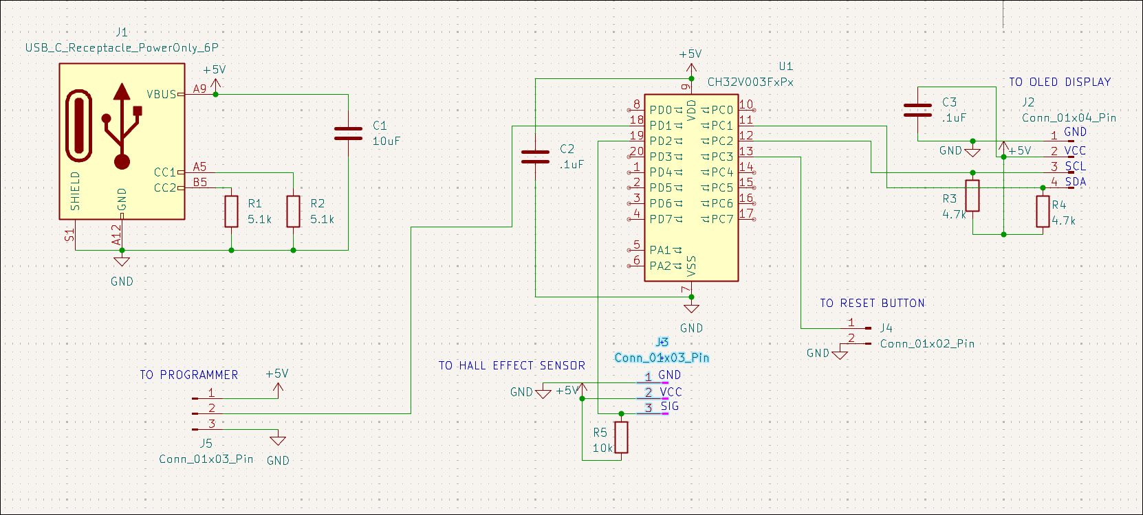
Designed 00002-001 PCB to track rotations of coil winding jig with OLED display output. 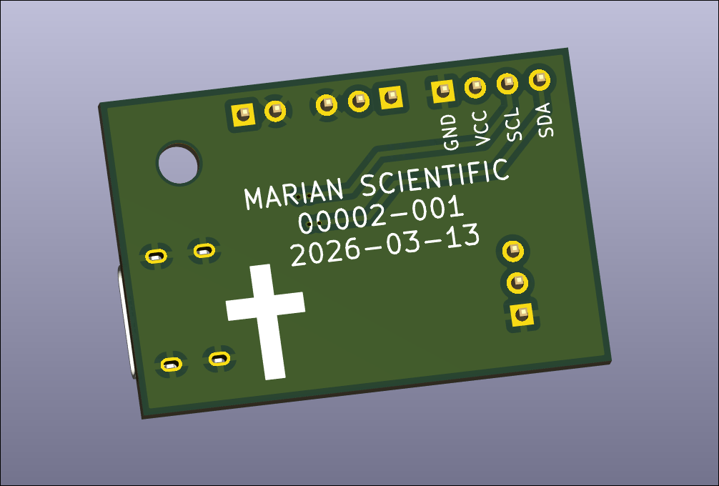
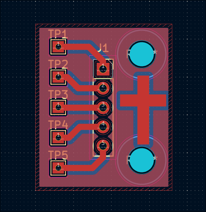
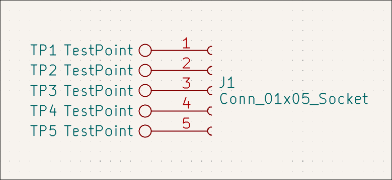
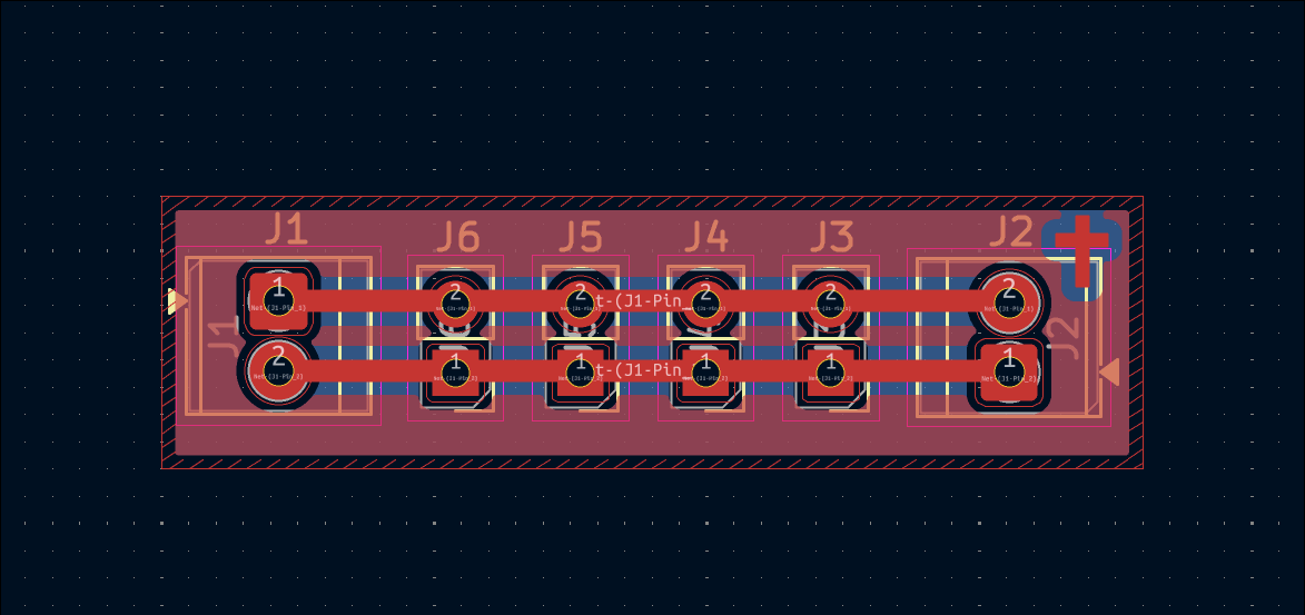
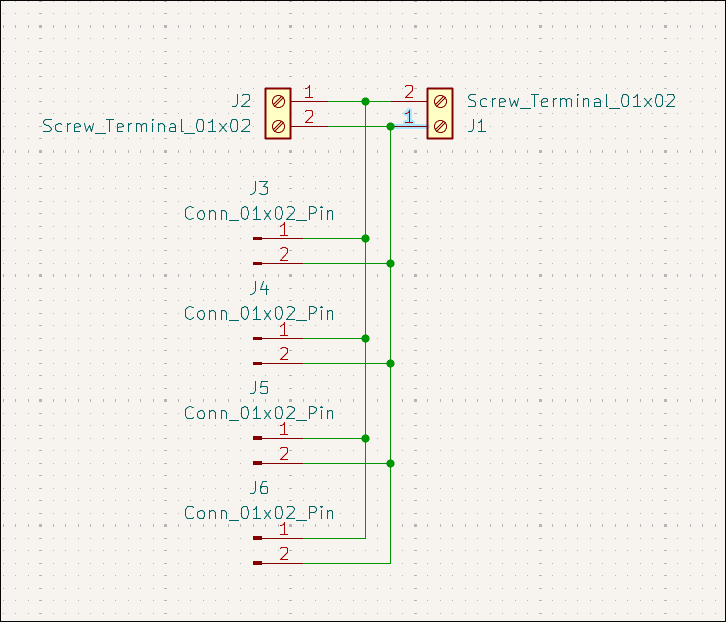
Designed very simple but likely very useful screw terminal / header pin breakout connector board. 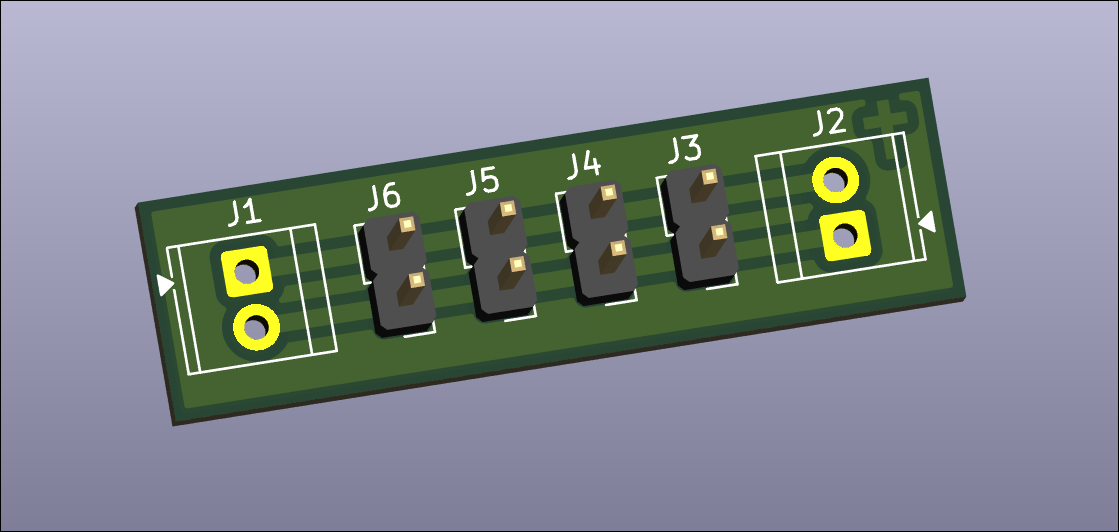
Designed Pi Zero hat for balcony garden pump control. 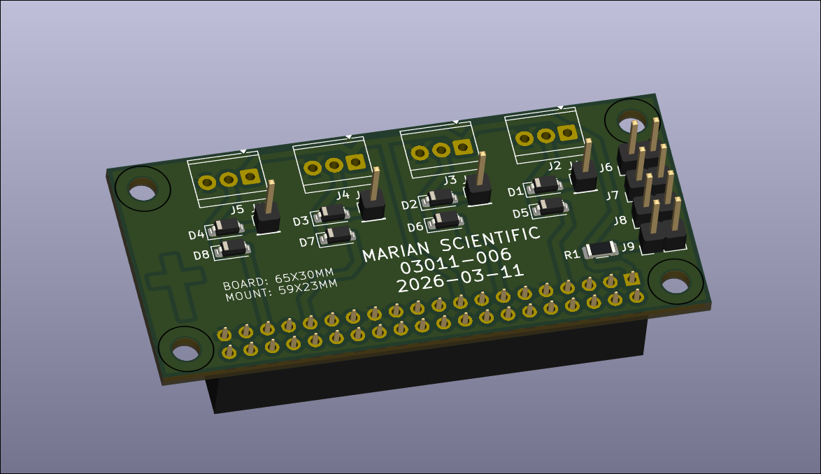
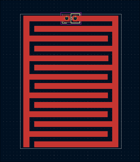
Designed interleaved comb trace board design for both capacitative and resistive moisture detection (03011-005). 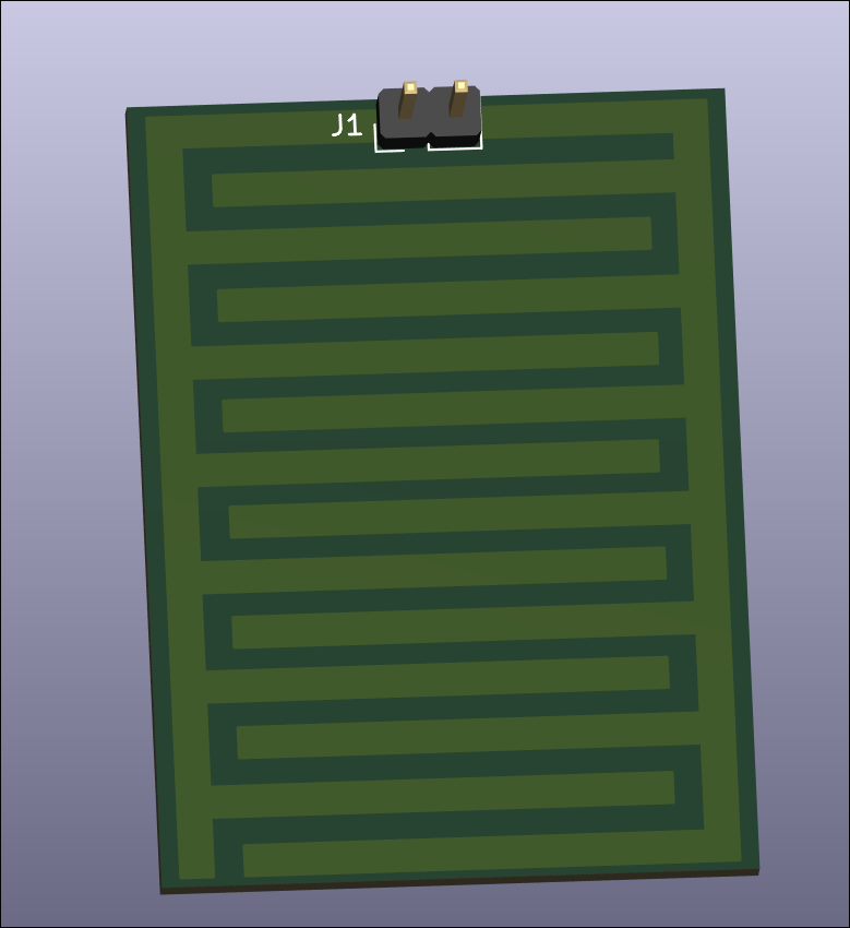
Designed very small capacitative water detection control circuit with an embedded ch32v003 microcontroller for detection, processing, and reporting. This also needs an external capacitor device to make the actual measurements. 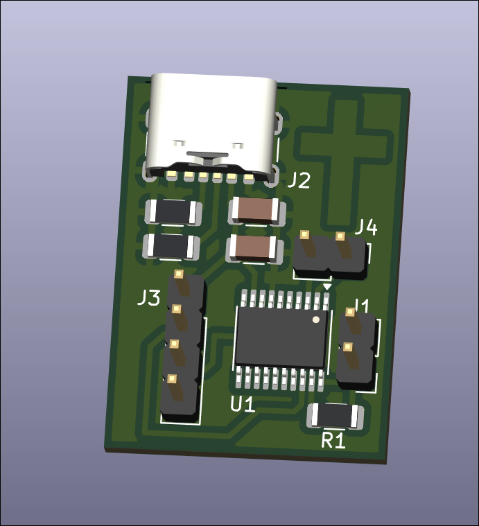
Designed very small resistive water detection control circuit. It needs to be plugged into some expansion board or non-electrolyzable probes. It returns a digital output on a closed circuit. 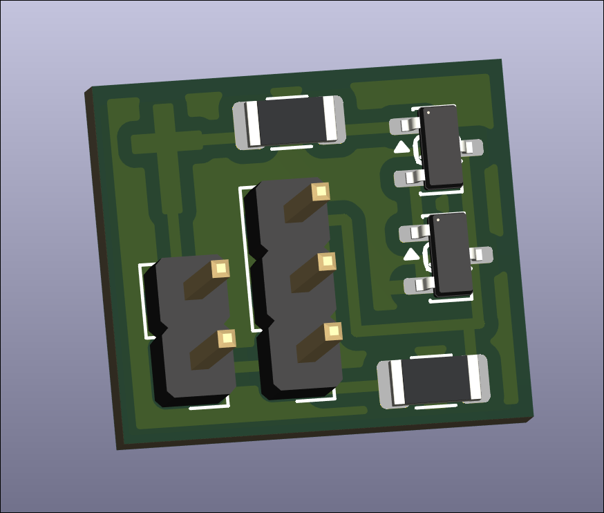
Designed servo control board (03012-001) and ordered on OSHPark. 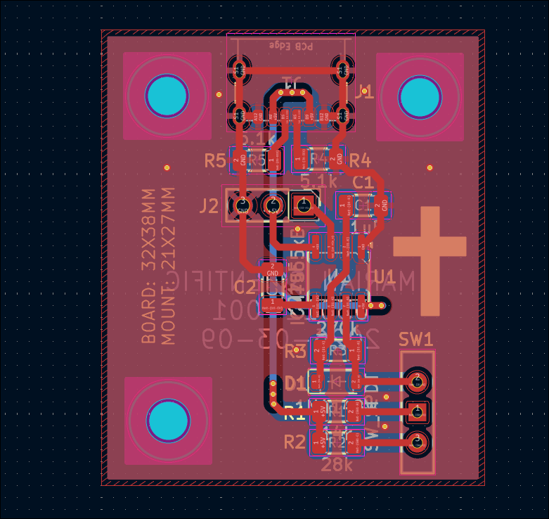
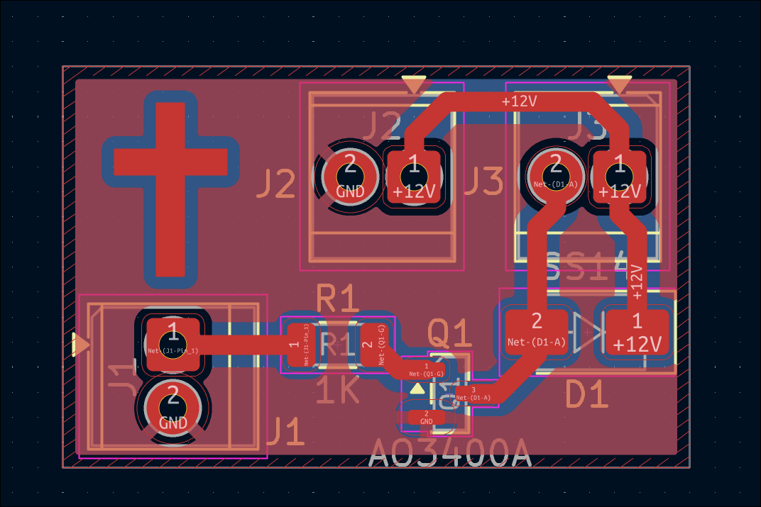
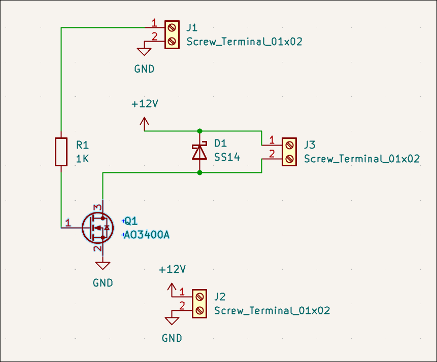
Designed alternative to 12V relay circuit using a single N-channel MOSFET (03011-002). This can be used to drive the water pump from a GPIO pin. 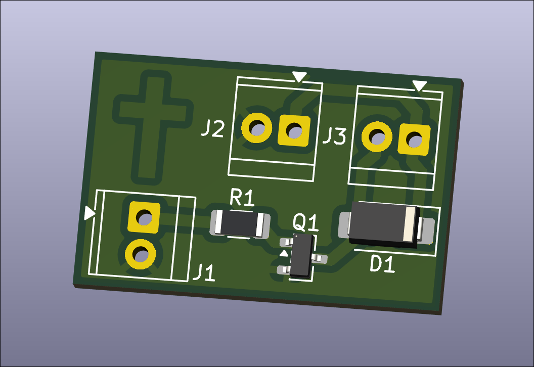
Designed water pump control relay breakout board for balcony garden. This is a nearly 1-1 drop in replacement for what I currently have on a protoboard and used successfully last summer. 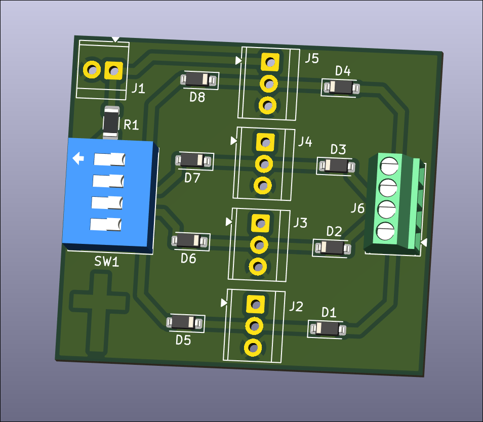
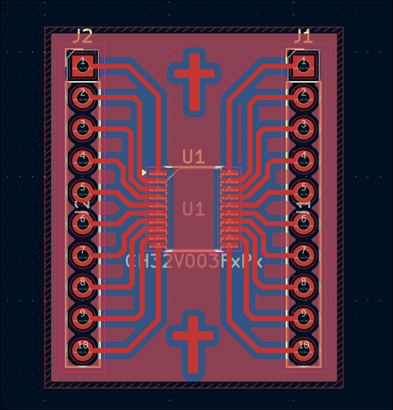
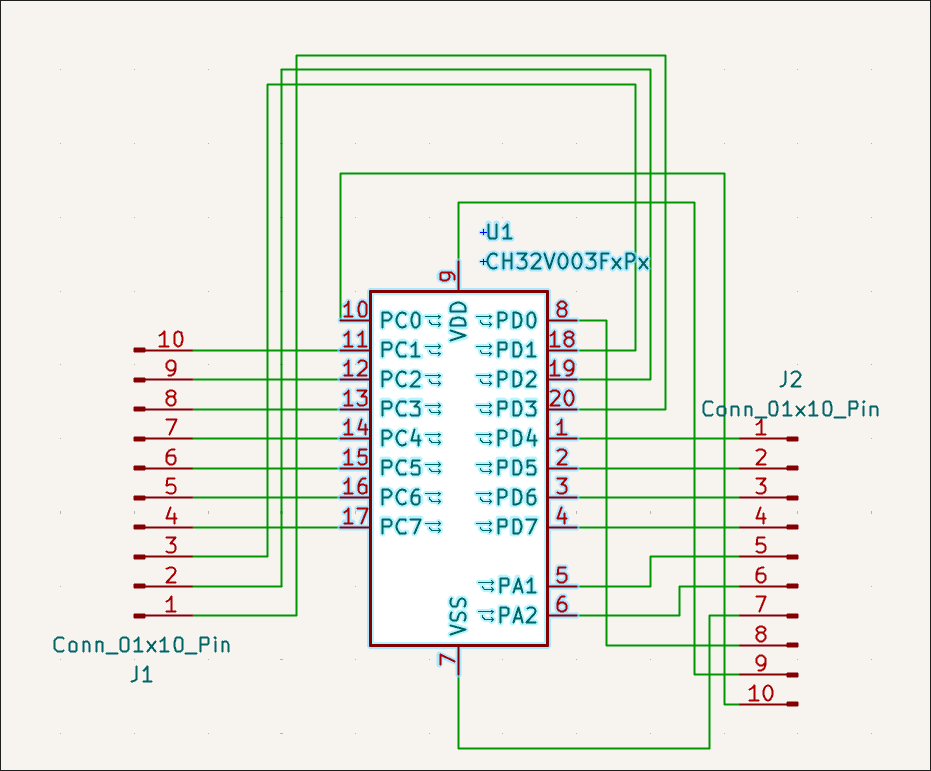
Designed CH32V003F4P6 (TSSOP-20) breakout board. 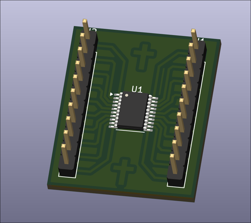
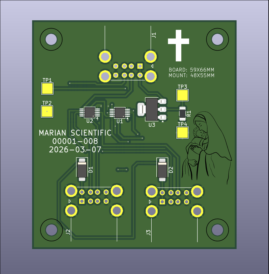
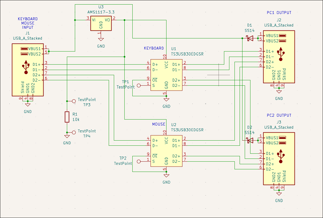
Designed USB mouse & keyboard splitter board (00001-008) for the CNC PC control. Likely will not purchase. 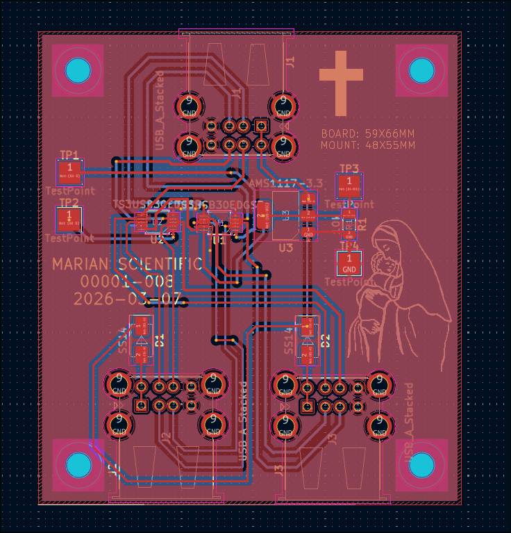
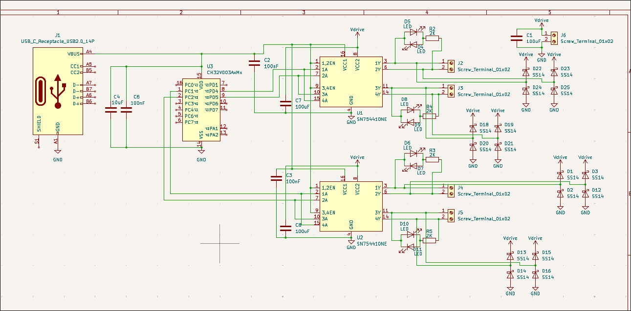
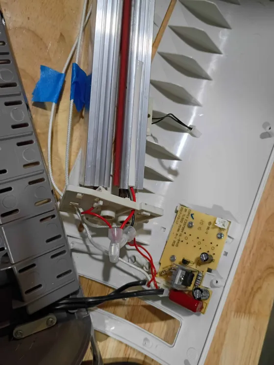
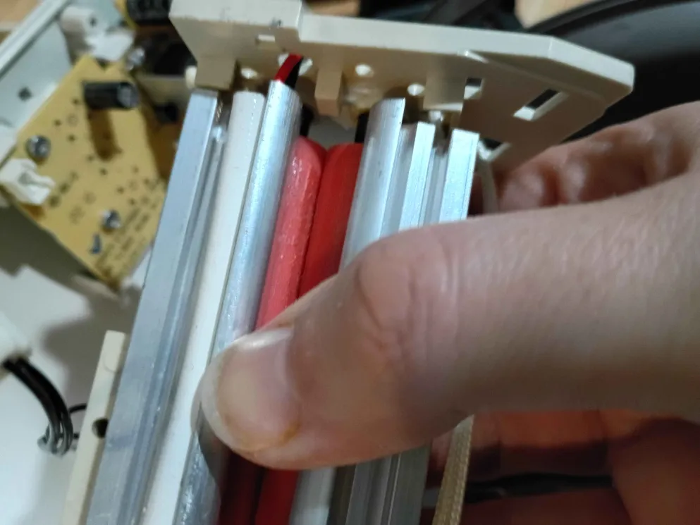
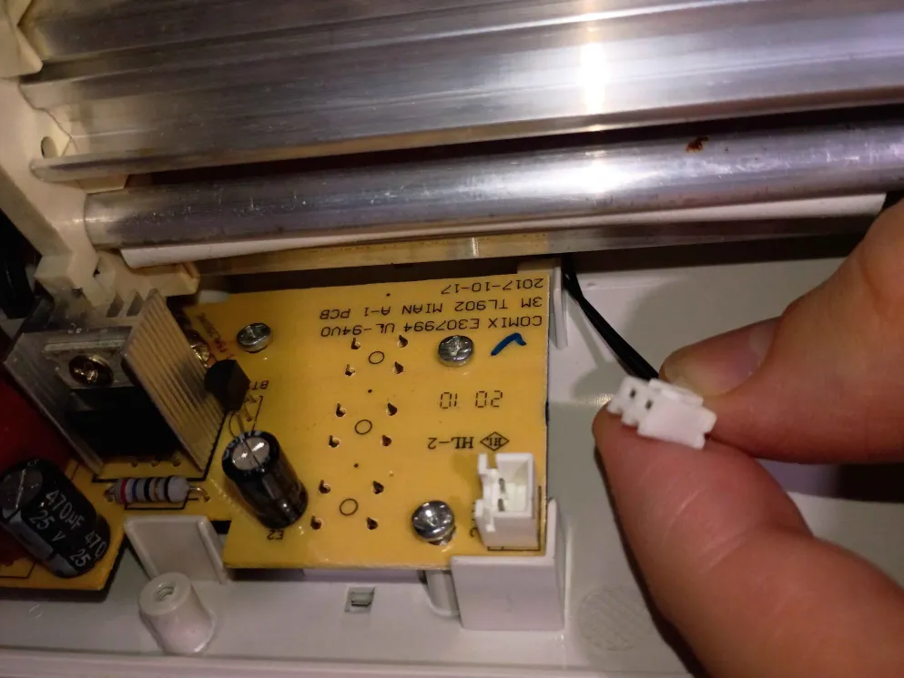
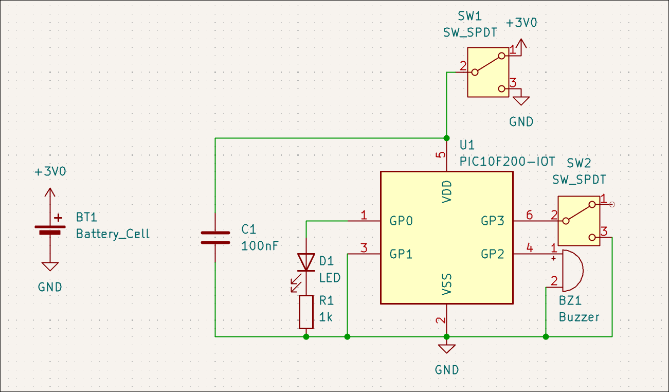
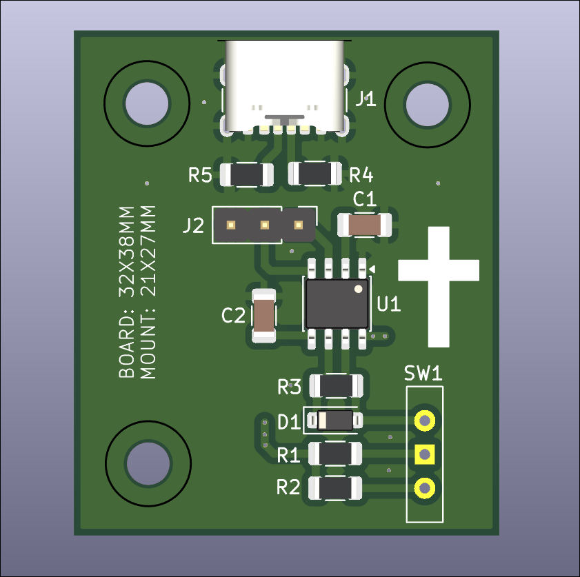
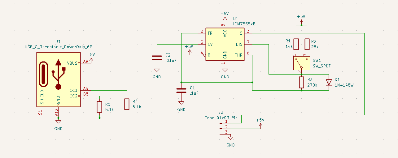
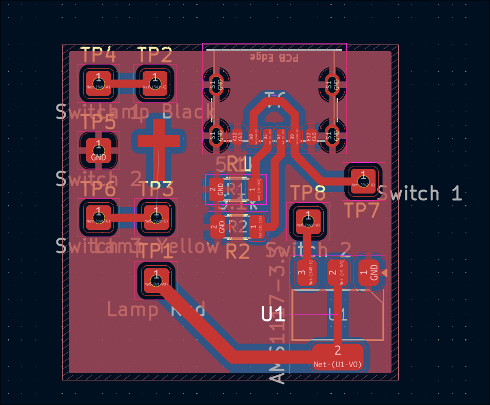
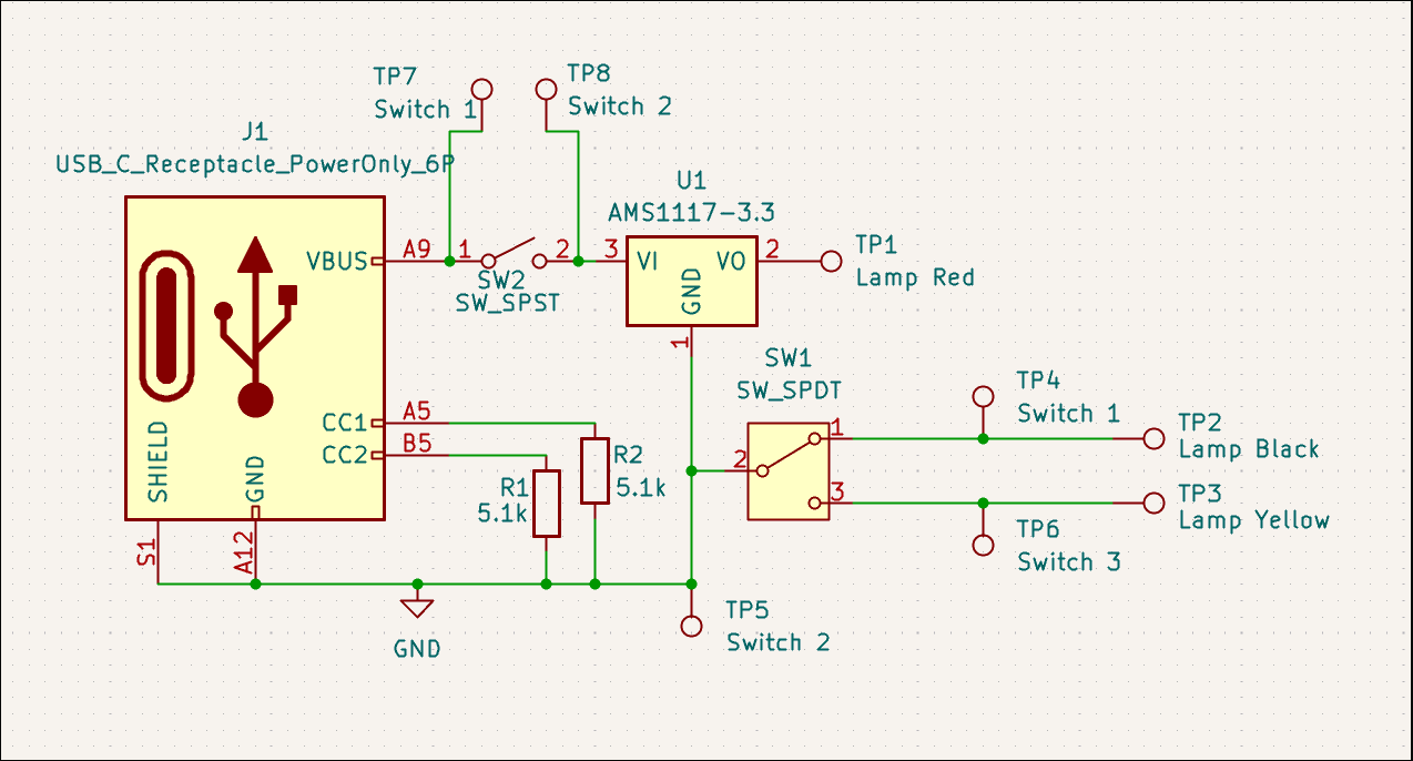
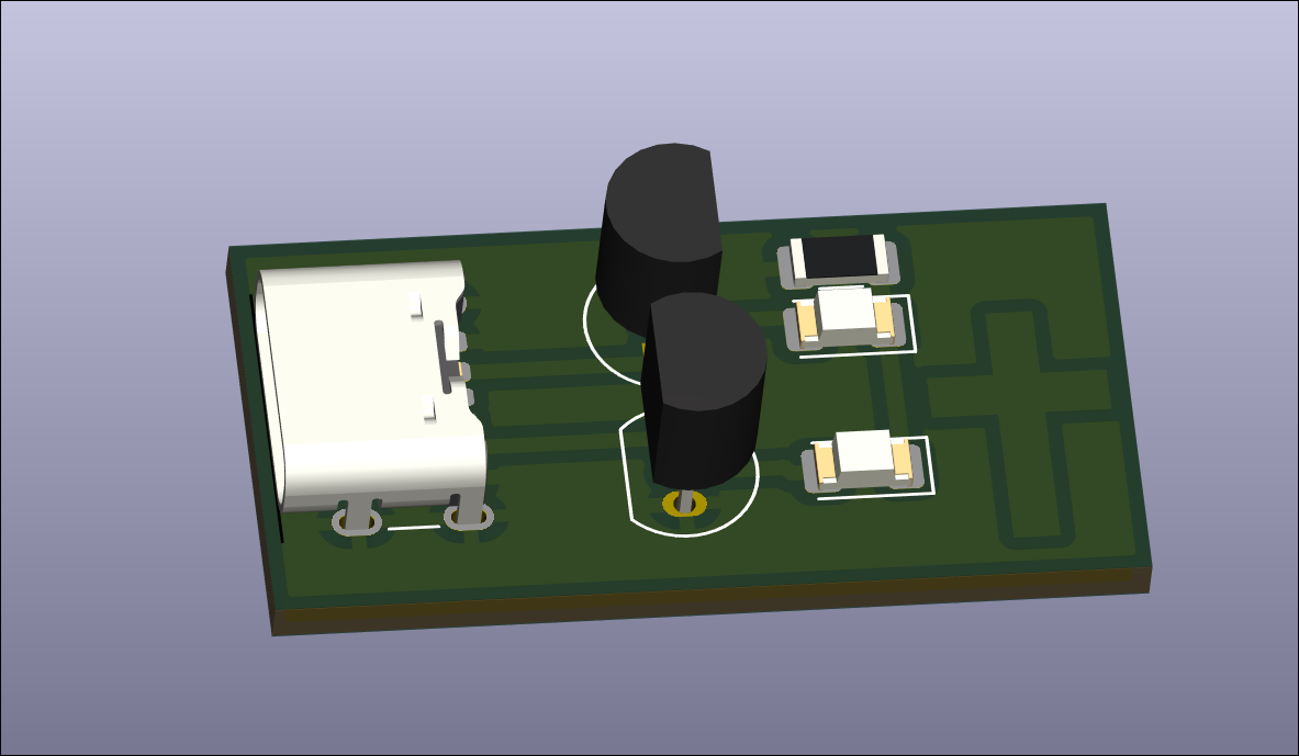
Started first repair/salvage effort for a USB power strip/lamp. The issue was identified to be a shot diode and power IC, which will not be replaced due to prohibitive cost. Instead, the lamp will be salvaged. A board was designed to provide ~3V from USB-C with some toggle switches to control the lamp color and turn on/off the light. All the wires will be soldered to the board at the test points. 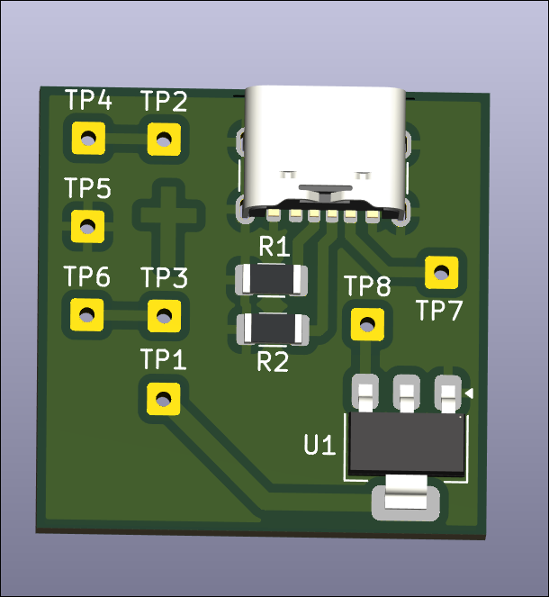
Designed battery-powered continuity checker board (02005-003). 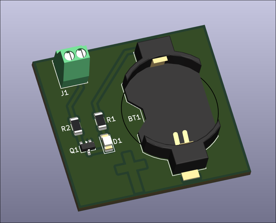
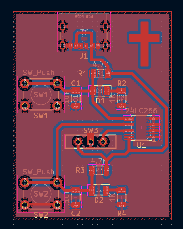
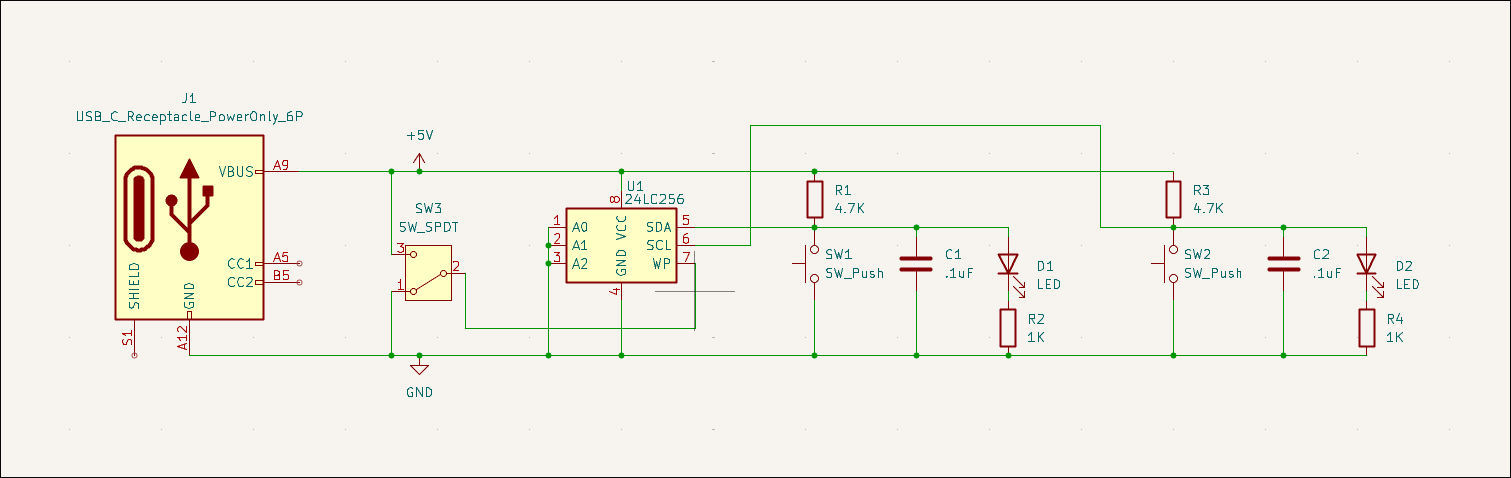
Designed manually read/writable SOIC-8 EEPROM test board (02005-002). 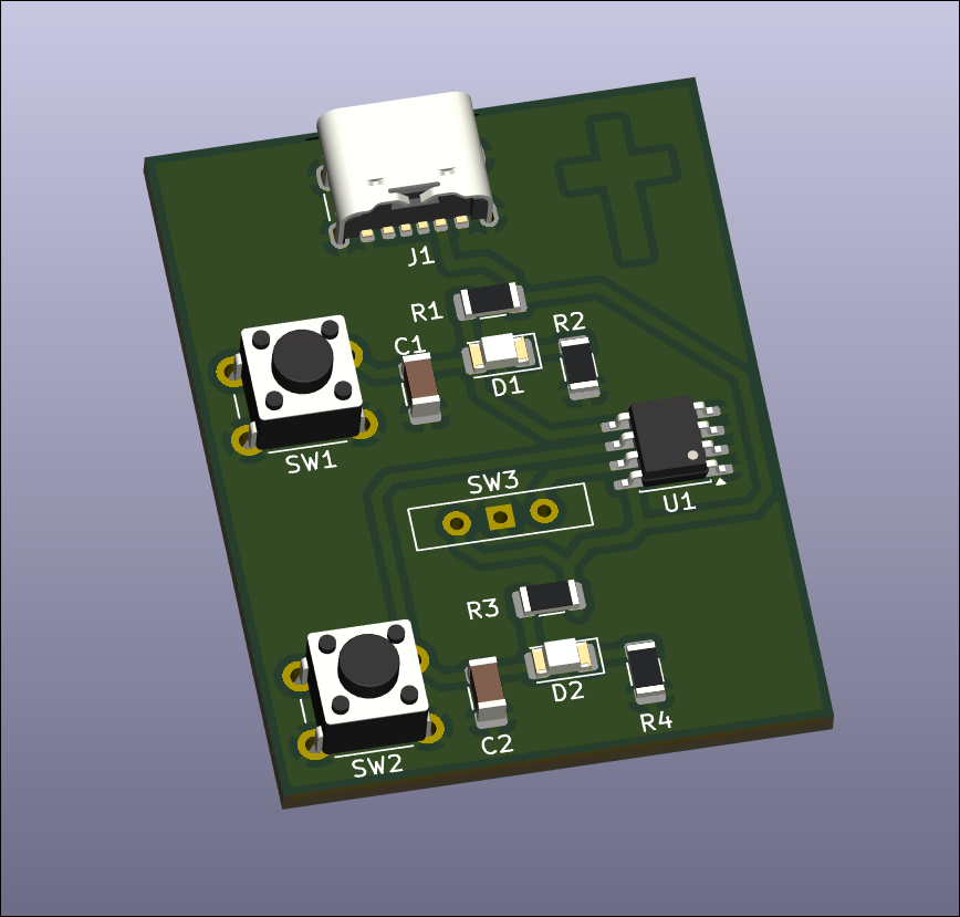
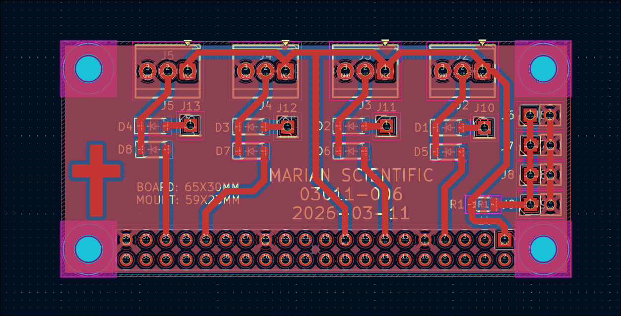
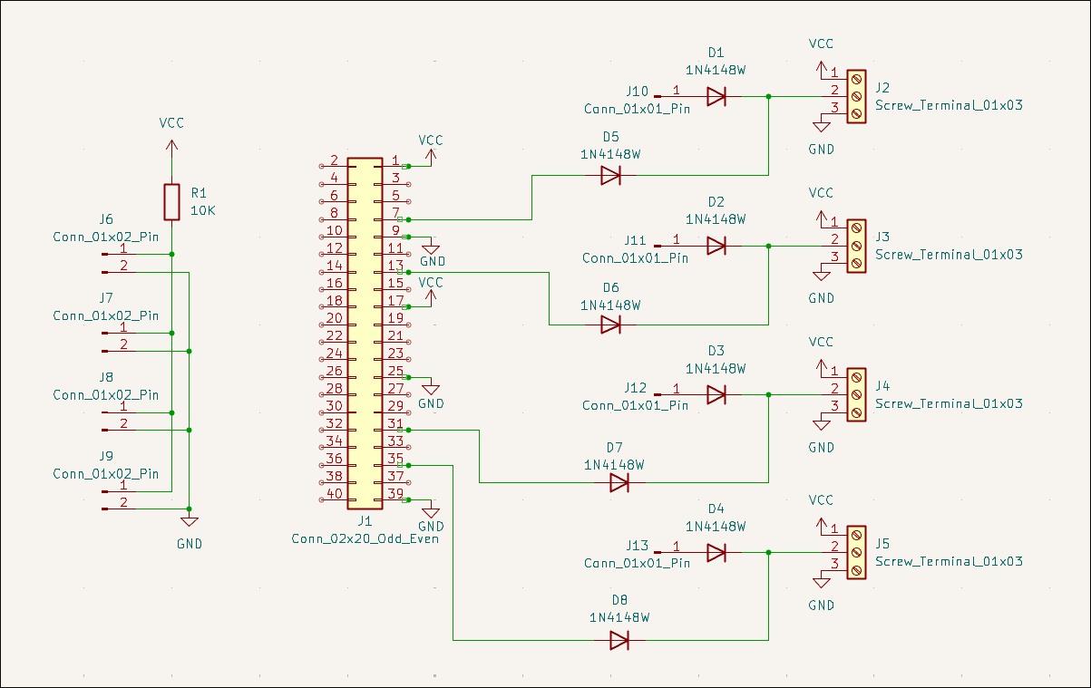
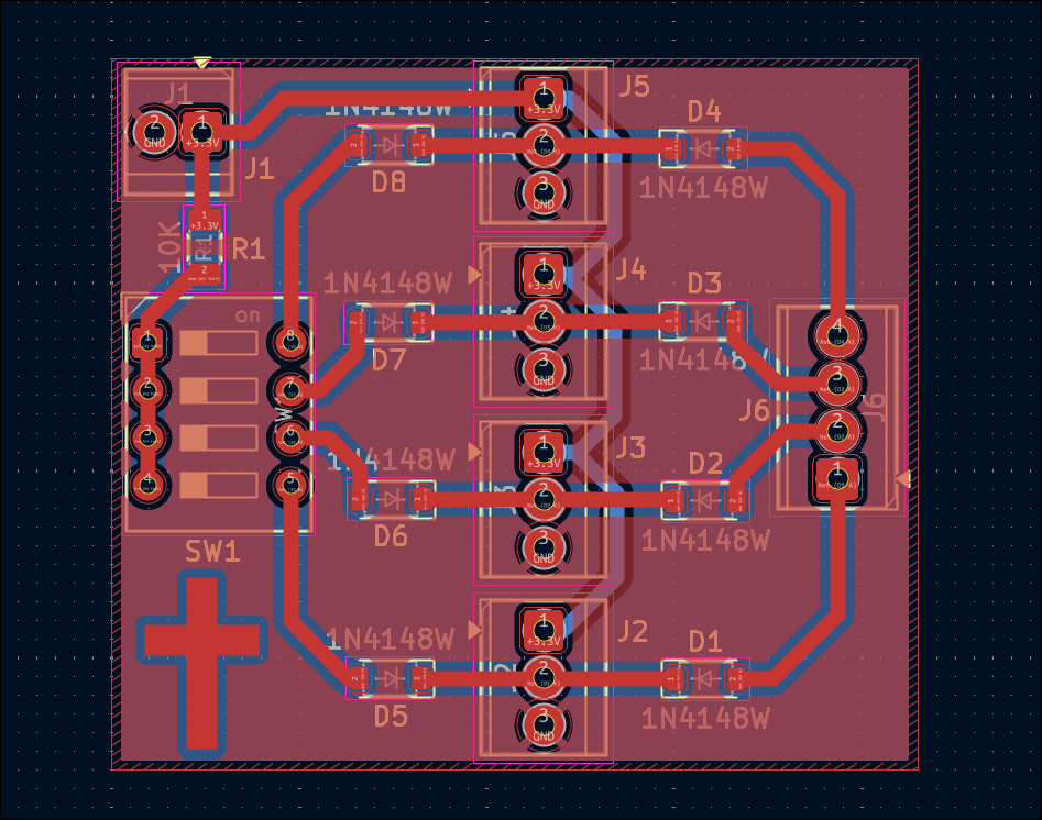
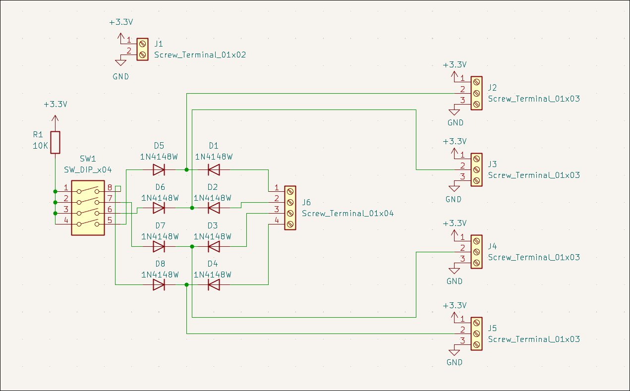
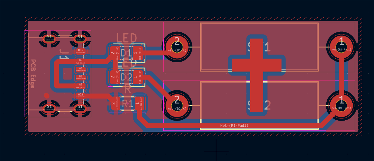
Designed diode ROM 7-segment output board. Did not order at this time due to prohibitive cost ($58/3). 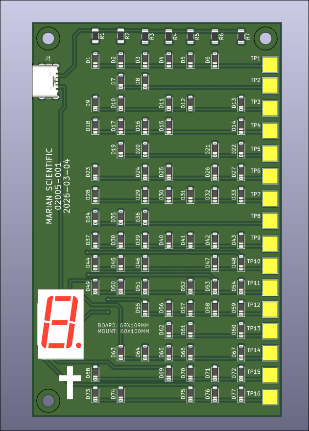
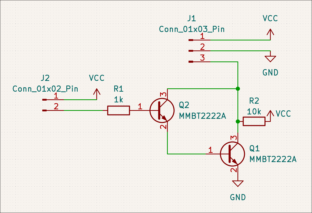
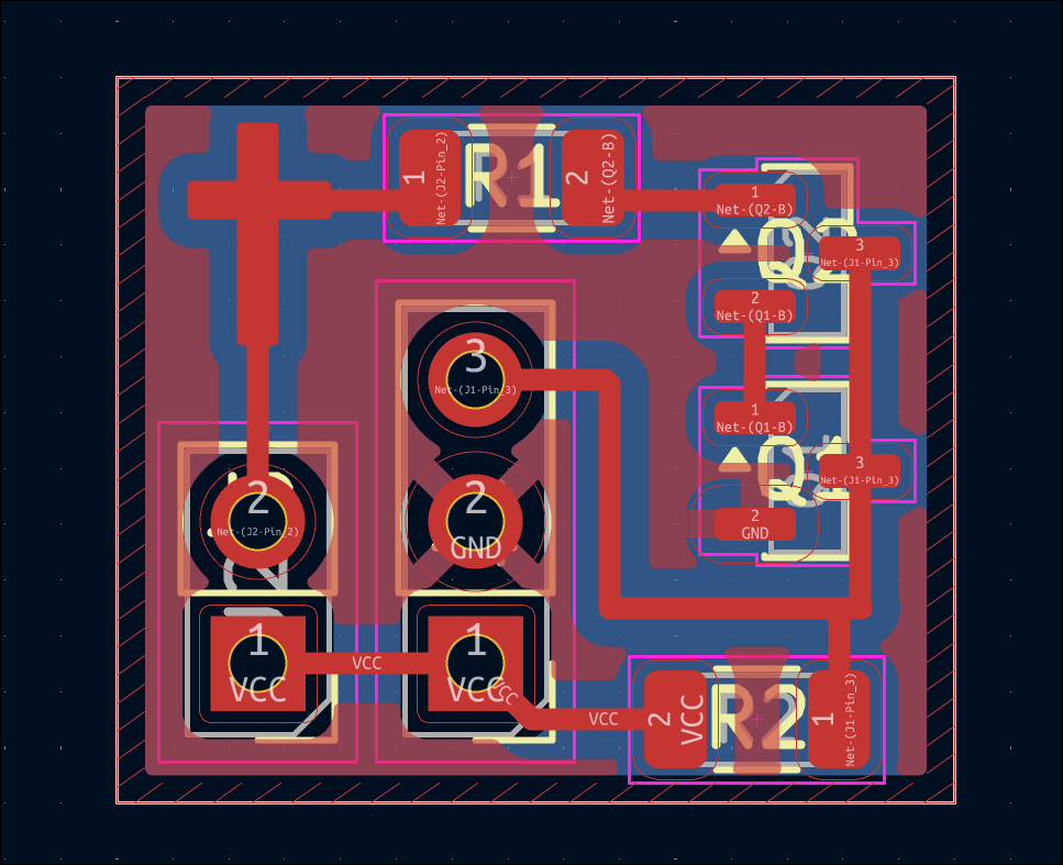
Designed Hall Effect magnetic switch test circuit for future magnet-controlled input sensitivity evaluations. 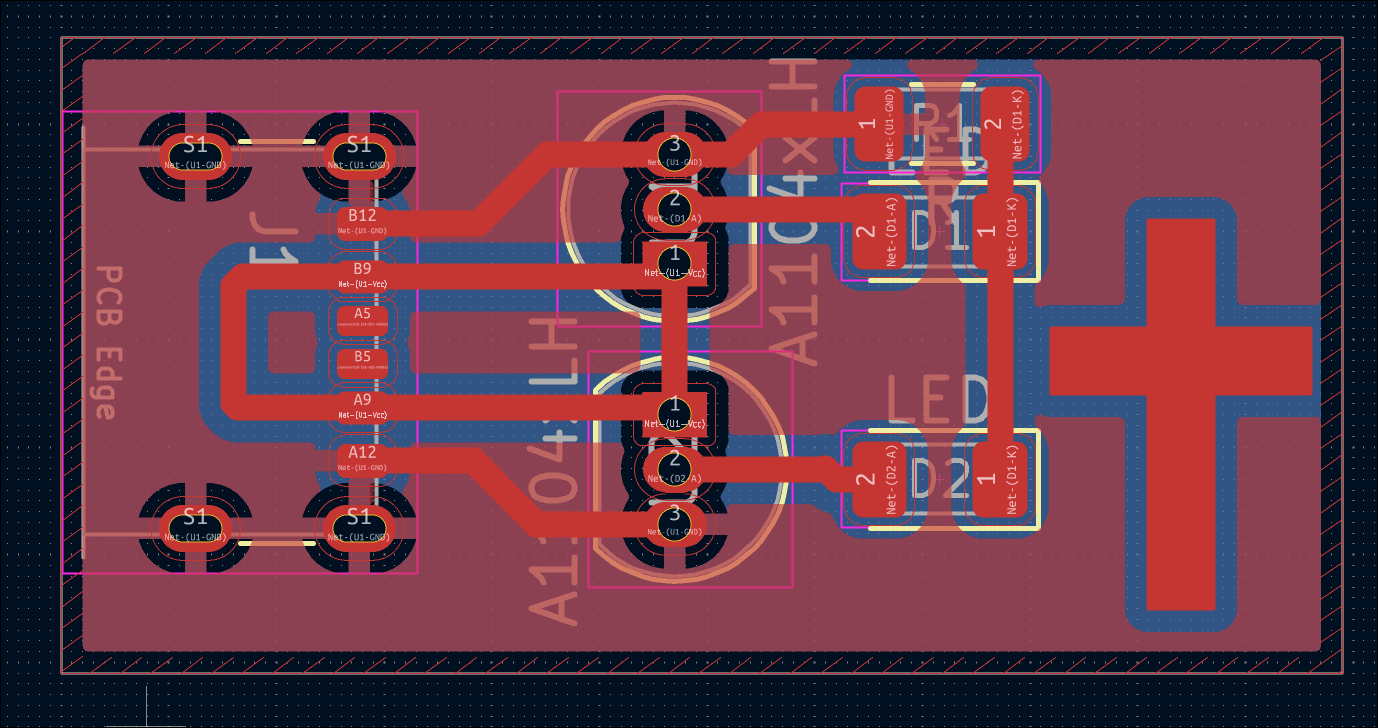
Designed reed switch test circuit for future magnet-controlled input sensitivity evaluations. 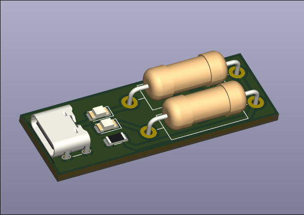
Completed 03007-007 stepper driver PCB design. 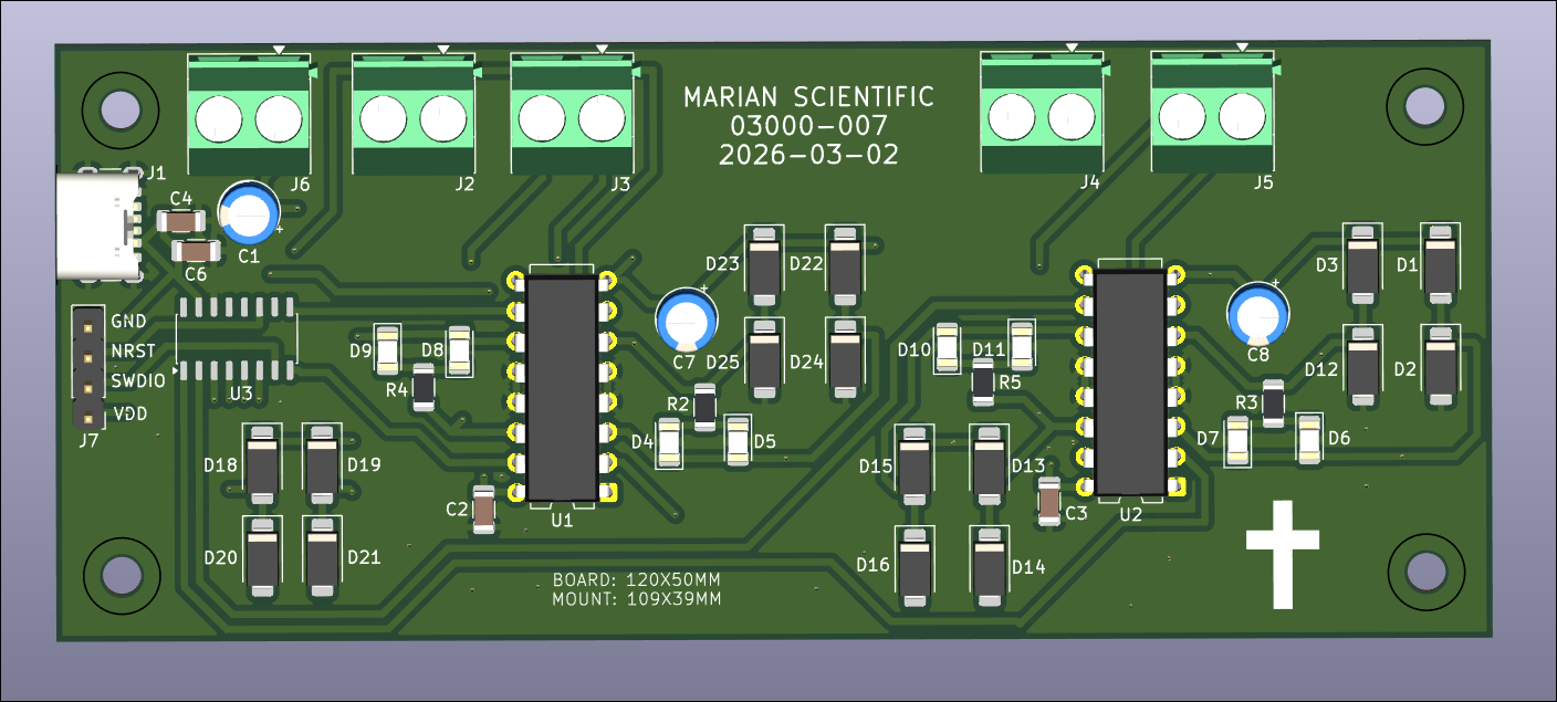
Continued to work on motor driver 03007-007 board. Got roughly 2/3 of the components placed. Will check the circuit and place the rest tomorrow. 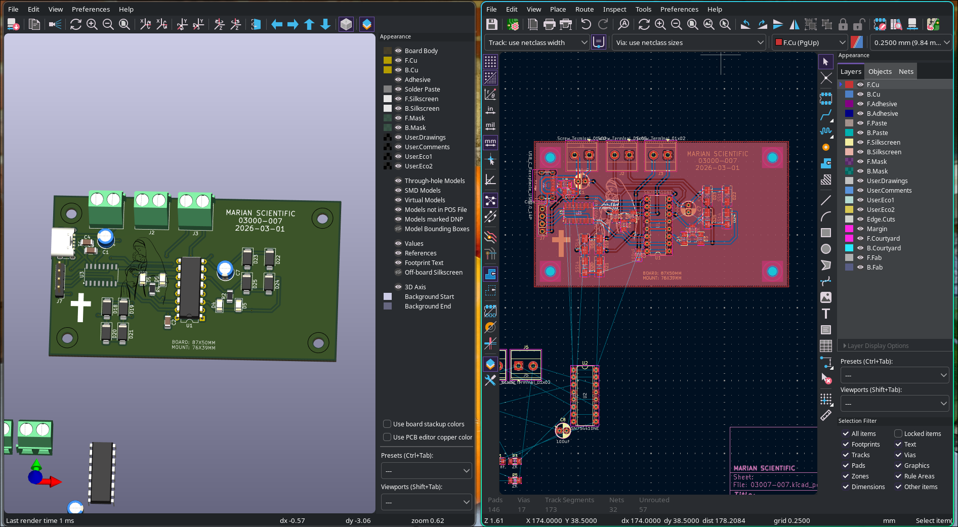
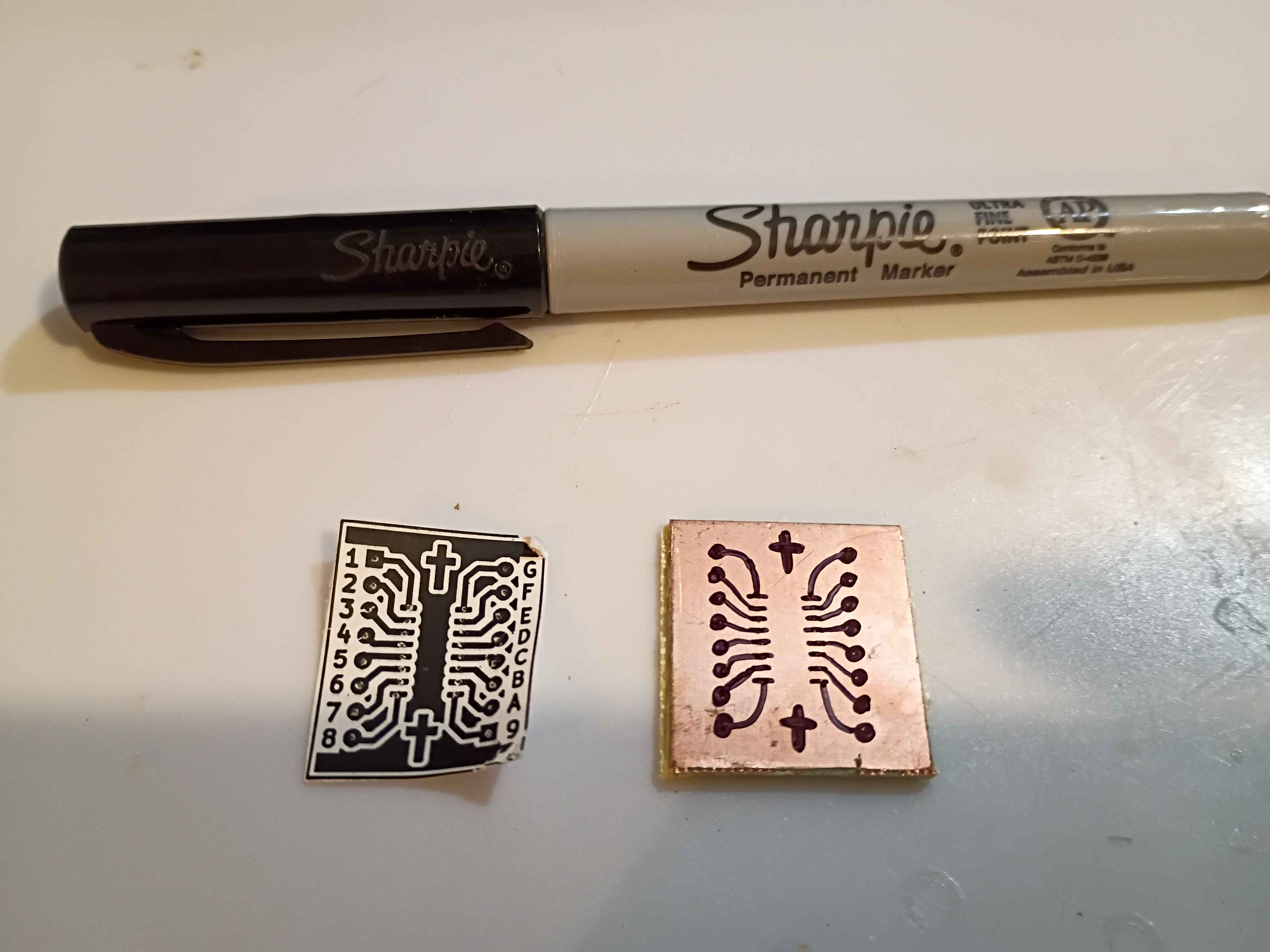
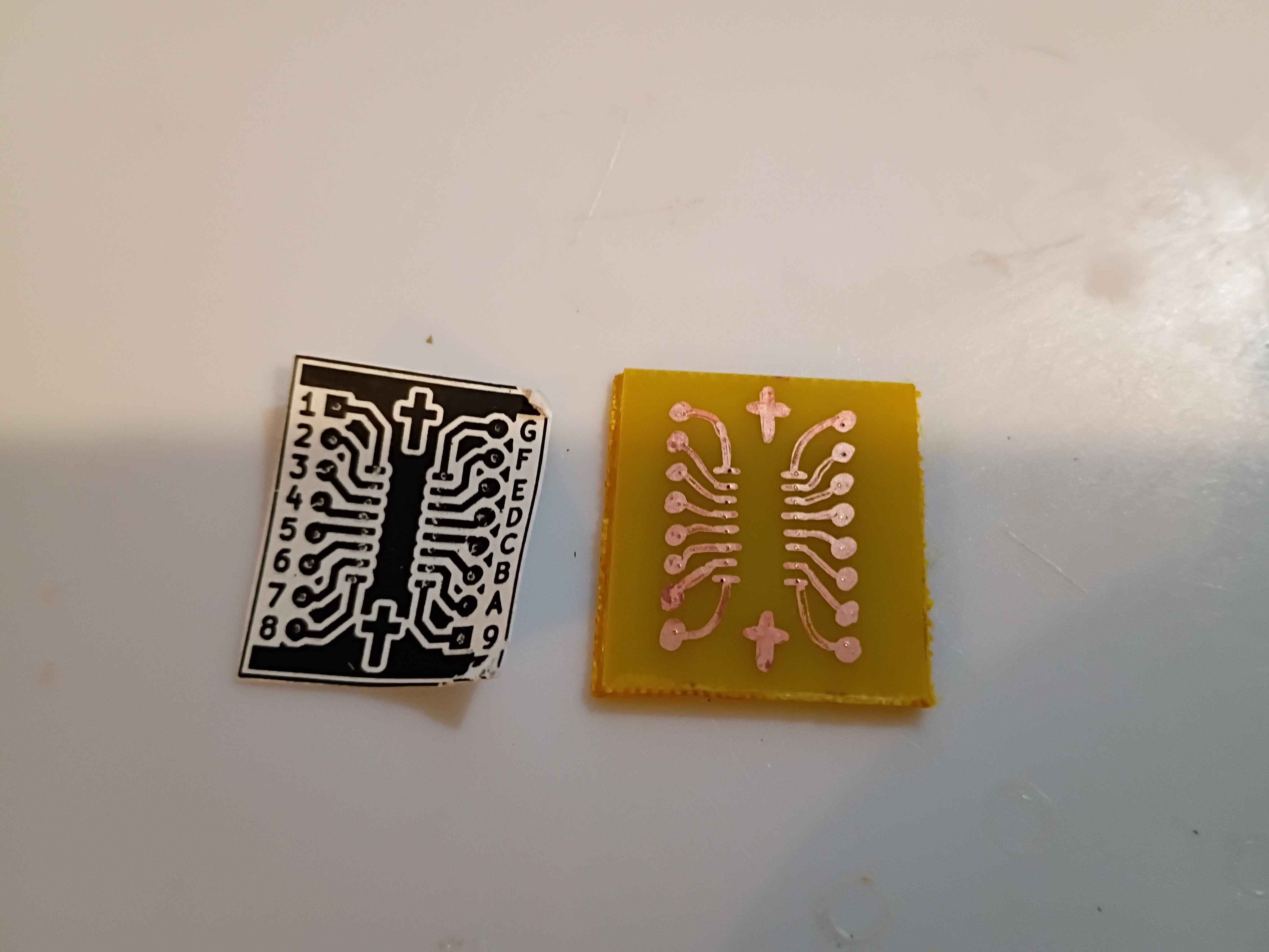
Successfully attempted a new artisanal PCB design transfer method for in-house etching. It involves adhering a non-mirrored image of the traces to the copper face of the copper clad board and pressing in the center of all pads (and corners of all trace line segments) with a thumb tack. Then the paper is removed and the pads and traces are reconstructed by hand using an ultra-fine point sharpie. This has been shown to resist Ferric Chloride etching solution in a previous study. The first attempt was a resounding success, and only took 30 minutes from start to etched board with a very low probability of failure. If the traces are marked incorrectly, they can be wiped away with acetone and easily redrawn. 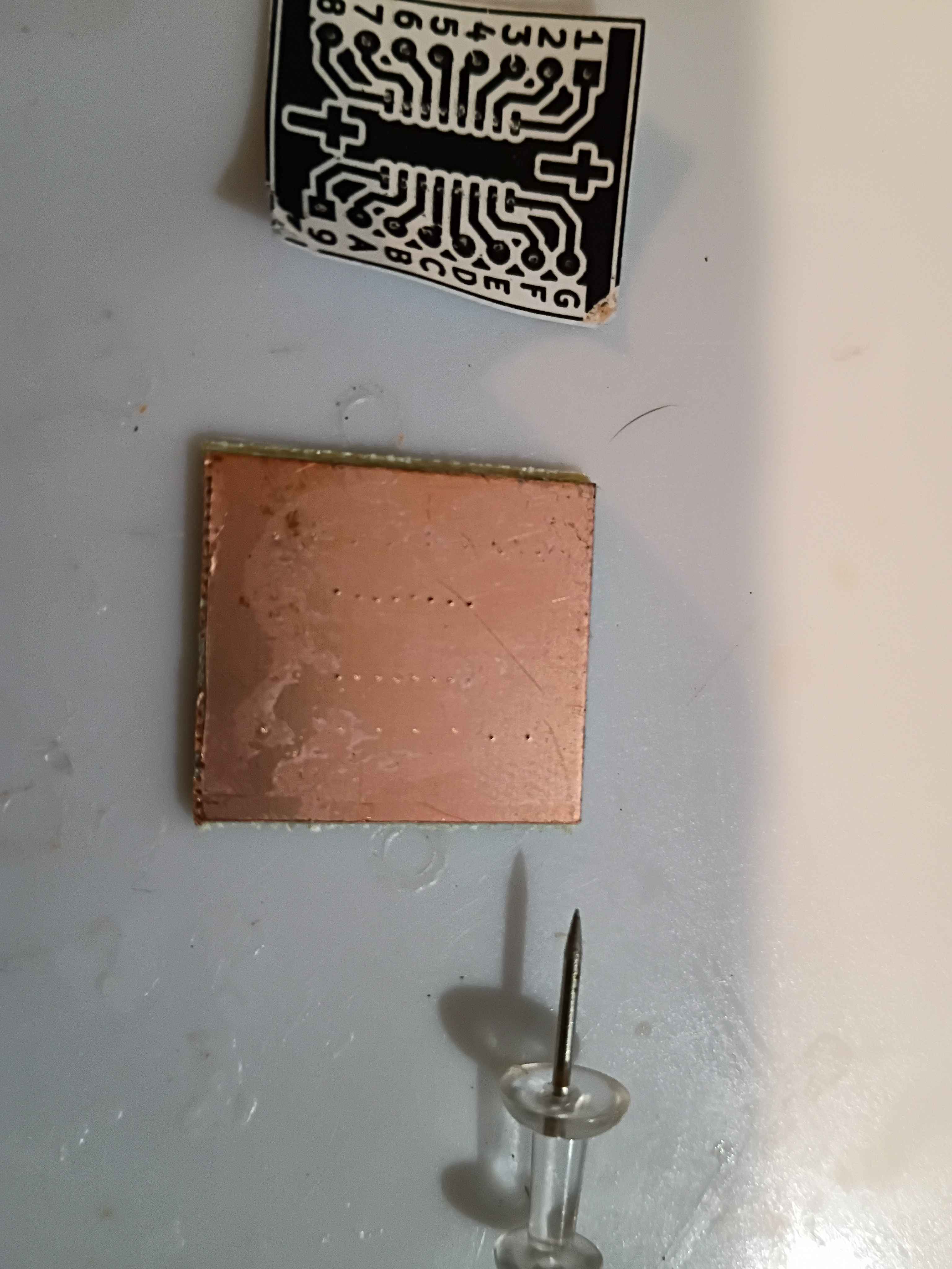
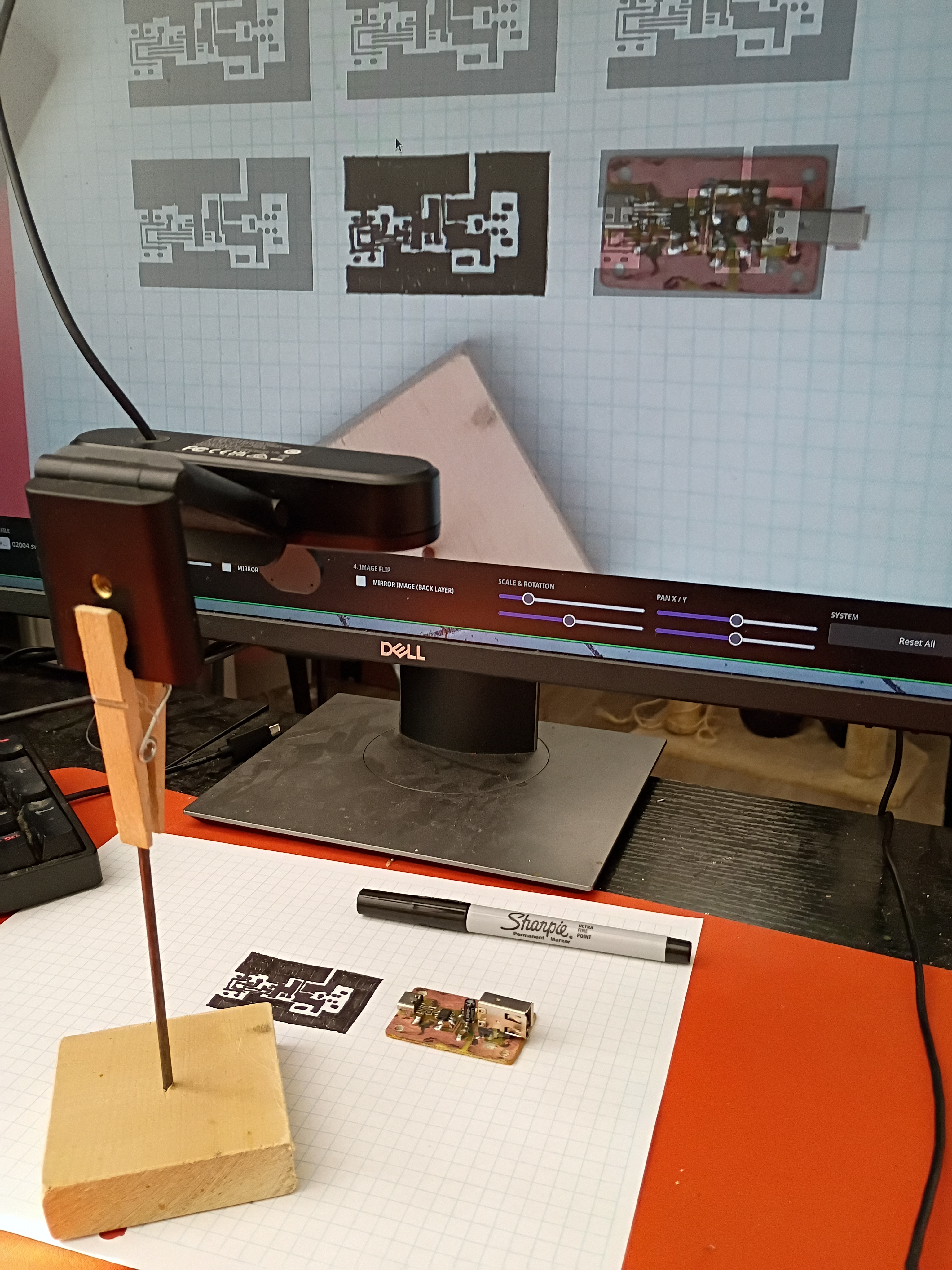
Vibe-coded PCB Camera Lucida utility for PCB tracing. It is available from the http://www.marian-scientific.org/ homepage. It automatically requests the webcam feed and allows the user to upload their mask for tracing. It includes all the basic image transforms at the bottom of the page. It seems to work well. Note that the camera needs to face directly down onto the trace plane, and the user will need to ensure the overlay is scaled properly before starting to trace (maybe put the corner points down and ensure those are spaced appropriately). For the sample trace shown below on graph paper, some of the ink bled between the fine-spaced pads, even with an Ultra Fine Point Sharpie. However, this ink bleeding doesn't happen on a copper surface. 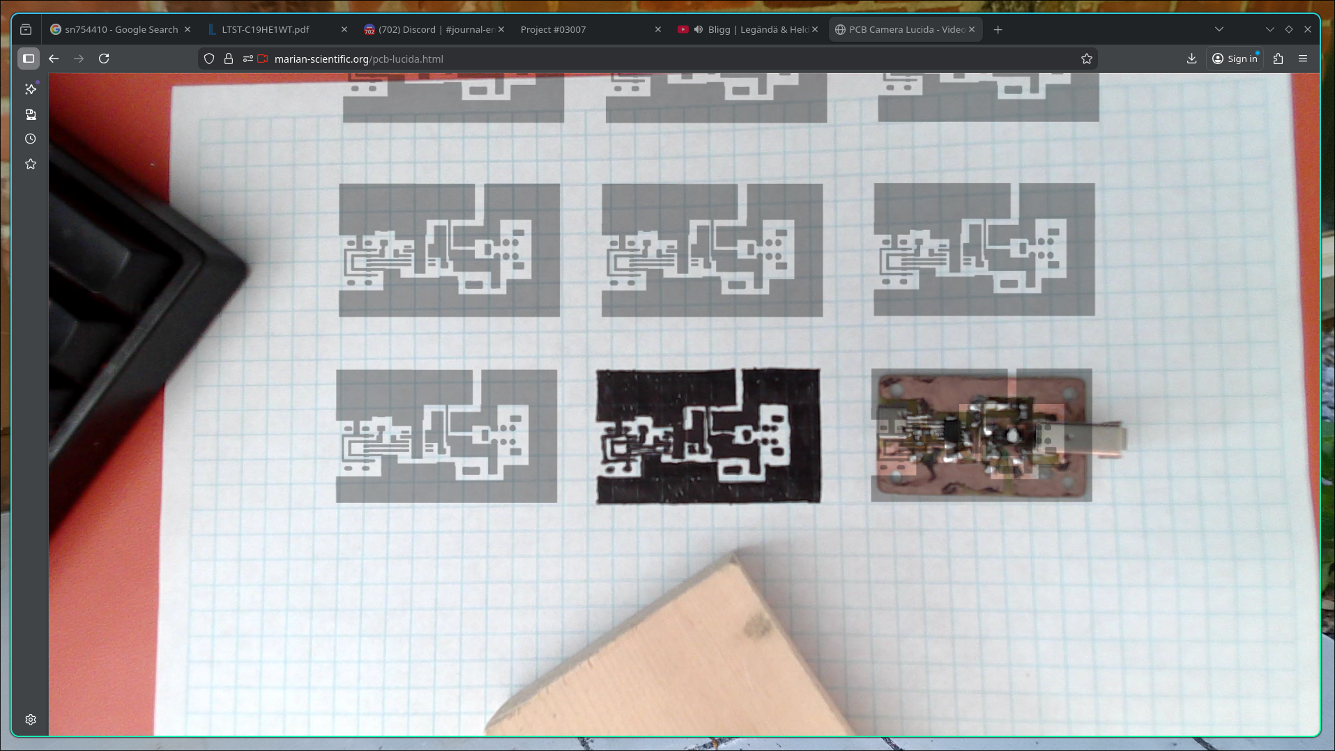
Began schematic design for a CH32V003 stepper motor driver circuit. Still need to add programming header pins to the IC and double-check the circuit.