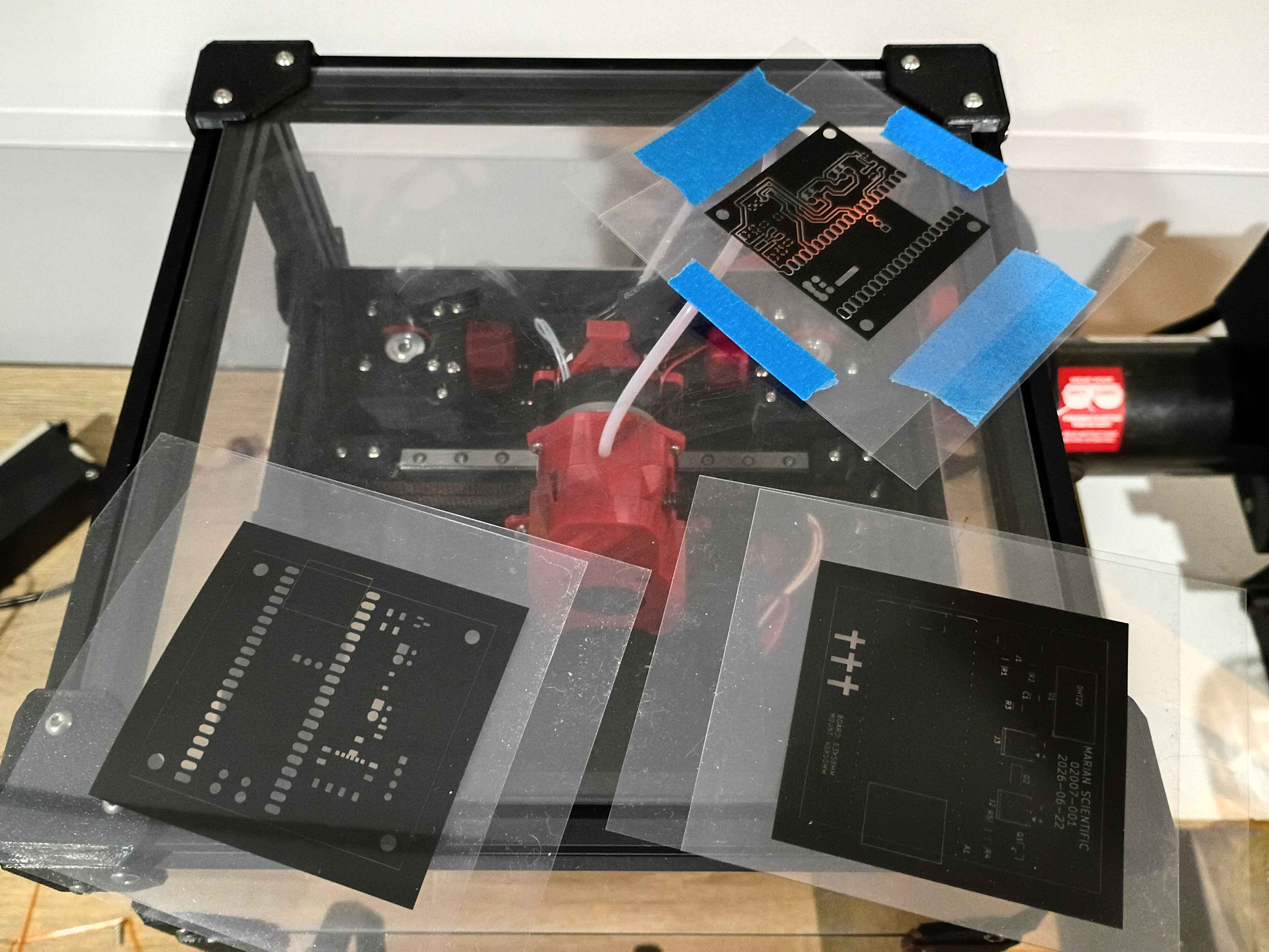
Made slight adjustment to copper traces on PCB design and printed a UV mask. Also made a slight update to the software to hopefully improve TCP connections.
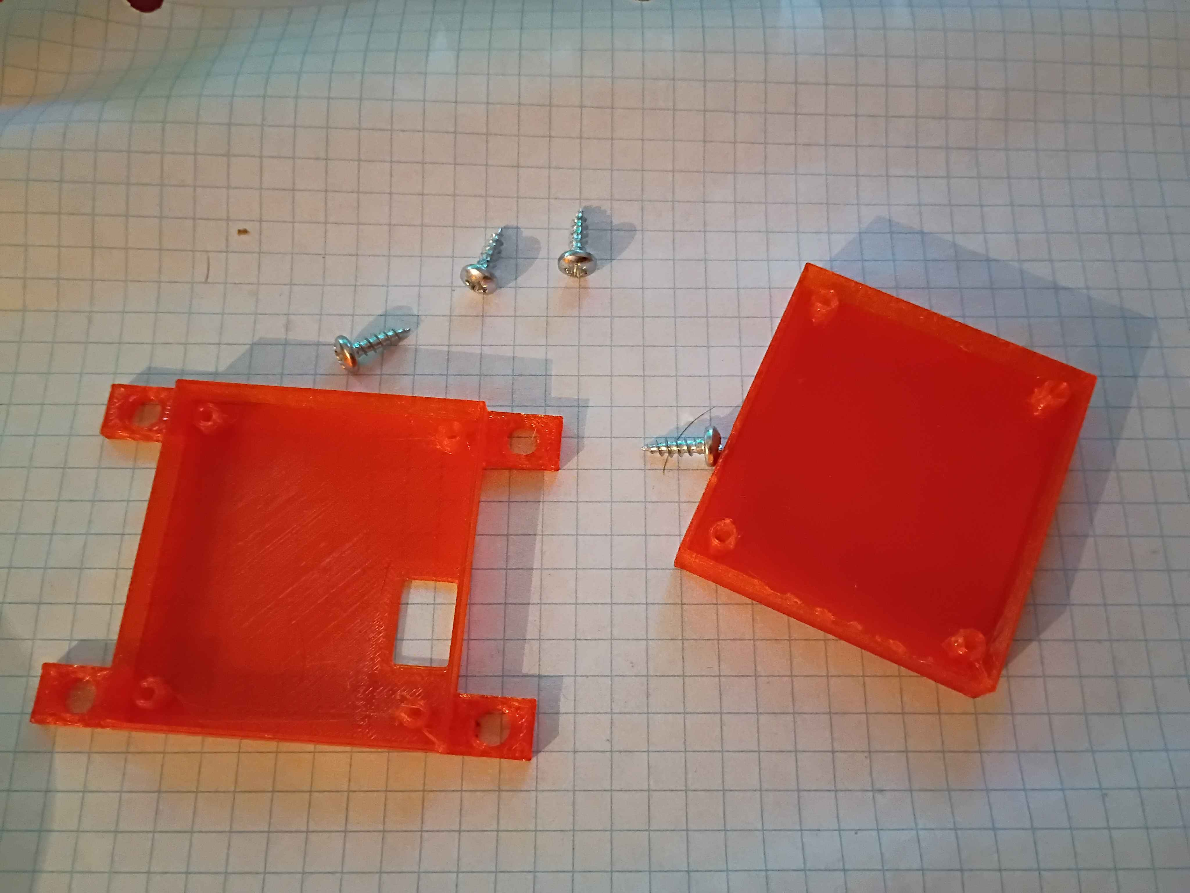
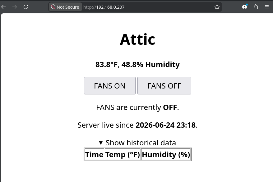
Updated housing model to have flanges to screw into the wall. Printed in translucent orange (best color) PCTG and found 4 perfectly sized screws in my jar. Updated the Pico web server code to show the server start timestamp, hide the historical data by default, and update to the final 30-minute delay in datapoint recording. 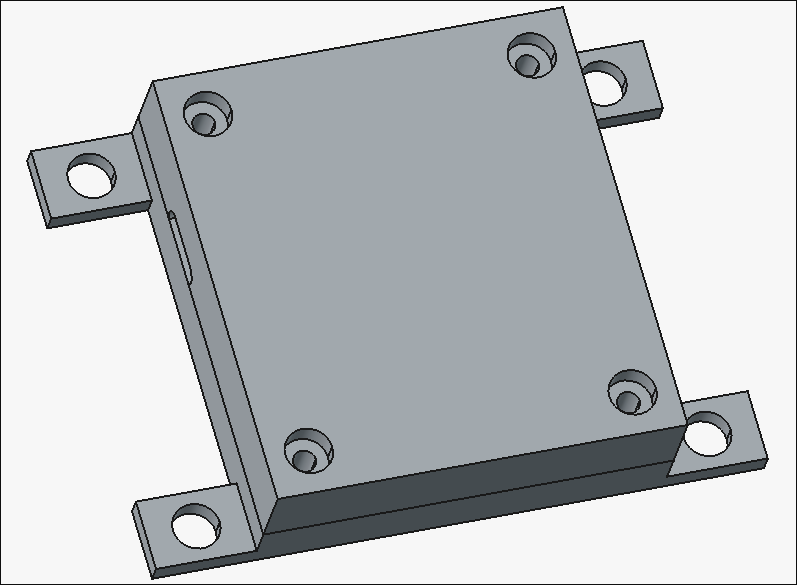
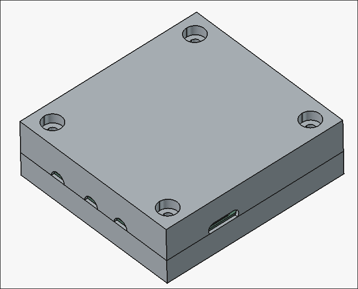
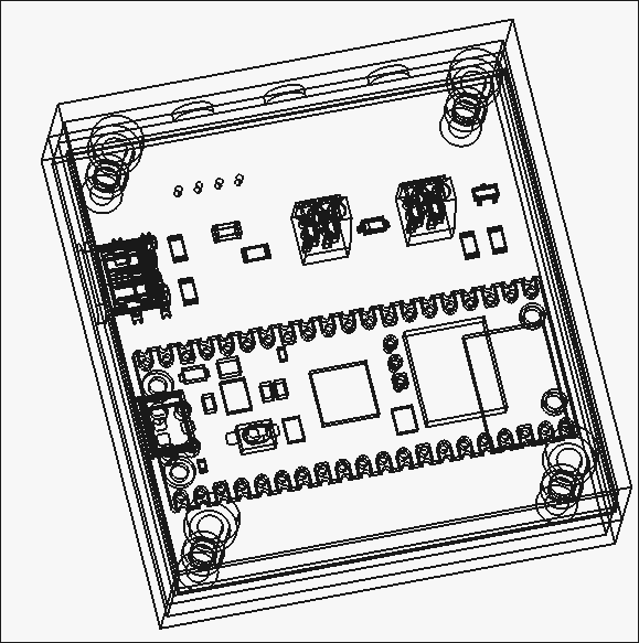
Designed 02007-002 and -003 housing components. There are holes in the box for the antenna (unnecessary), USB-C connector, motor wires, and sensor wires. 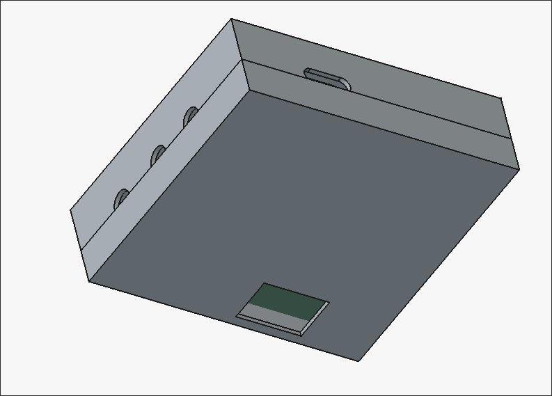
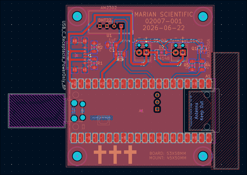
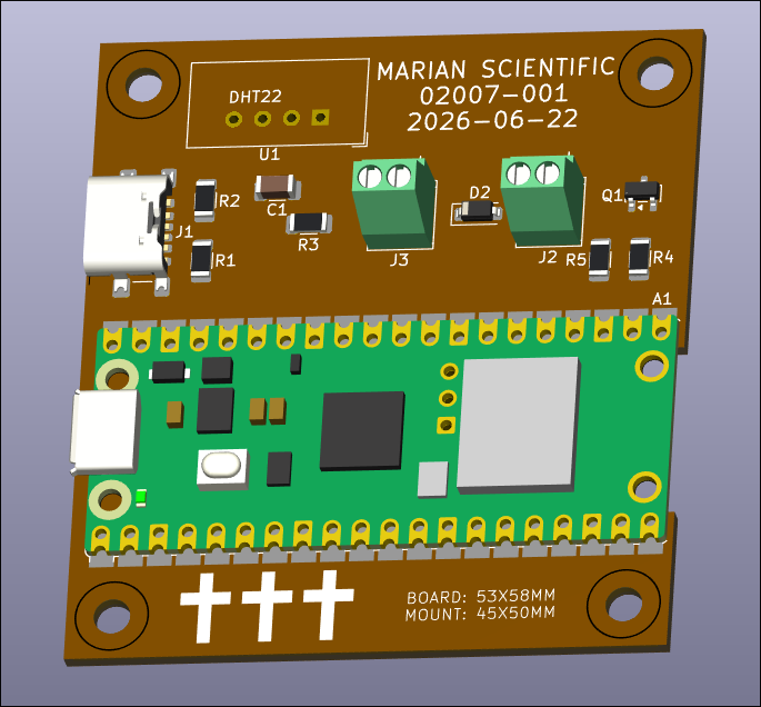
Designed circuit schematic and laid out PCB design for the control unit. 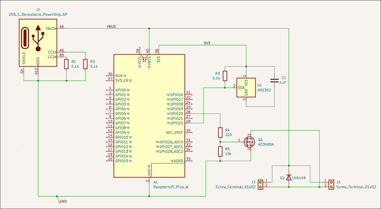
Spent a while getting the connection to the time server working. Attached UI image shows a datapoint every second for testing purposes, but will probably be every ~30 minutes in the live version. 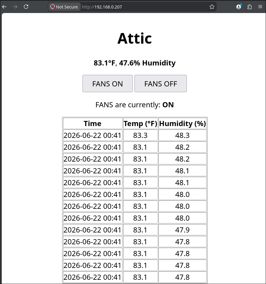
Had to disassemble, repair, and reconstruct the x-axis since the terrible octagonal garbage nut was terrible. Successfully tested afterwards. 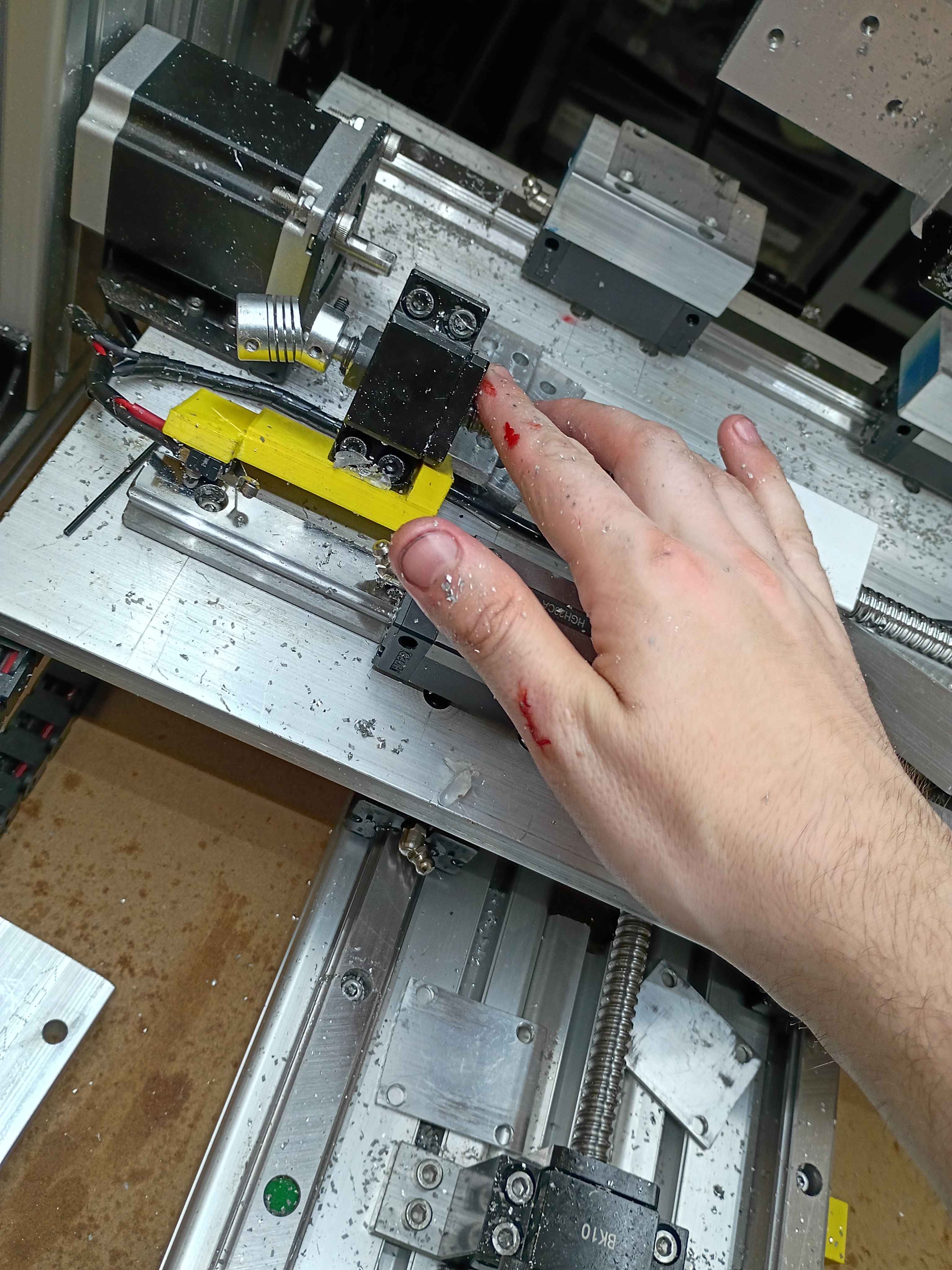
Got the preliminary software mostly working. Ignore the broken UTC date, having some issues with the time server. It allows GPIO control of a Pi Pico 2W thru a webserver, and that will eventually toggle on some small vent fans. It also reports the temperature and humidity. I could eventually add logic that turns on the fan based on the relative temperatures inside versus outside. 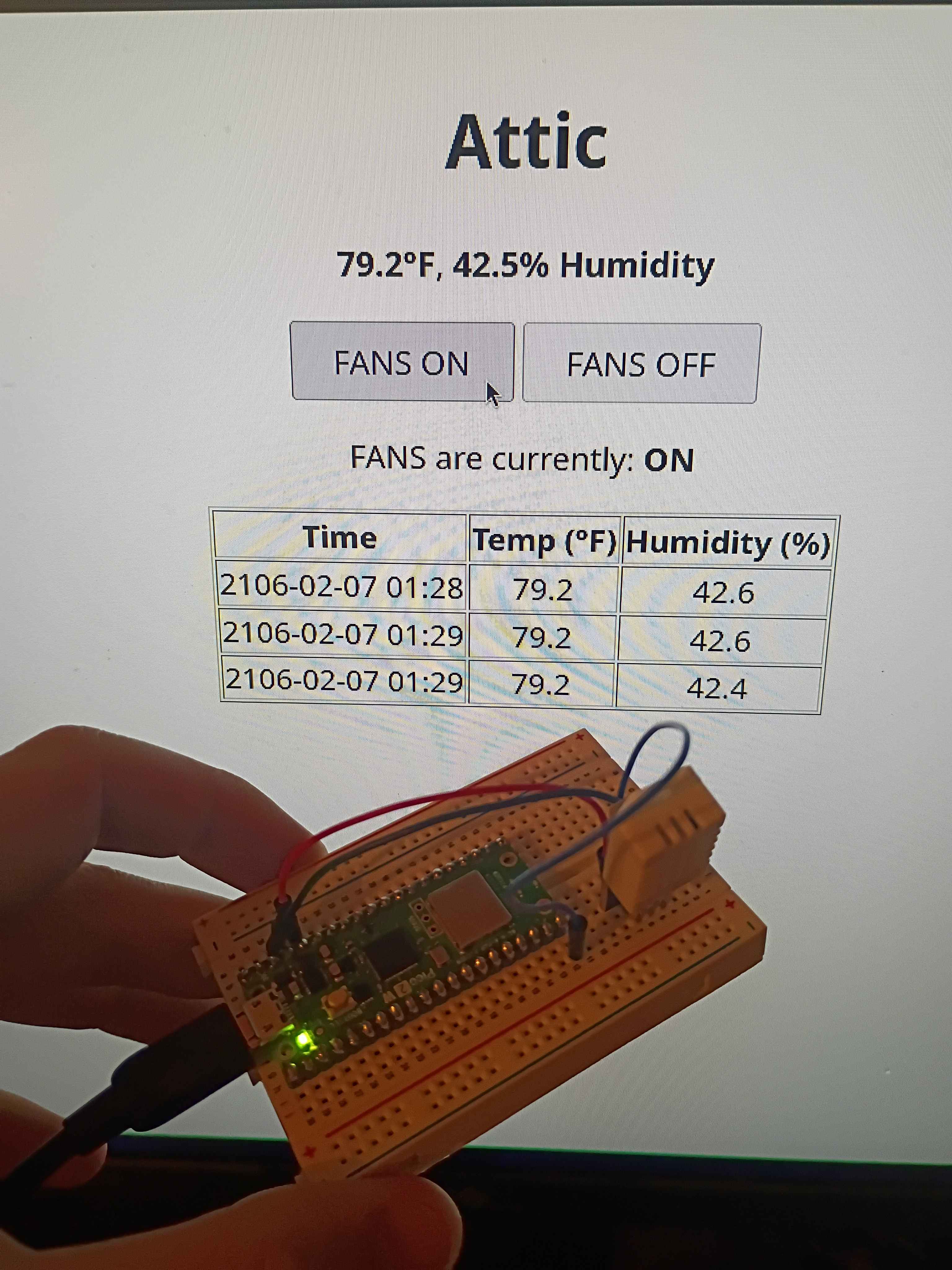
Vibe-coded GPIO control webserver on Pi Pico 2W using the SDK. Will adapt this to control the attic fans this weekend. 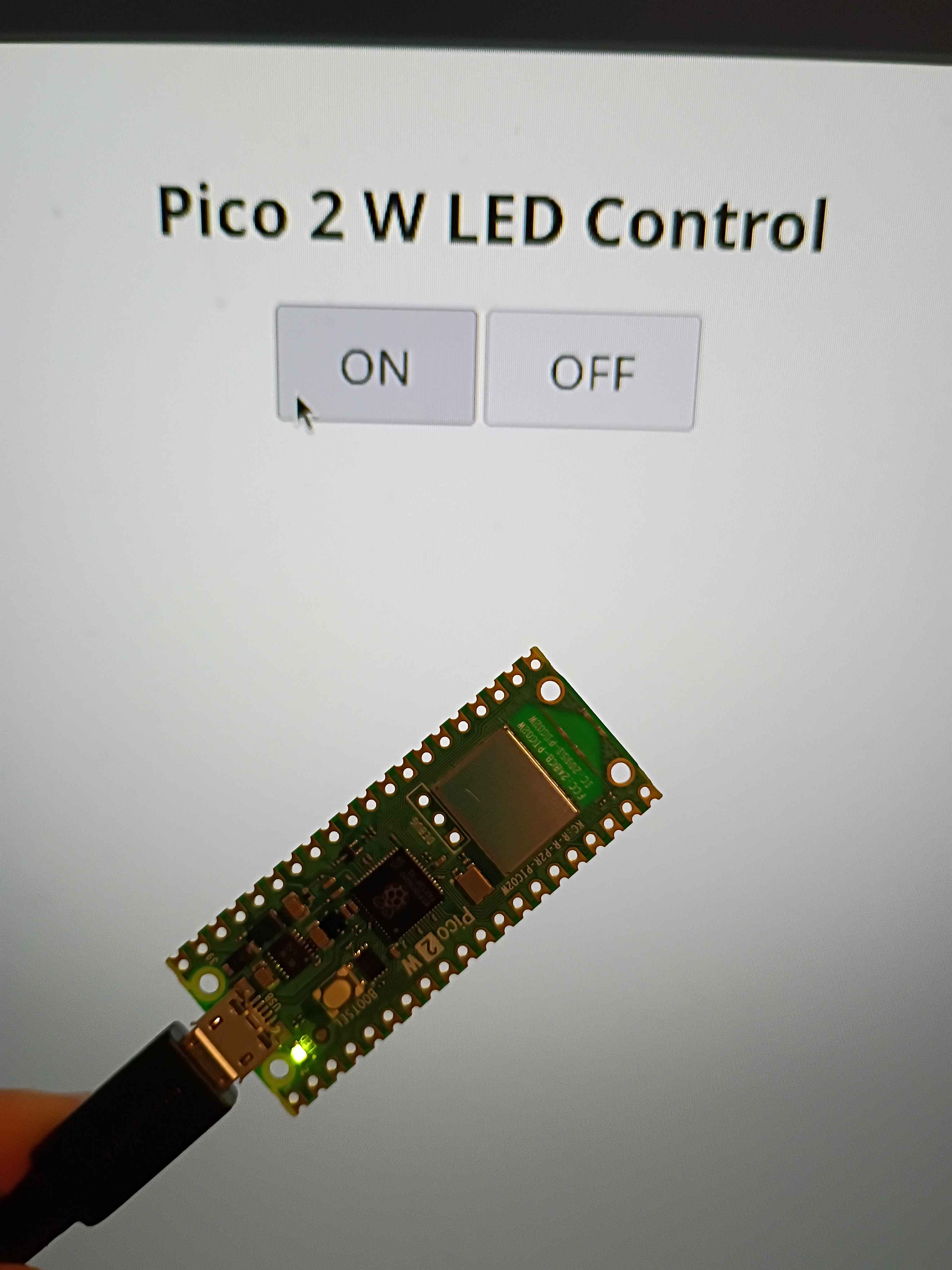
Finished all CAM programming for the 00003-002. Will cut at a time when I am allowed to make some noise. 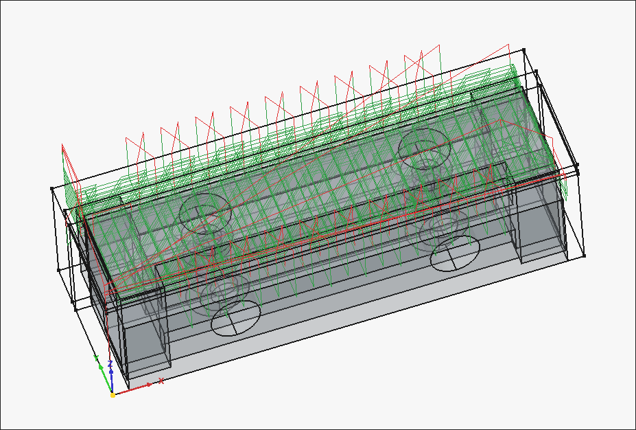
Working CAM paths for the 00003-002. After an hour of trial and failure regarding the "External" slot (on the right side of the image), I discovered that you can do a normal pocket operation by clicking the bottom face of that feature, and then going to "Extensions" and ticking "Enable Extensions" and "Extend Corners". I think the problem stemmed from the fact that the ledge was narrower than the bit diameter, but this cheat code seems to work. 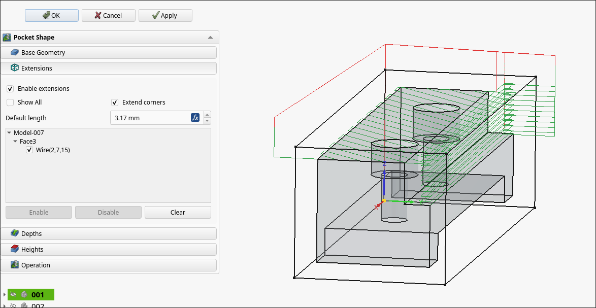
Machined the rest of the 00003-001 on the 00001 CNC prototype. Learned a lot about offsets and the controller. Some lessons learned about the FreeCAD CAM toolbox include oversizing the stock, even in XY if that does not represent the actual material, as this will allow you to be slightly off in zeroing the part, which will save time, since the edge finder takes forever to use. To remove collets from the spindle, after unscrewing, you can choke the collet with one of the wrenches and jam the other one in the gap between it and the spindle and twist, and any stuck collet will pop right off.
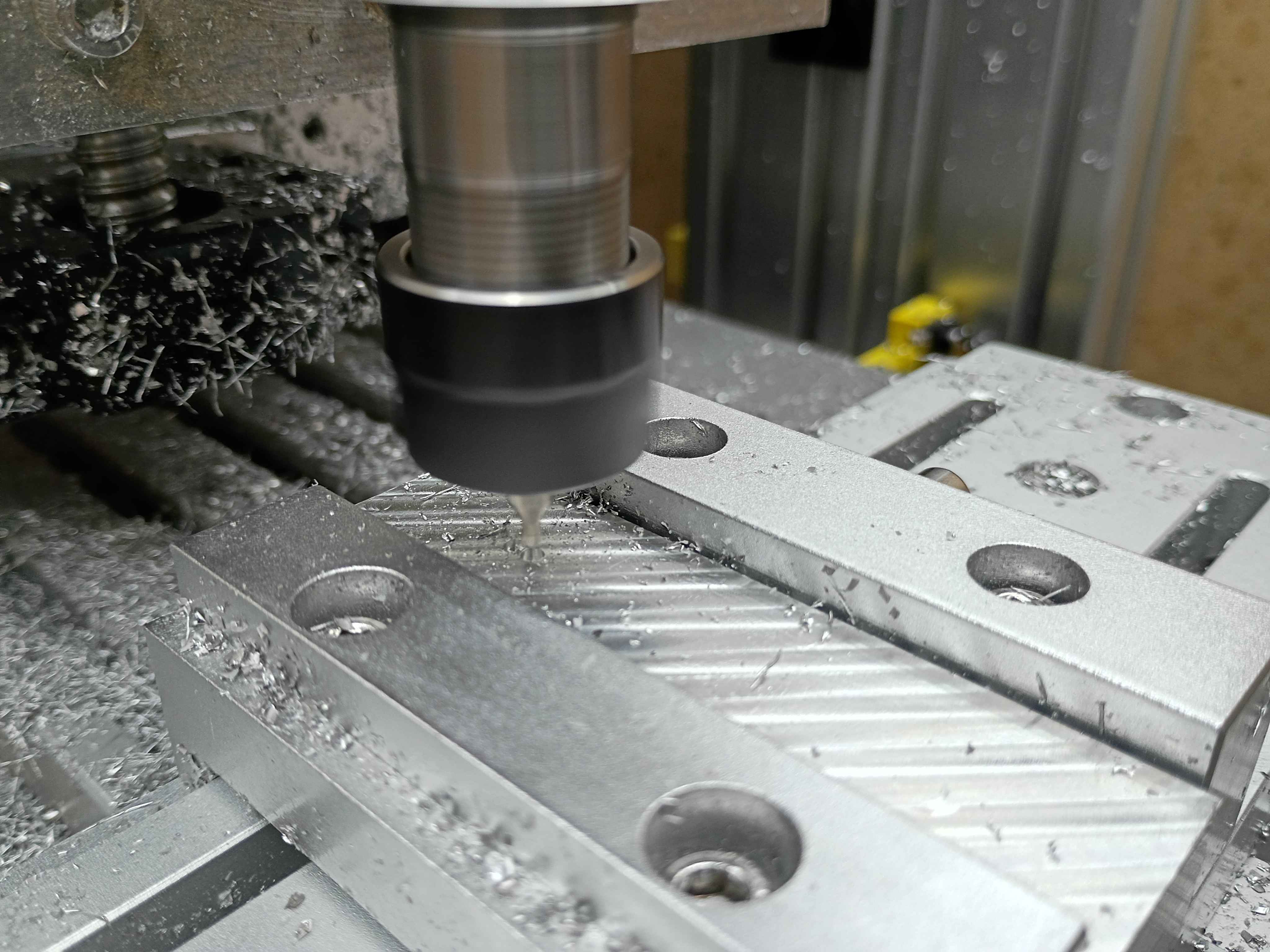
Used the CNC as a manual mill by jogging directly and inputting specific MDI Gcode commands to face certain areas and trim the long direction to size. Also use a tiny center drill on the CNC to precisely position all the holes, though I did drill manually on the drill press and tap by hand.
All in all, took a few hours to make this part, but a lot of that was the learning curve. The other parts are basically copies with some minor simplifications, so I will be sure to time how long those take to produce. 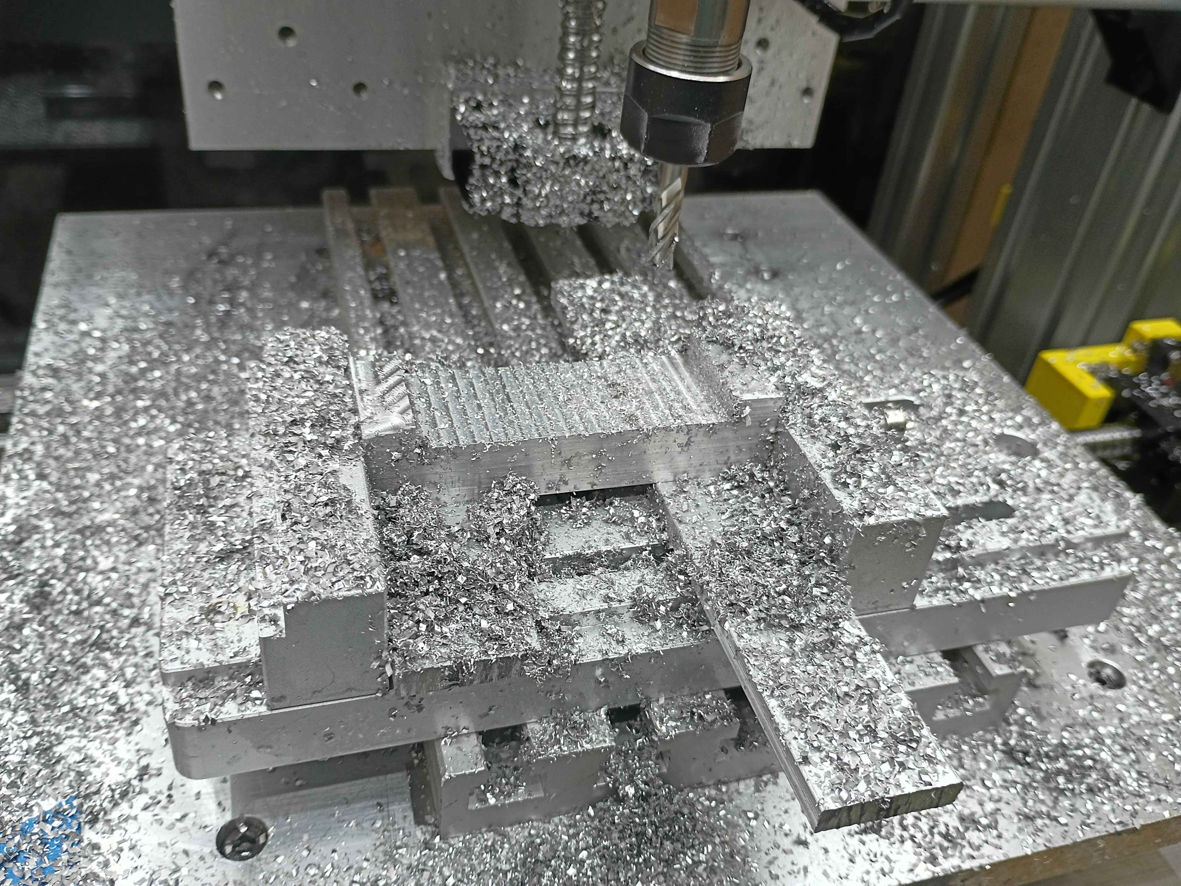
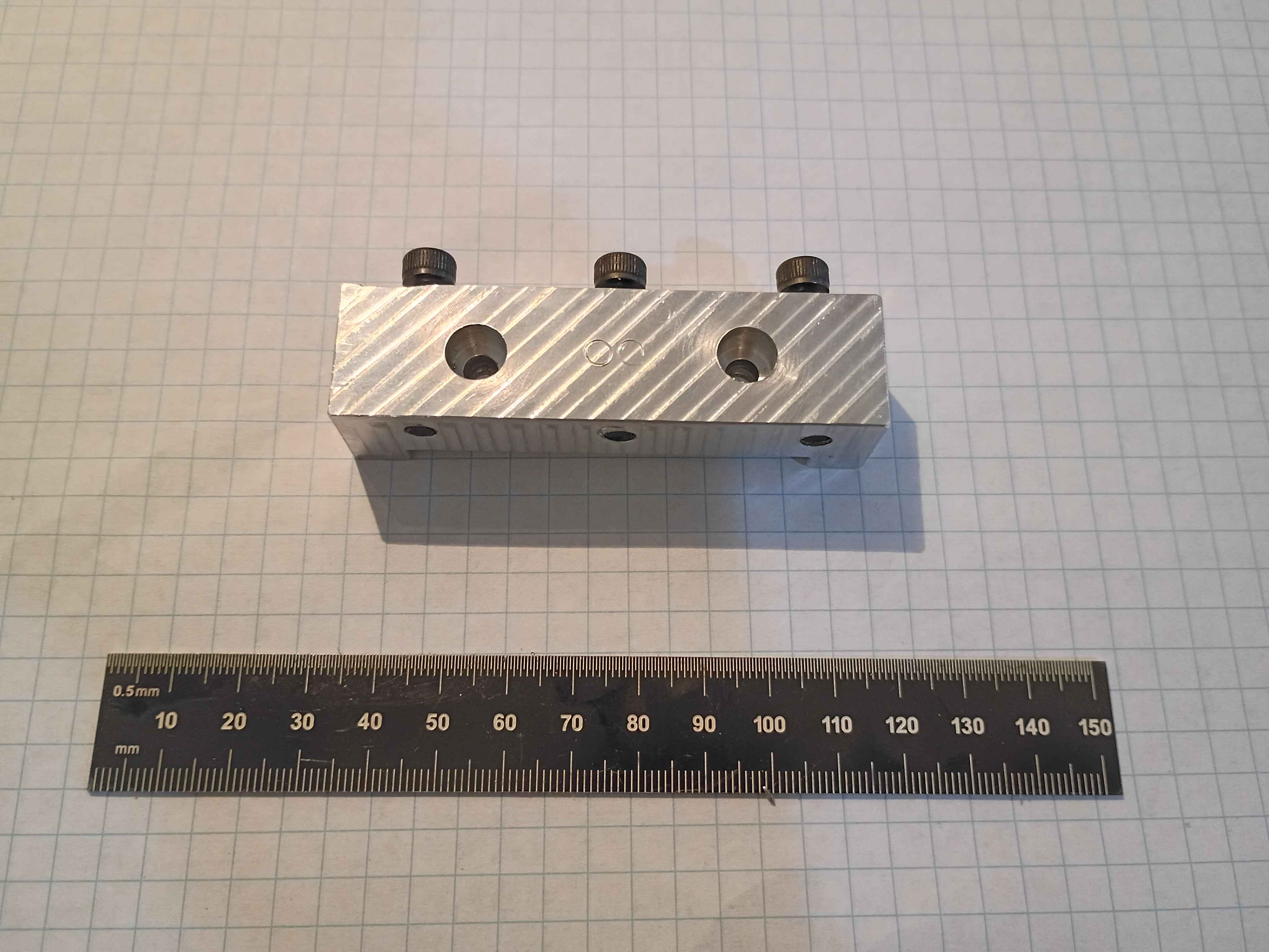
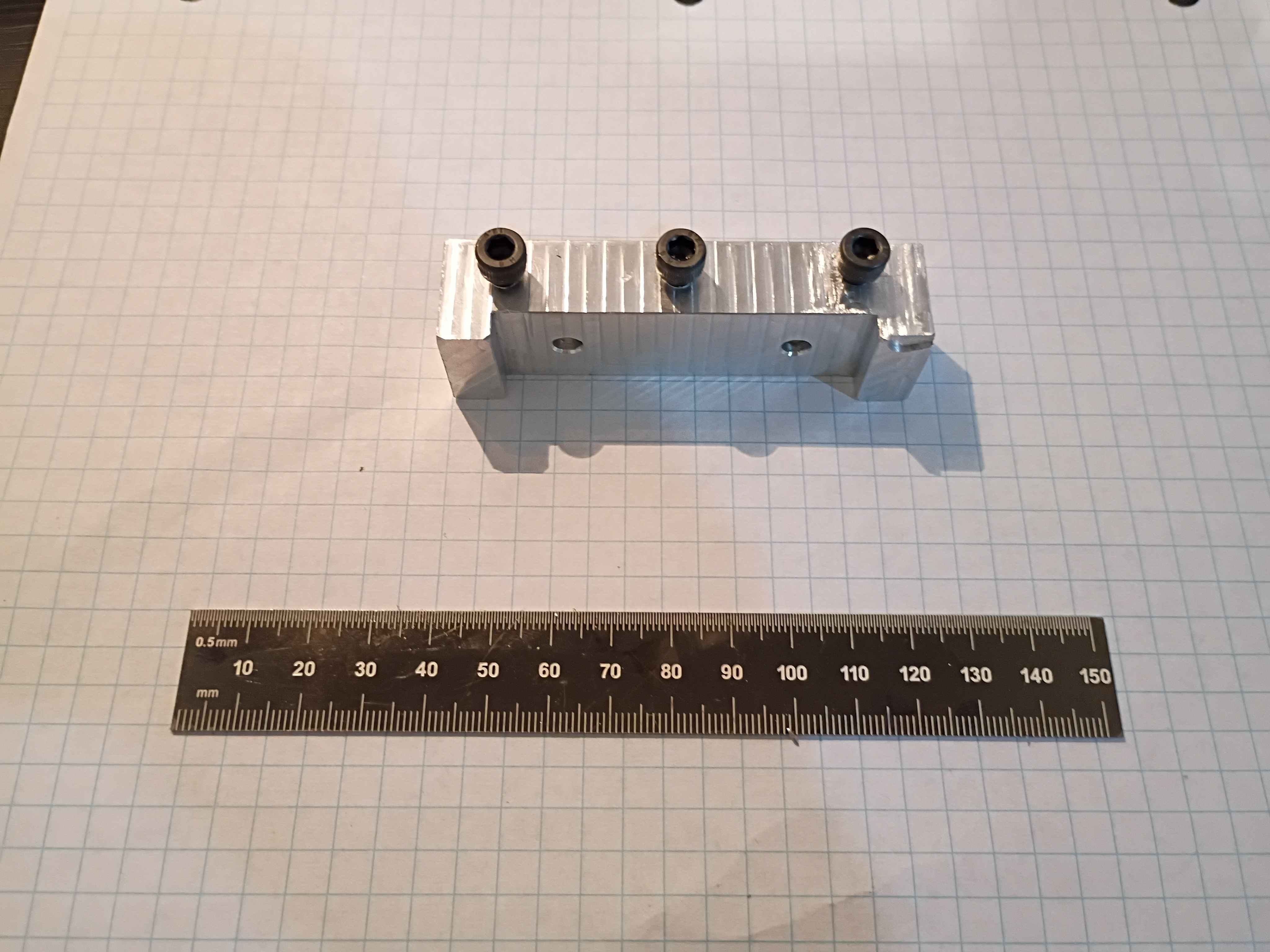
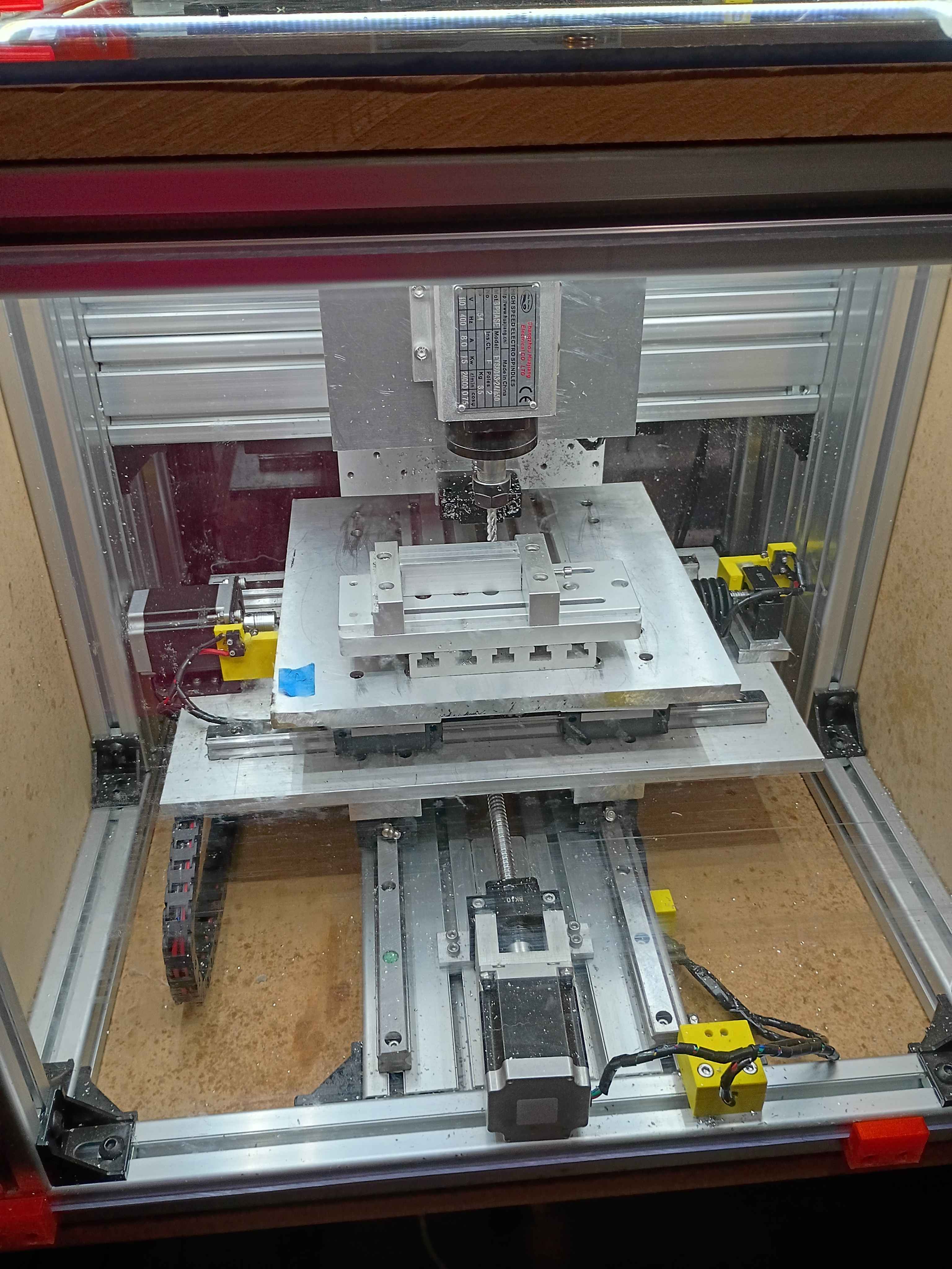
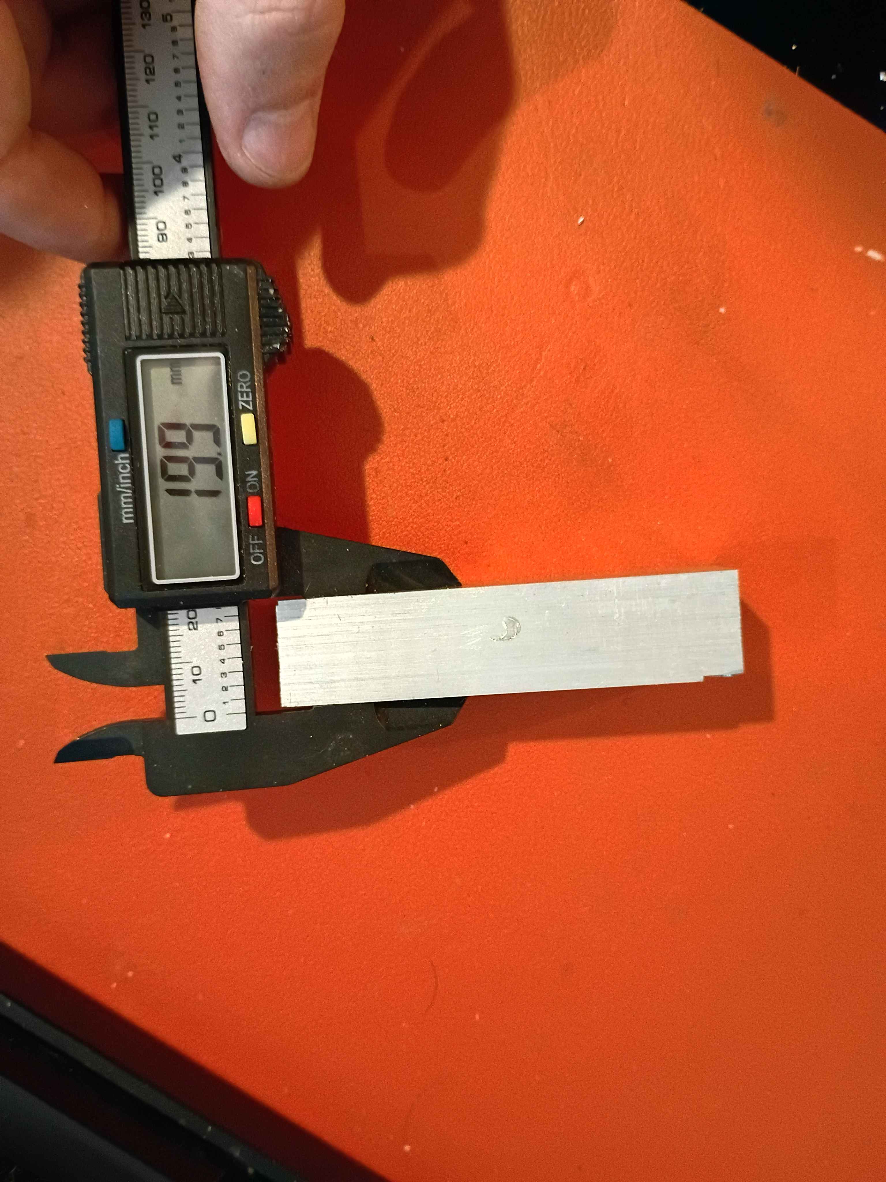
Got some experience with everything from coordinate systems to speeds/feeds, to the Mach3 controller. Faced the top and bottom surfaces to 20mm thickness within .2mm for the 00003-001. Tiny oopsie on the corner (bottom right of second picture), though that should not detract from the function. See video. All good fun. 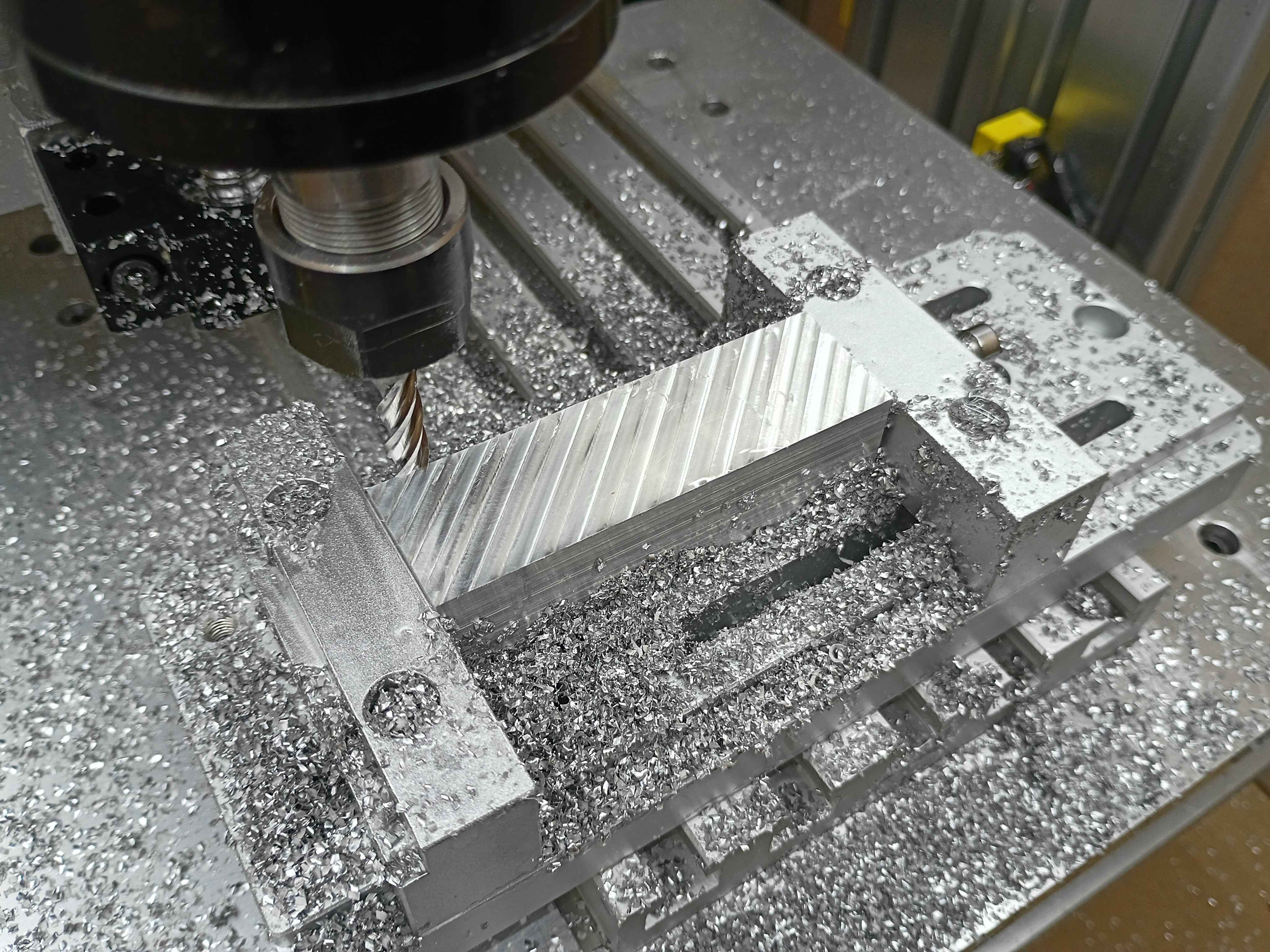
Added 60sec timed pump control button to the web UI. That's roughly half the bucket per pump. 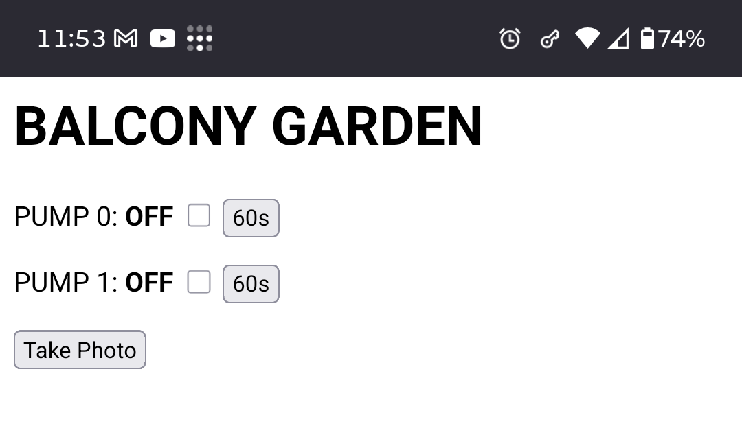
Learning more about the CAM workbench. 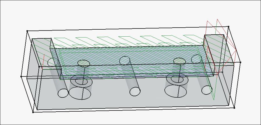
Working on the cnc toolpaths. 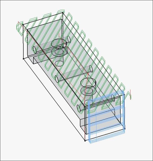
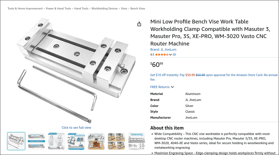
Modeled the 3 distinct parts of the low-profile vise. It's based on this product on Amazon. It has a bolt pattern than more closely matches the T-slot spacing on the 00001 CNC prototype, is sized for standard (cheaper) imperial material stock thicknesses, has more horizontal threaded holes for clamp-up, thru threaded holes for the side clamp pieces, and lower-profile clamp pieces that should provide adequate clearance for the entire y-axis of the 00001 CNC prototype to move without crashing into the vise. The 00003-003 large lower slotted piece can also potentially be made thinner to reduce cost and improve clearance. The 1x -001 and 2x-002 pieces will be machined on the 00001 CNC from aluminum to replace the stock ones on the product purchased from Amazon as a first preliminary test of cutting aluminum. Added the assembly to the repository. 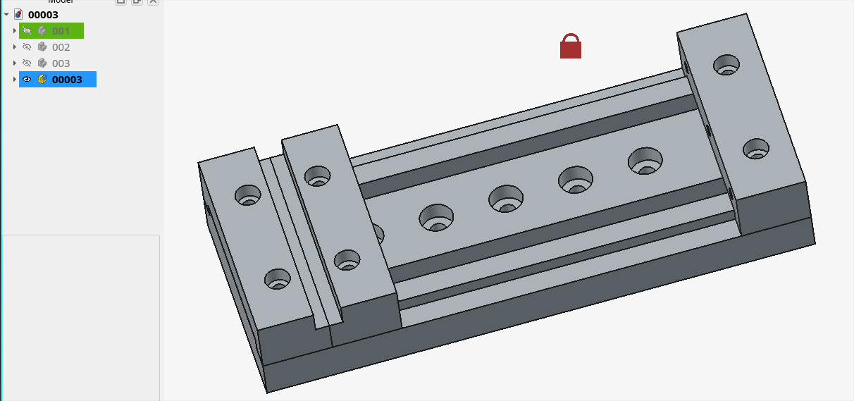
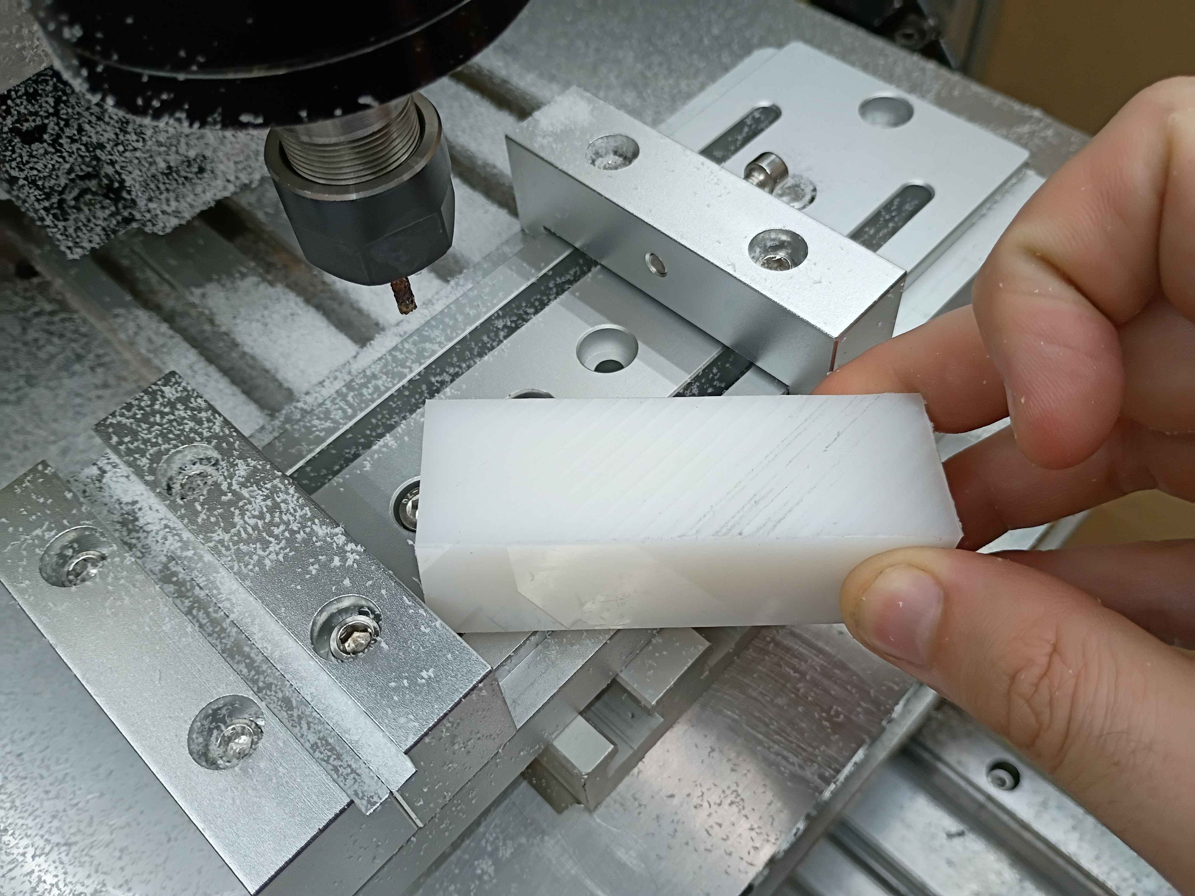
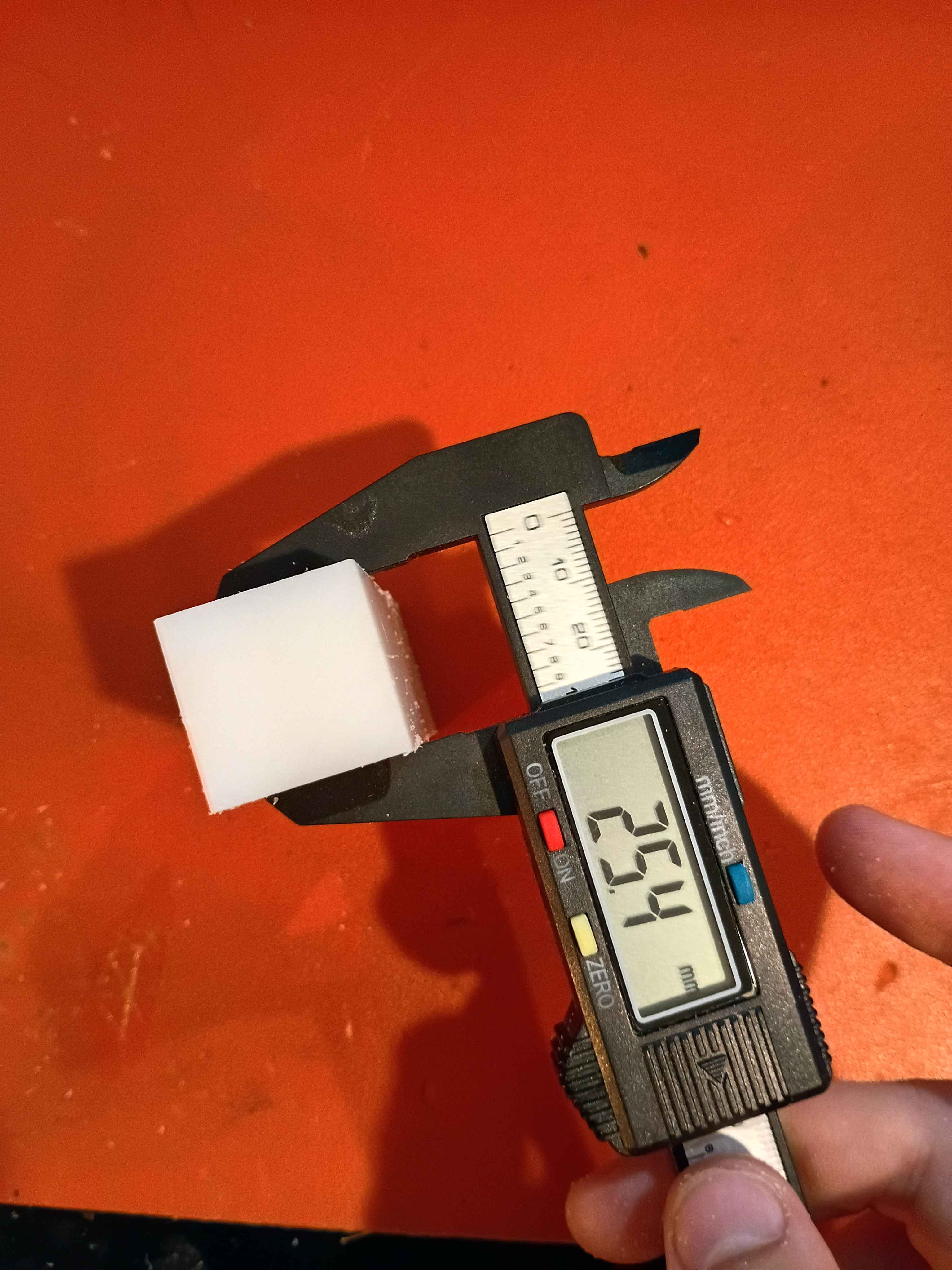
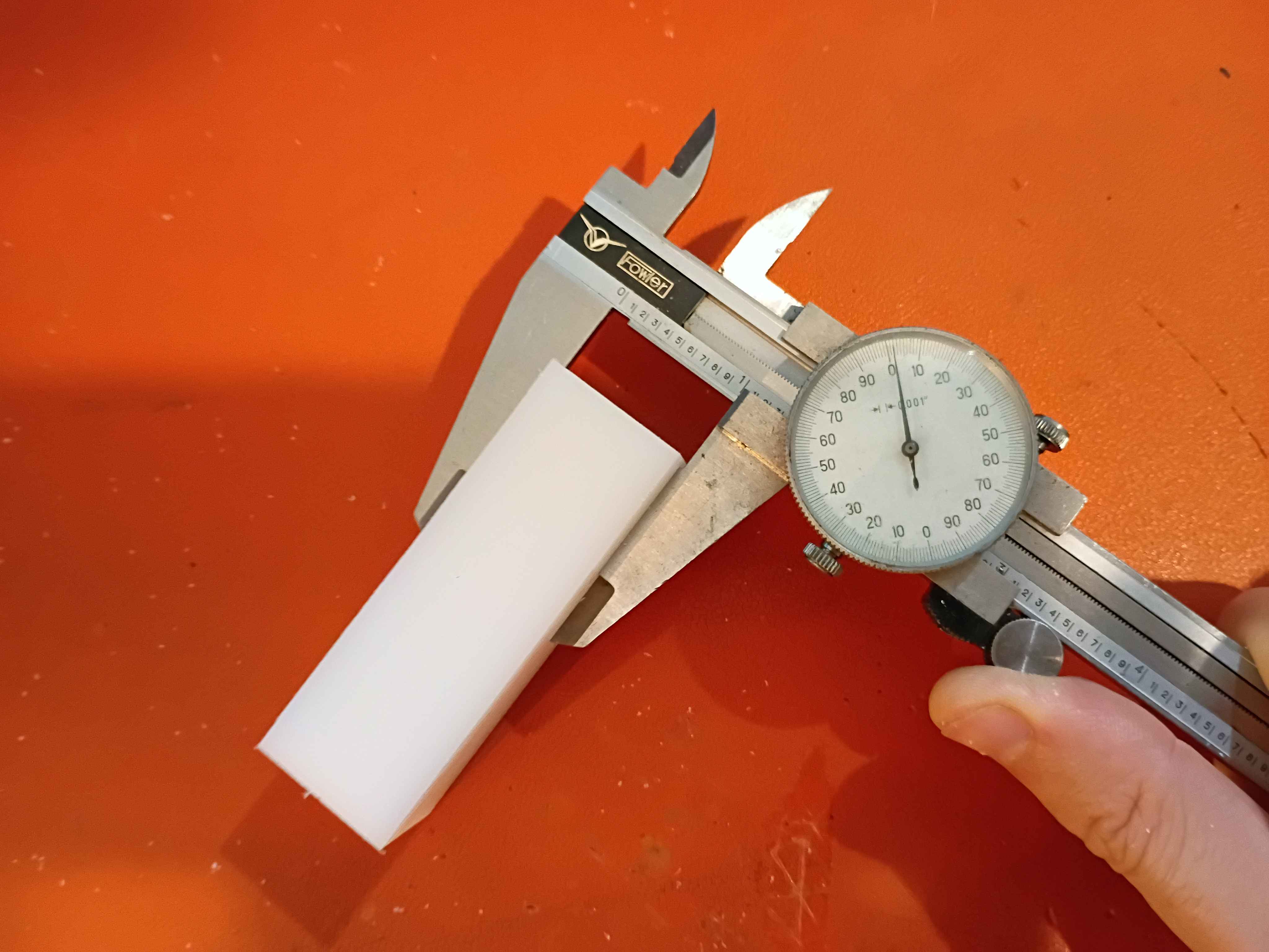
Realized that there is a fundamental flaw in the setup that completely disqualifies a large portion of the y-axis (long axis). There are a couple bandaid fix options for it, and the best are to just drop the vice onto the gantry plate, reduce the Z axis ballscrew length, or just avoid large swaths of the milling volume. Was able to face the top of a 1x1x3" piece of HDPE within .001 (although that's more a measure of how well I was able to guestimate Z-zero position of the top of the material. The total variation across the part was .000 to .002. It cut well but produced a lot of HDPE dust because I was using a PCB drill instead of an endmill for fear of breaking something more valuable on the first real milling attempt. I was cutting a 30 mm/min and 100 Hz with a 1/8" PCB drill, which corresponds to around 5000RPM. I learned a lot about how to use the MachCNC software. See video. 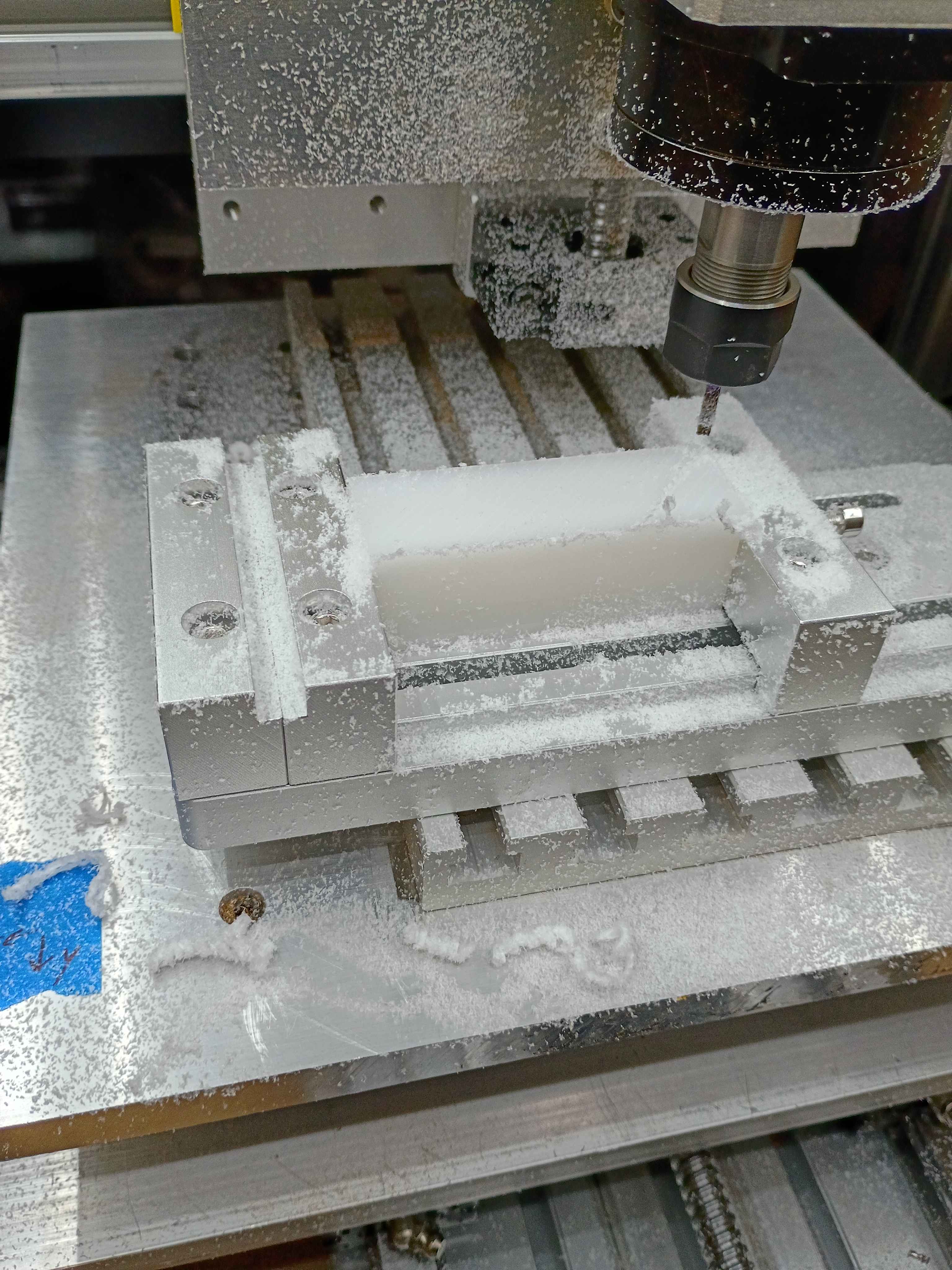
Added some functionality to the server to allow remote control of the pumps. 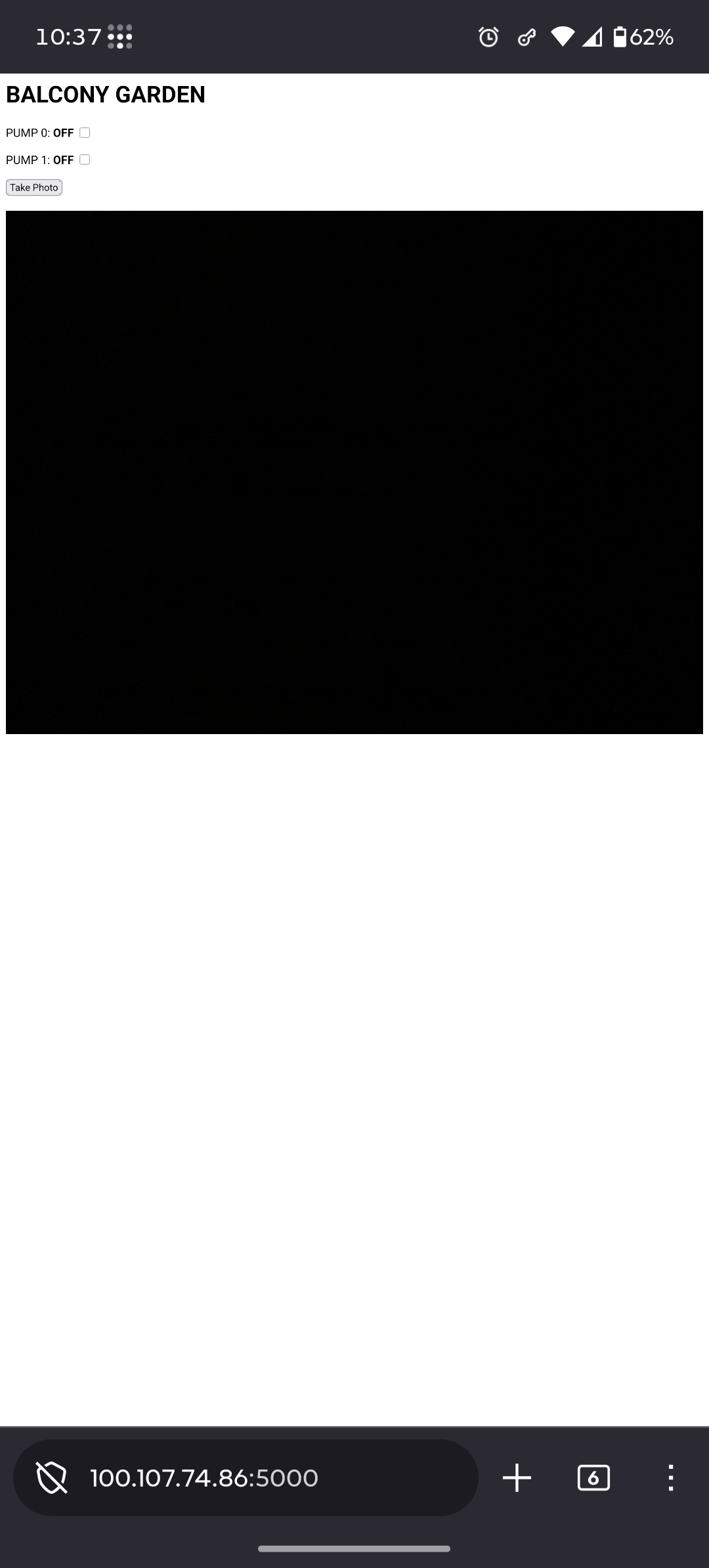
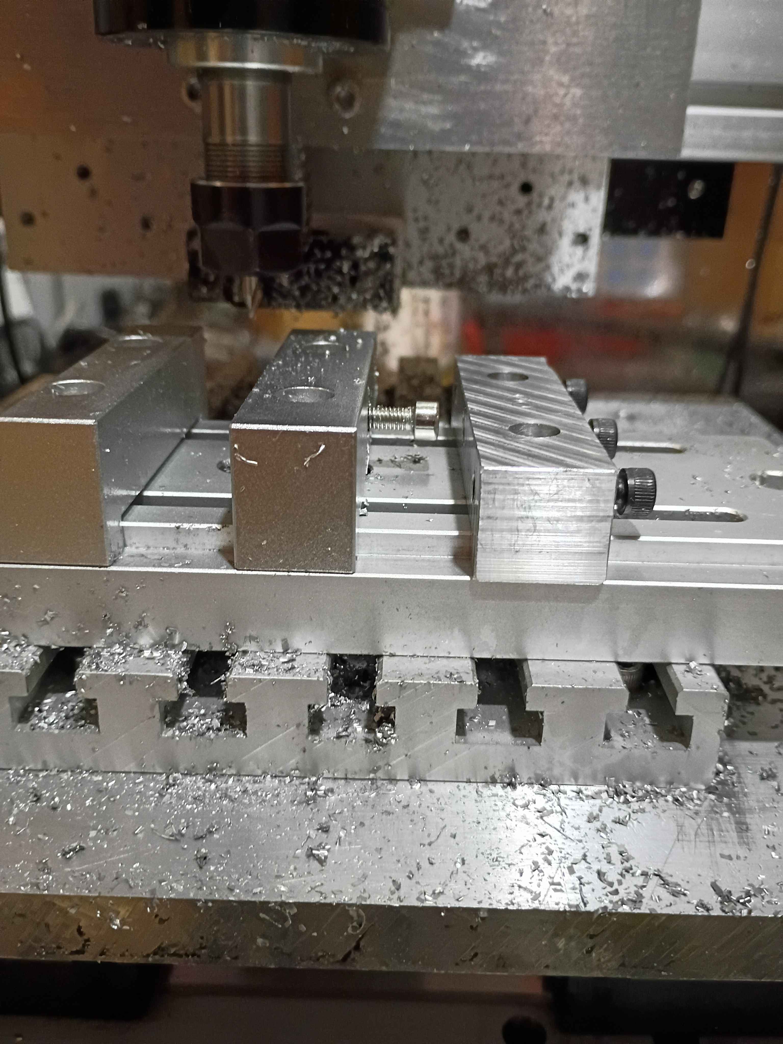
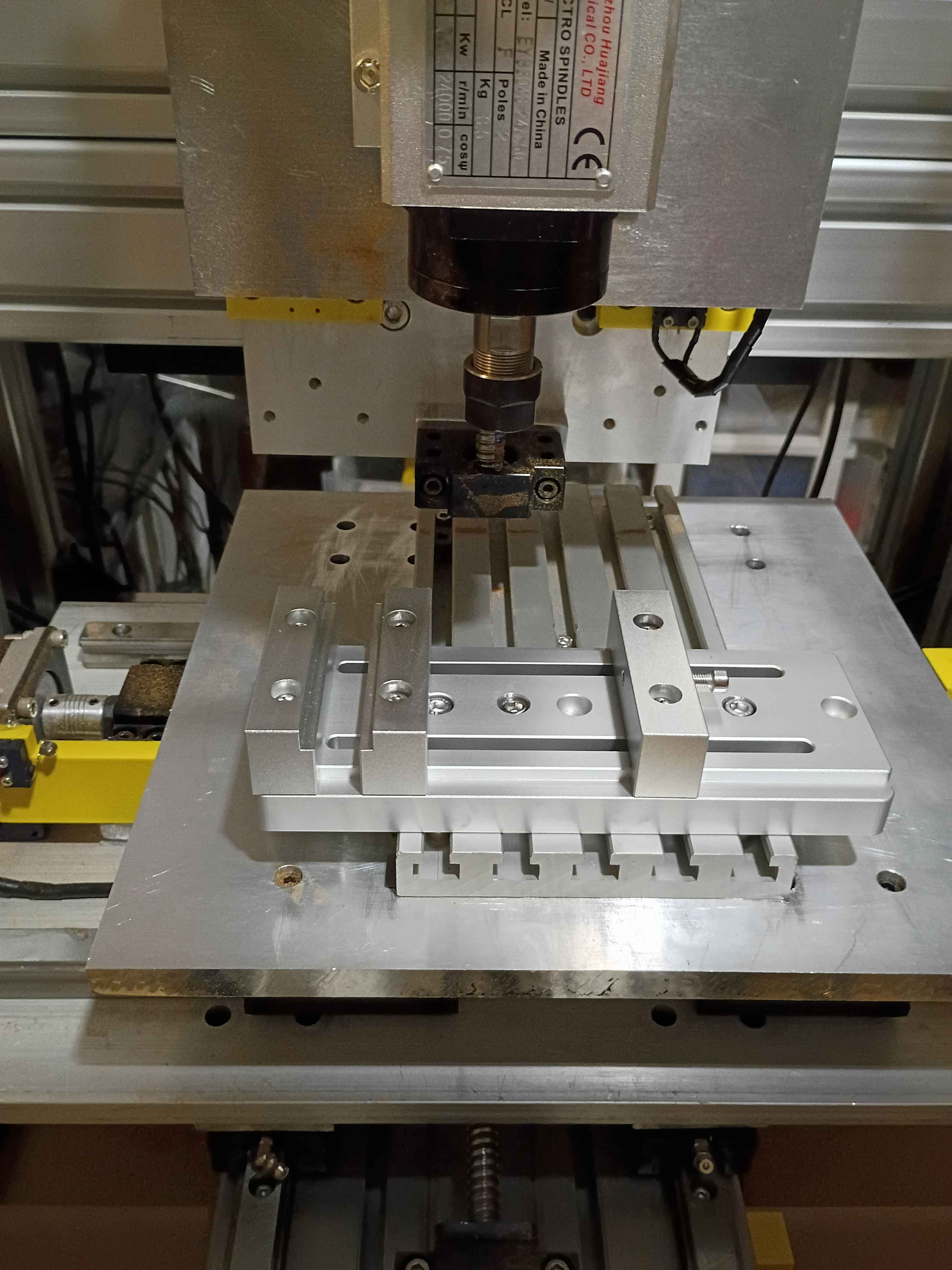
Received and mounted new 8A 12V power supply for the lights, which makes them way brighter, not overheat the power supply, not flicker out occasionally, and not dim the lights when turning on the fans. Also received the new machining vice and drilled (and counterbored) 3 new holes with a 1" spacing. Mounted up everything successfully, and ready for a test run tomorrow. The only caveat is that technically the vice is able to run into some of the z-axis components if the user is not careful, so that is a design flaw in the entire z axis setup. 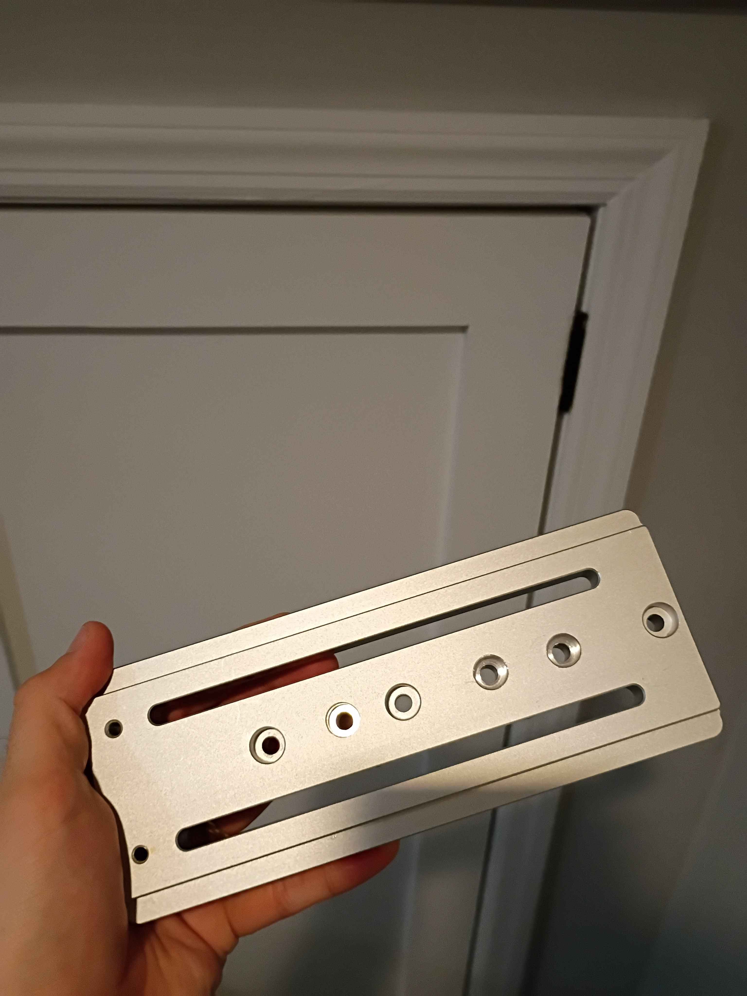
Wired up everything and successfully tested the 2 pump systems. It's not pretty, but it works. Also hooked up all the irrigation lines and staked them into the various pots in the dirt. Now only the software and container/camera mount remains. 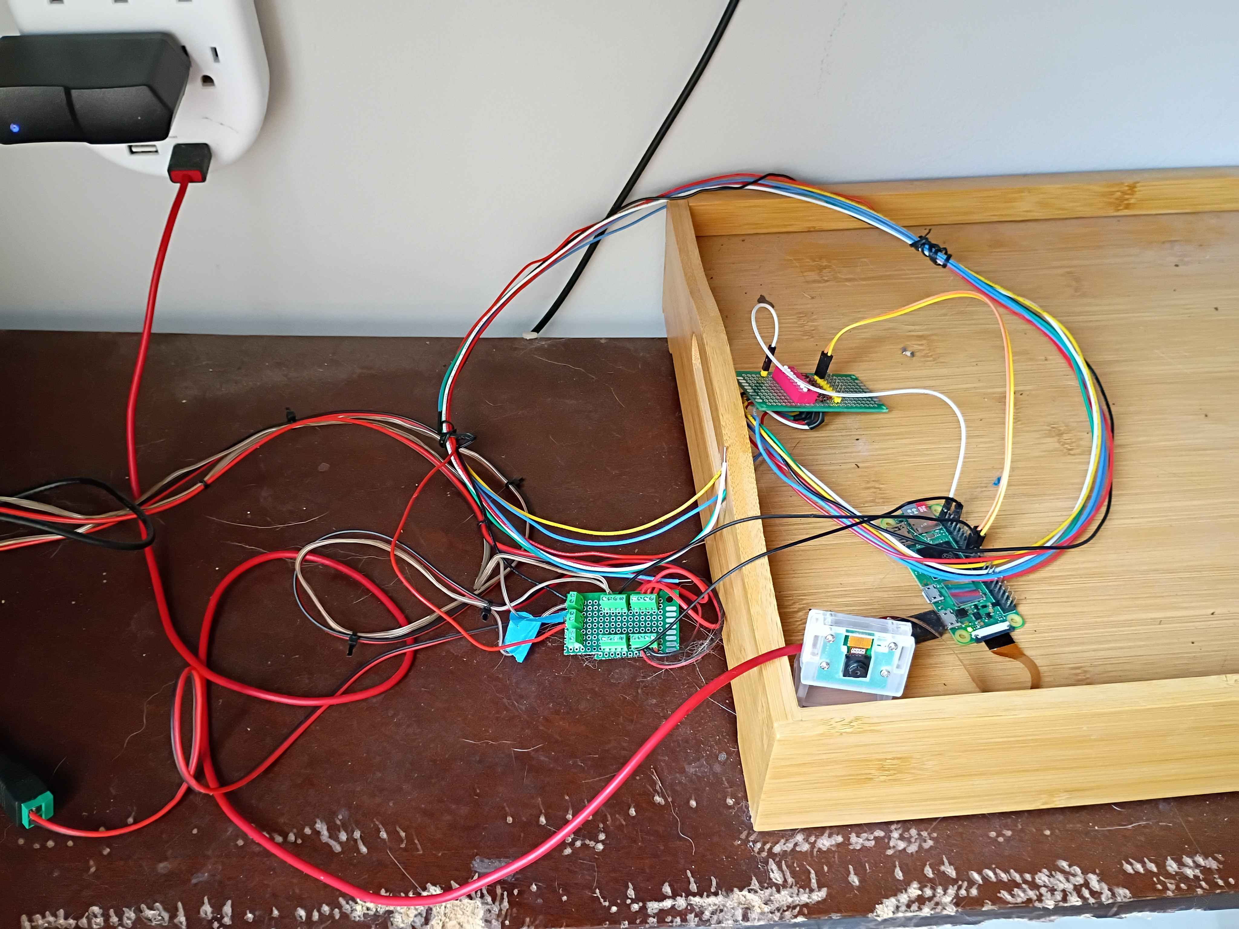
Rewired the control circuitry and pump lines, setting everything outside for a test run tomorrow. Using large coffee mugs to weigh down the pump inlet tubing. Soldered some screw terminals to a small breadboard to make removable connections between the Pi and the relays. 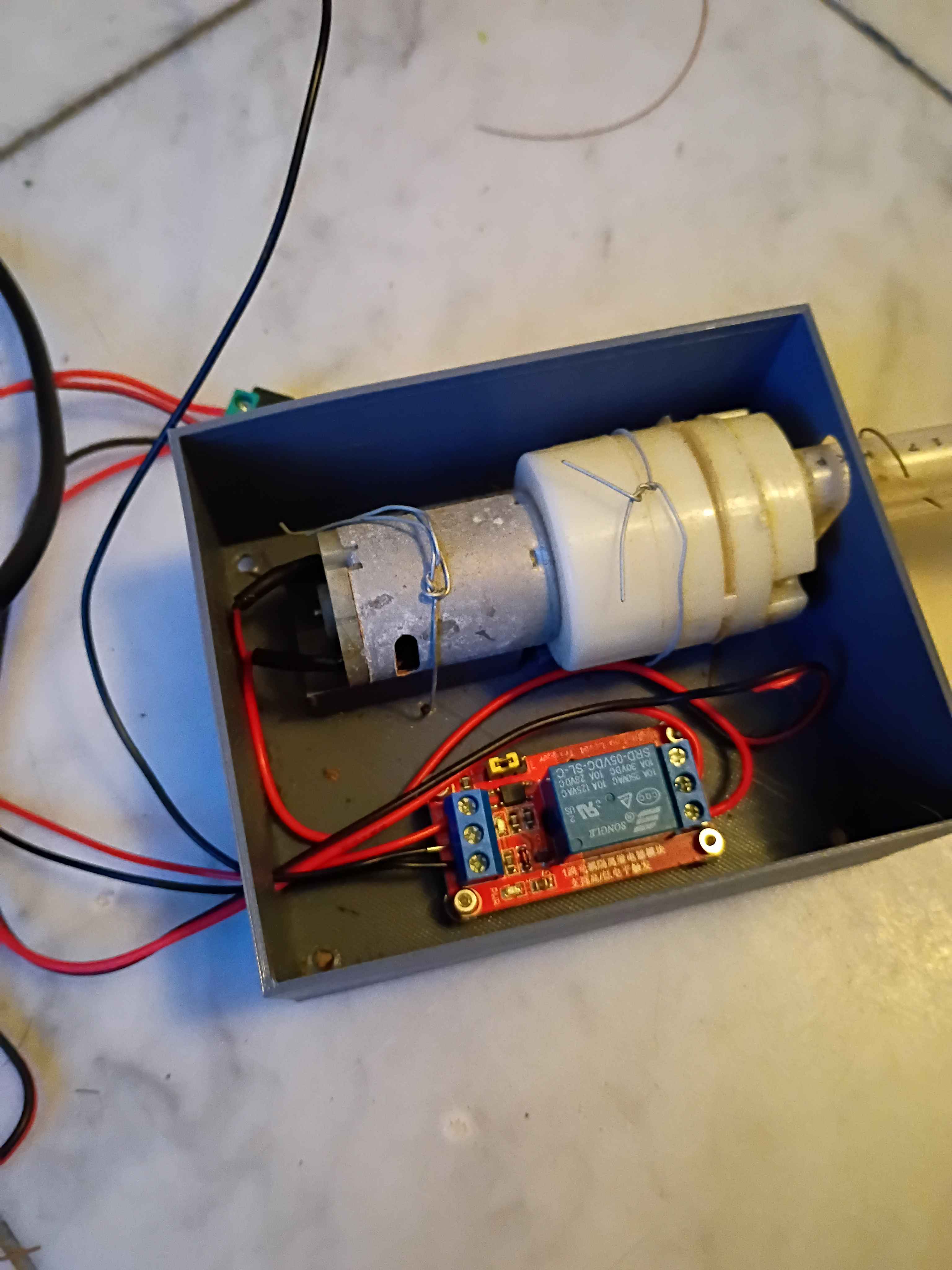
Determined Z-axis range of motion and purchased a clamp that allows for most of the use of the range, though it will require some extra mounting holes drilled into it. Also purchased some bellows to protect the ballscrews. 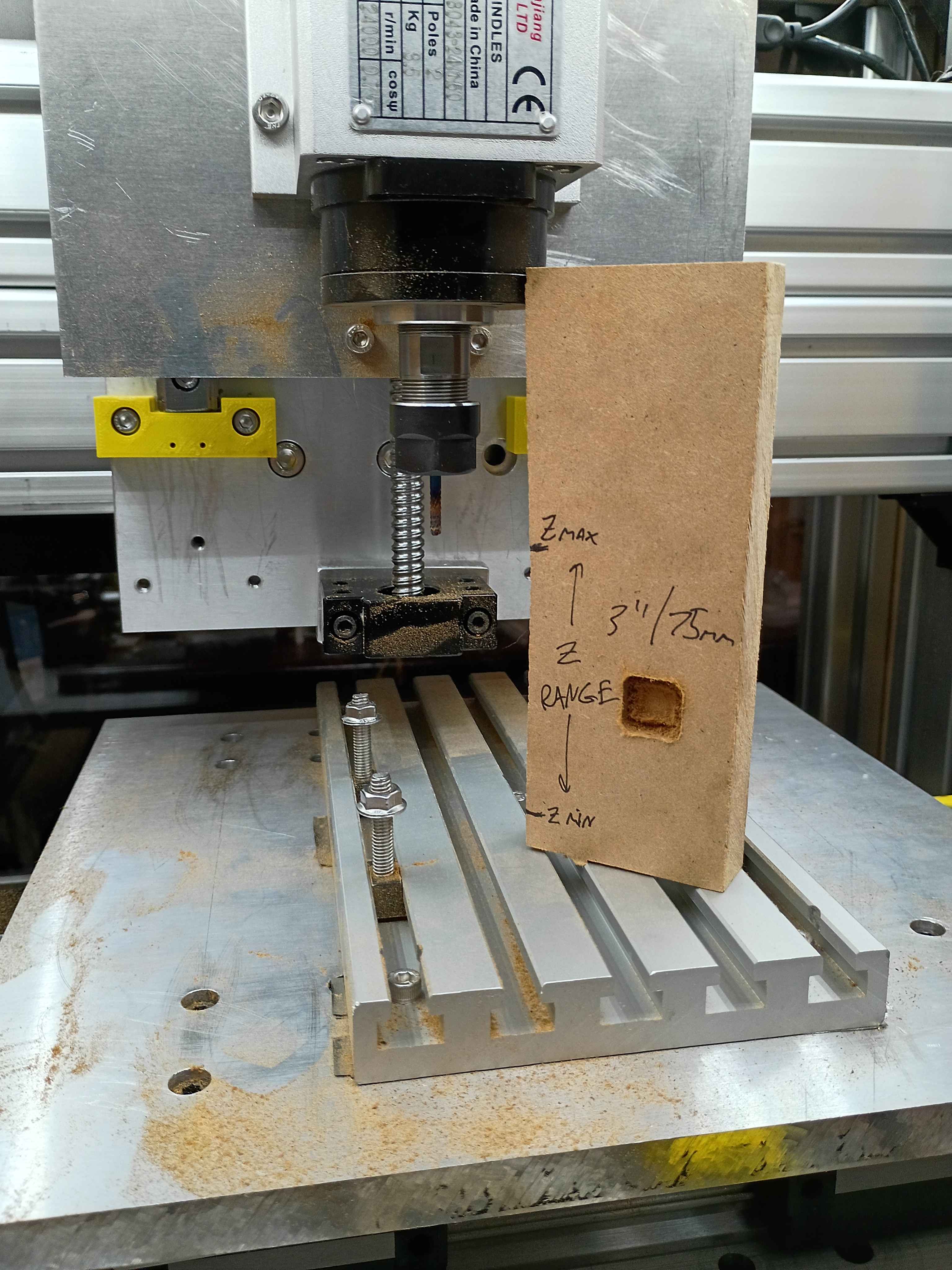
Conducted more tests on the CNC. Depth does seem to work properly, except that I run out of travel downwards in some situations. Can possibly be resolved with different fixturing setup. Also realized the 12V power supply I had on hand does not provide enough amps for 3 fans and the lighting in parallel. Ordered a more powerful replacement. 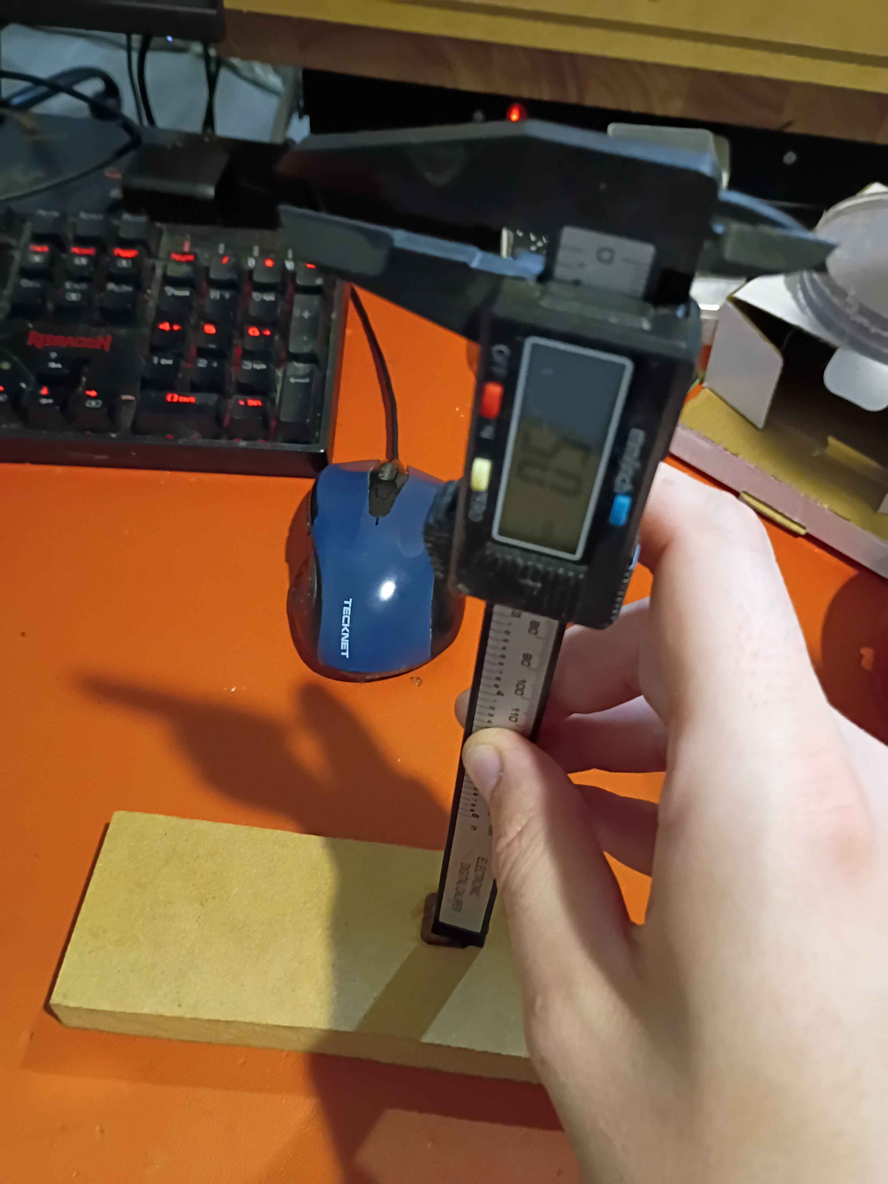
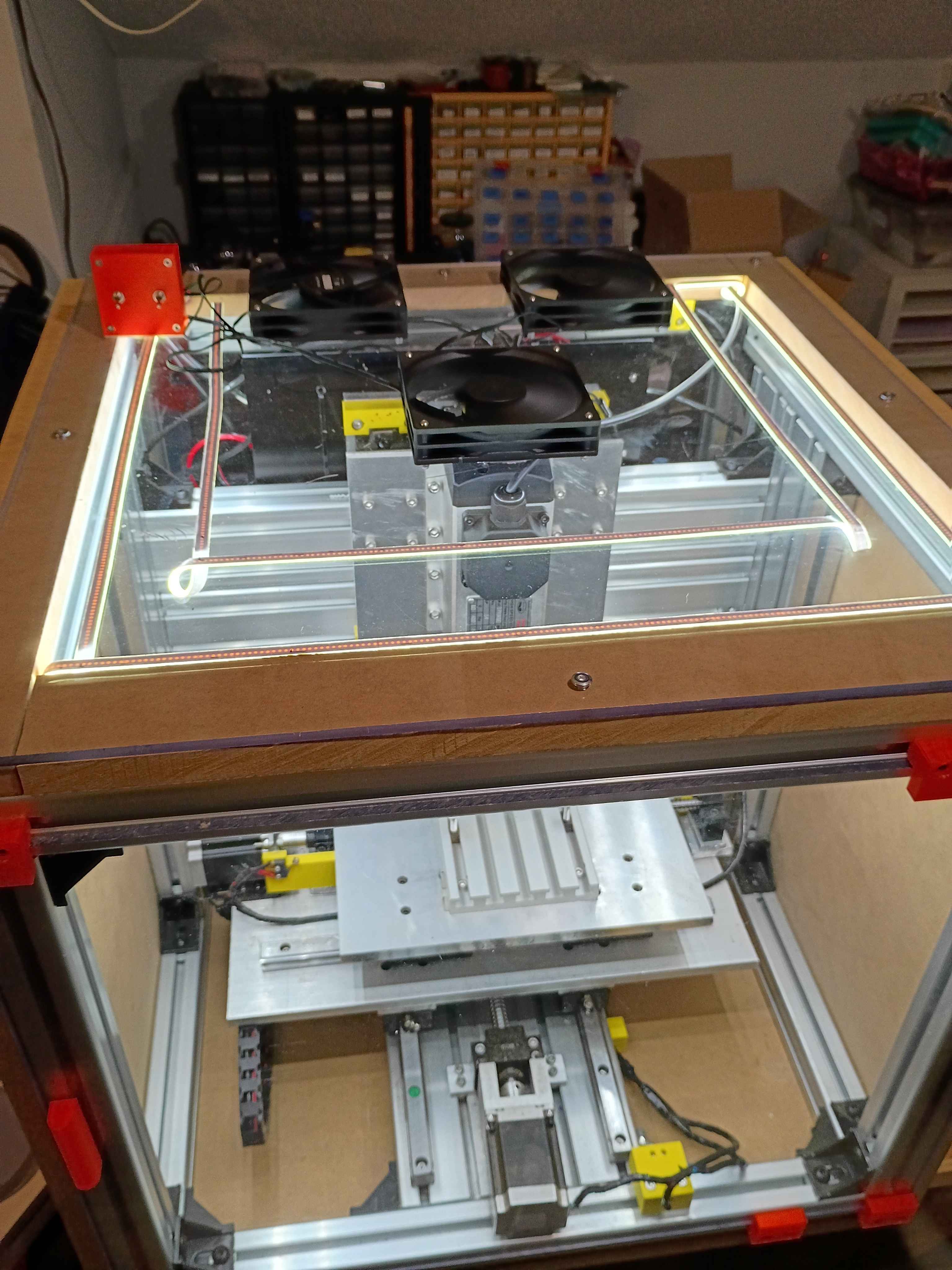
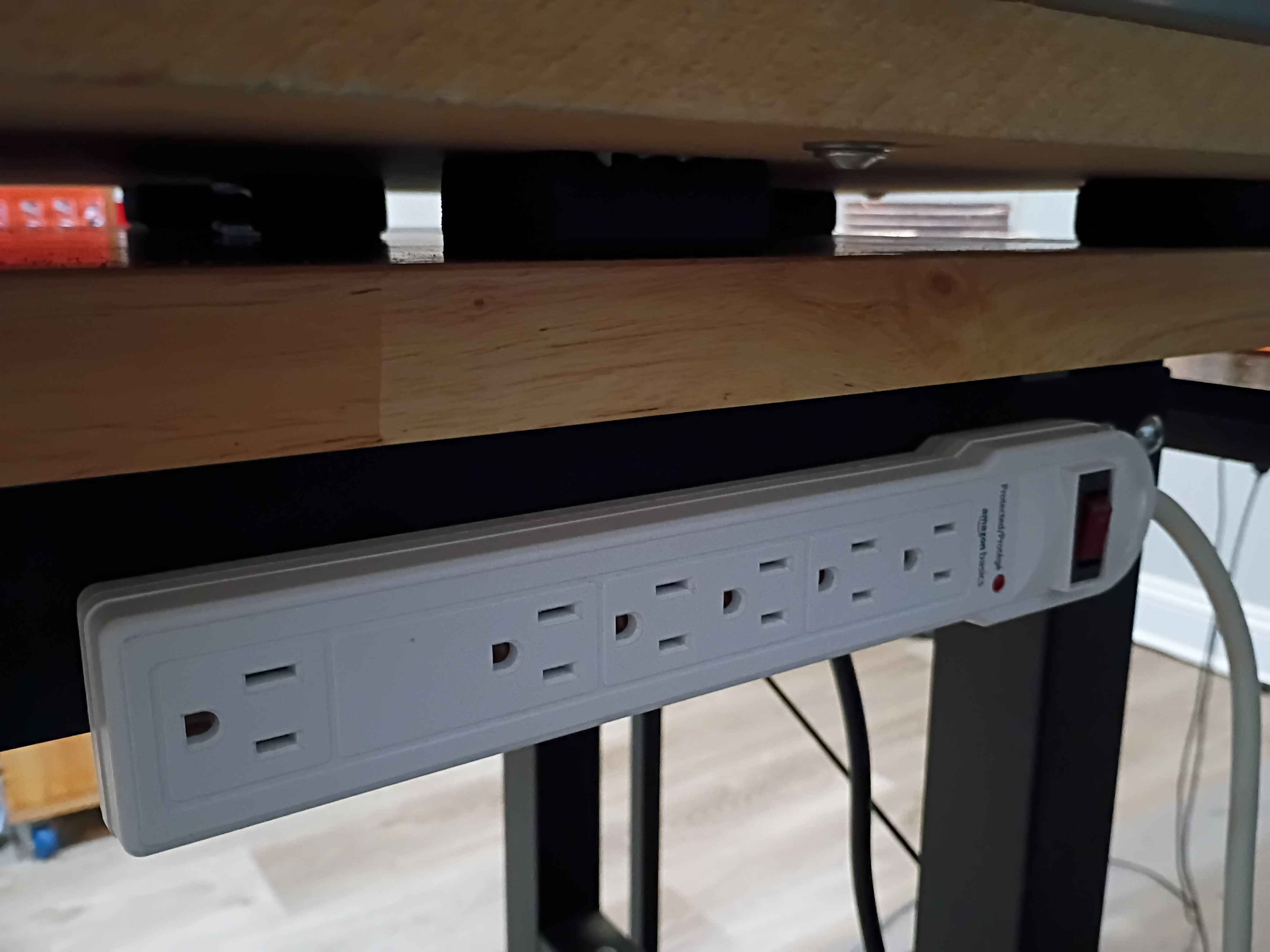
Affixed lights to the top panel, soldered their connection to the control box, and attached the entire top panel to the rest of the frame assembly. Drilled and bolted a power strip to the side of the workbench to power all the CNC subsystems, including the panel lights and ventilation. Did a test and was quite impressed with the lighting. There are no shadows. I wrapped the LED strips in loops at the right angles to avoid soldering, which worked well. 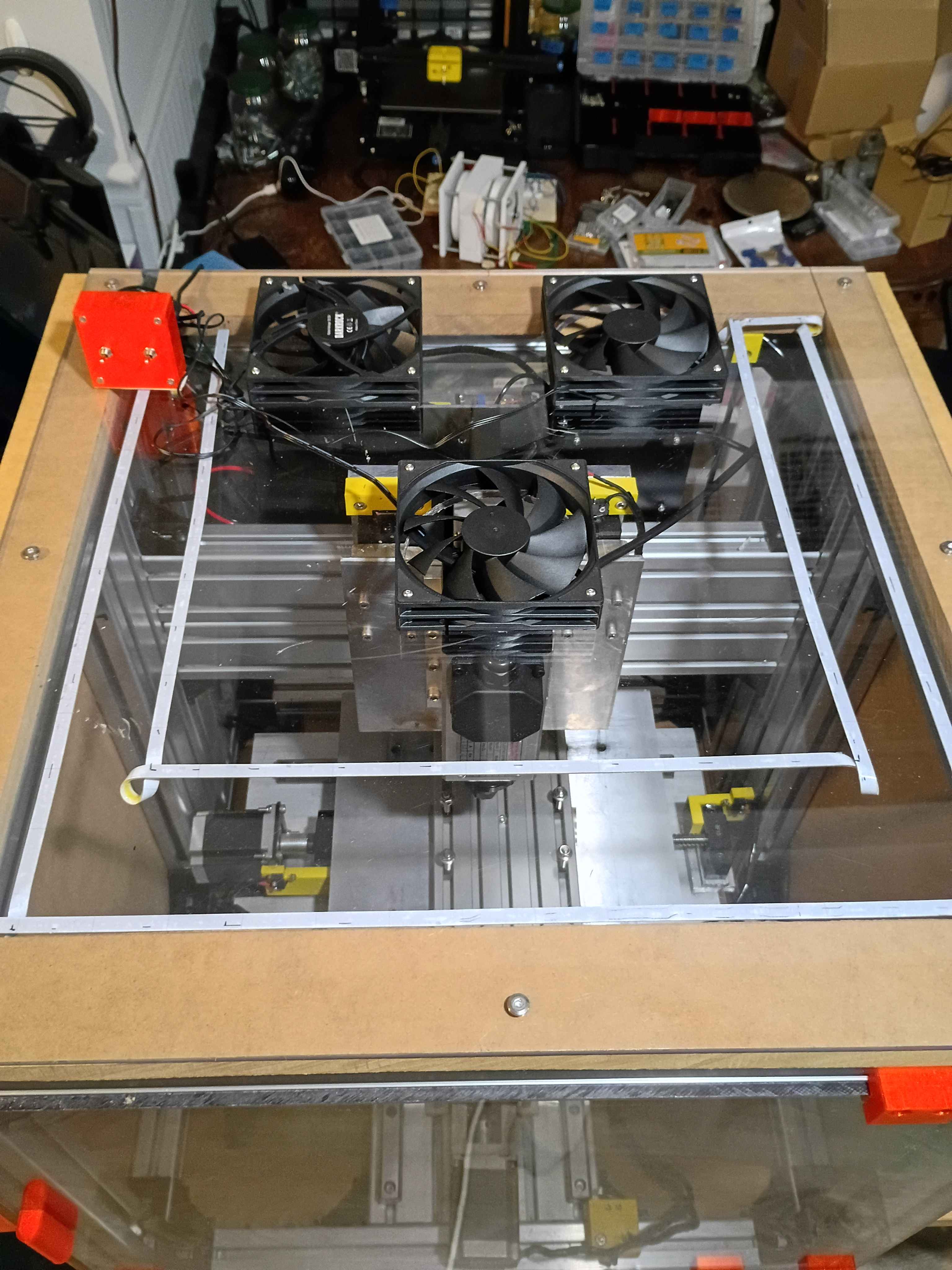
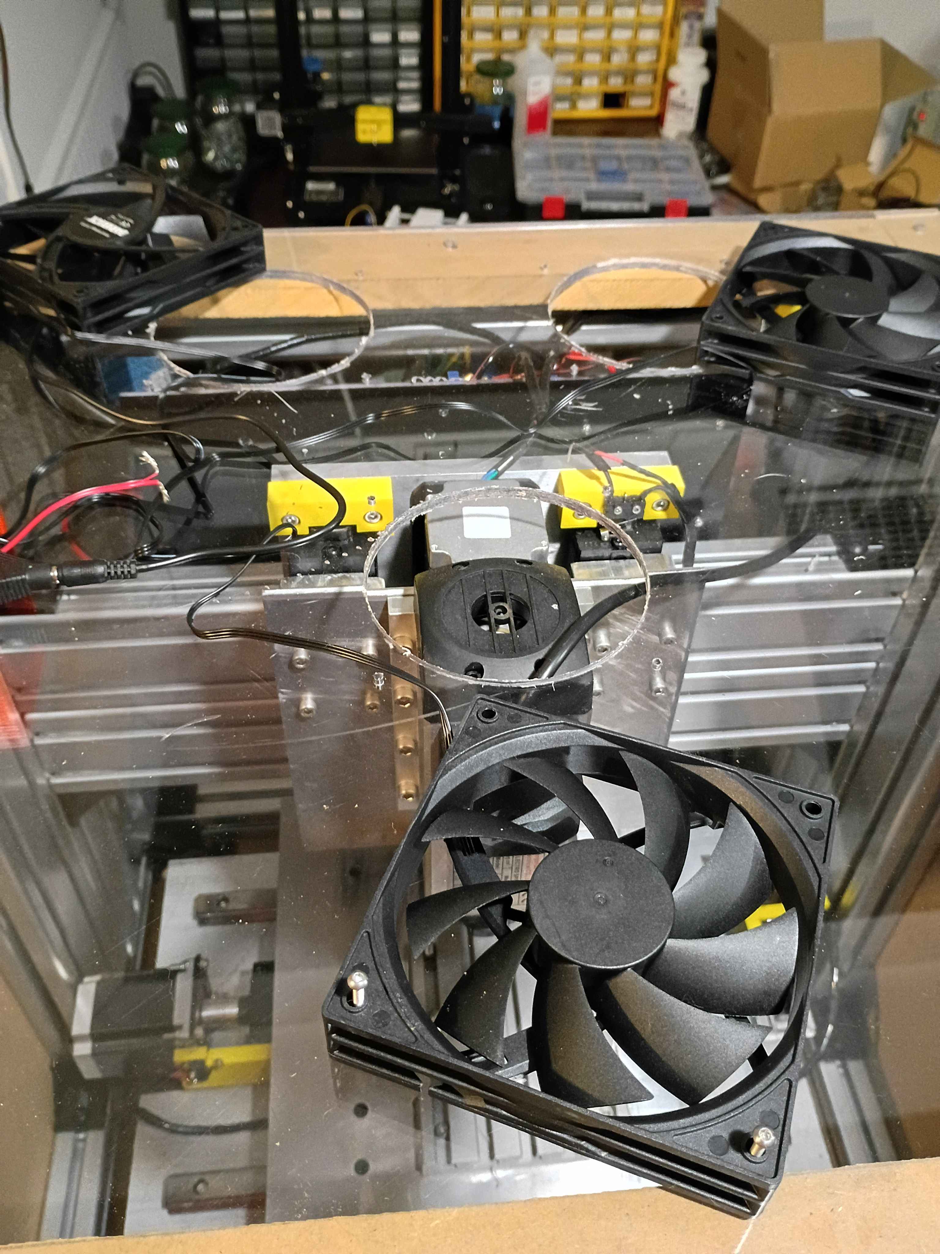
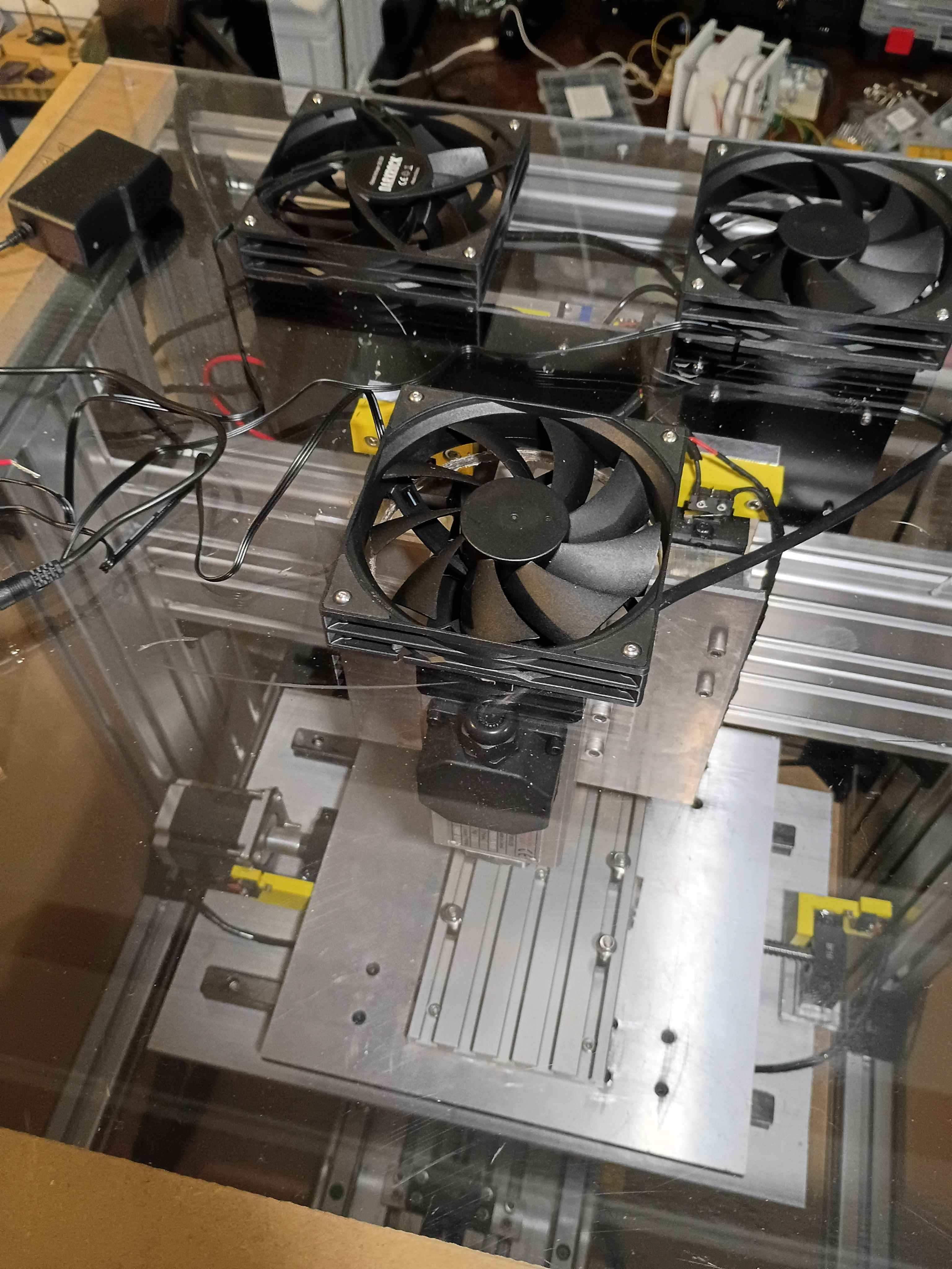
Cut 3x ventilation holes in top panel using hole saw (very hard, I blame the saw). Installed the 3x vent fans with ME screws and tested them.